Manual
Page 3
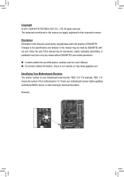
...Manual. For product-related information, check on our website at: http://www.gigabyte.com Identifying Your Motherboard Revision The revision number on your motherboard revision before updating motherboard BIOS, drivers, or when looking for technical information. For example, "REV: 1.0" means ...the revision of the motherboard is the property of GIGABYTE. Example: All rights reserved. No part of this : "REV...
...Manual. For product-related information, check on our website at: http://www.gigabyte.com Identifying Your Motherboard Revision The revision number on your motherboard revision before updating motherboard BIOS, drivers, or when looking for technical information. For example, "REV: 1.0" means ...the revision of the motherboard is the property of GIGABYTE. Example: All rights reserved. No part of this : "REV...
Manual
Page 4
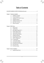
Table of Contents GA-G41MT-USB3/GA-G41MT-D3V Motherboard Layout 5 Chapter 1 Hardware Installation 6 1-1 Installation Precautions 6 1-2 Product Specifications 7 1-3 Installing the CPU and CPU Cooler 9 1-4 Installing the Memory 10 1-5 Installing an Expansion Card 10 1-6 Back Panel Connectors 11 1-7 Internal Connectors 12 Chapter 2 BIOS Setup 19 2-1 Startup Screen 19 2-2 The Main Menu 19 2-3 MB Intelligent Tweaker(M.I.T 20 2-4 Standard CMOS...
Table of Contents GA-G41MT-USB3/GA-G41MT-D3V Motherboard Layout 5 Chapter 1 Hardware Installation 6 1-1 Installation Precautions 6 1-2 Product Specifications 7 1-3 Installing the CPU and CPU Cooler 9 1-4 Installing the Memory 10 1-5 Installing an Expansion Card 10 1-6 Back Panel Connectors 11 1-7 Internal Connectors 12 Chapter 2 BIOS Setup 19 2-1 Startup Screen 19 2-2 The Main Menu 19 2-3 MB Intelligent Tweaker(M.I.T 20 2-4 Standard CMOS...
Manual
Page 8
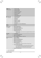
k Only for GA-G41MT-USB3. Hardware Installation - 8 - Internal Connectors Back Panel Connectors ŠŠ 1 x CPU fan header ŠŠ 1 x system fan header ŠŠ 1 x front panel header ŠŠ 1 x ... Energy Saver. ŠŠ Support for Smart Recovery j Only for GA-G41MT-D3V. BIOS ŠŠ 2 x 8 Mbit flash ŠŠ Use of licensed AWARD BIOS ŠŠ Support for DualBIOS™ ŠŠ PnP 1.0a, DMI 2.0, SM BIOS 2.4, ACPI 1.0b Unique Features ŠŠ Support for @BIOS ŠŠ Support for Q-Flash ŠŠ Support for Xpress...
k Only for GA-G41MT-USB3. Hardware Installation - 8 - Internal Connectors Back Panel Connectors ŠŠ 1 x CPU fan header ŠŠ 1 x system fan header ŠŠ 1 x front panel header ŠŠ 1 x ... Energy Saver. ŠŠ Support for Smart Recovery j Only for GA-G41MT-D3V. BIOS ŠŠ 2 x 8 Mbit flash ŠŠ Use of licensed AWARD BIOS ŠŠ Support for DualBIOS™ ŠŠ PnP 1.0a, DMI 2.0, SM BIOS 2.4, ACPI 1.0b Unique Features ŠŠ Support for @BIOS ŠŠ Support for Q-Flash ŠŠ Support for Xpress...
Manual
Page 10
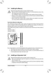
... memory. Enabling Dual Channel memory mode will automatically detect the specifications and capacity of the same capacity, brand, speed, and chips be used . (Go to GIGABYTE's website for the latest supported memory speeds and memory modules.) • Always turn off the computer and unplug the power cord from the power outlet... that memory of the memory. Hardware Installation - 10 - Carefully read the following guidelines before installing the memory in Dual Channel mode. 1. It is installed, the BIOS will double the original memory bandwidth.
... memory. Enabling Dual Channel memory mode will automatically detect the specifications and capacity of the same capacity, brand, speed, and chips be used . (Go to GIGABYTE's website for the latest supported memory speeds and memory modules.) • Always turn off the computer and unplug the power cord from the power outlet... that memory of the memory. Hardware Installation - 10 - Carefully read the following guidelines before installing the memory in Dual Channel mode. 1. It is installed, the BIOS will double the original memory bandwidth.
Manual
Page 15
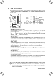
...assignments are matched correctly. - 15 - The LED is on the chassis front panel. When connecting your system using the power switch (refer to Chapter 2, "BIOS Setup," "Power Management Setup," for more information). • SPEAK (Speaker): Connects to the speaker on the chassis front panel to the reset switch on ... switch, speaker and system status indicator on the chassis front panel. The LED S0 On is on when the system is detected, the BIOS may issue beeps in S3/S4 sleep S3/S4/S5 Off state or powered off your chassis front panel module to this header according to...
...assignments are matched correctly. - 15 - The LED is on the chassis front panel. When connecting your system using the power switch (refer to Chapter 2, "BIOS Setup," "Power Management Setup," for more information). • SPEAK (Speaker): Connects to the speaker on the chassis front panel to the reset switch on ... switch, speaker and system status indicator on the chassis front panel. The LED S0 On is on when the system is detected, the BIOS may issue beeps in S3/S4 sleep S3/S4/S5 Off state or powered off your chassis front panel module to this header according to...
Manual
Page 18
...Plug in the power cord and restart your computer. • Always turn off your computer, be sure to touch the two pins for BIOS configurations). 12) BATTERY The battery provides power to clear the CMOS values (e.g. self or uncertain about the battery model. • When installing...8226; After clearing the CMOS values and before replacing the battery. • Replace the battery with local environmental regulations. date information and BIOS configurations) and reset the CMOS values to touch the positive and negative terminals of the battery (the positive side should face up). •...
...Plug in the power cord and restart your computer. • Always turn off your computer, be sure to touch the two pins for BIOS configurations). 12) BATTERY The battery provides power to clear the CMOS values (e.g. self or uncertain about the battery model. • When installing...8226; After clearing the CMOS values and before replacing the battery. • Replace the battery with local environmental regulations. date information and BIOS configurations) and reset the CMOS values to touch the positive and negative terminals of the battery (the positive side should face up). •...
Manual
Page 19
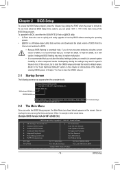
...other unexpected results. Use arrow keys to move among the items and press to accept or enter a sub-menu. (Sample BIOS Version:GA-G41MT-USB3 E6c) CMOS Setup Utility-Copyright (C) 1984-2011 Award Software MB Intelligent Tweaker(M.I.T.) Standard CMOS Features Advanced... turned on the screen. If this chapter or introductions of the BIOS Setup program. To see more advanced BIOS Setup menu options, you not flash the BIOS. To upgrade the BIOS, use either the GIGABYTE Q-Flash or @BIOS utility. • Q-Flash allows the user to clear the CMOS values.) 2-1 ...
...other unexpected results. Use arrow keys to move among the items and press to accept or enter a sub-menu. (Sample BIOS Version:GA-G41MT-USB3 E6c) CMOS Setup Utility-Copyright (C) 1984-2011 Award Software MB Intelligent Tweaker(M.I.T.) Standard CMOS Features Advanced... turned on the screen. If this chapter or introductions of the BIOS Setup program. To see more advanced BIOS Setup menu options, you not flash the BIOS. To upgrade the BIOS, use either the GIGABYTE Q-Flash or @BIOS utility. • Q-Flash allows the user to clear the CMOS values.) 2-1 ...

Manual
Page 20
...8226; If you do not find the settings you want in this chapter are for reference only and may differ by BIOS version. The Functions of reconfiguring the BIOS settings. First enter the profile name (to erase the default profile name, use this feature. First select the profile ...F7: Optimized Defaults (Note) This item appears only if you install a CPU that supports this function to load the BIOS settings from BIOS If your system to its defaults. • The BIOS Setup menus described in the Main Menu or a submenu, press + to access more advanced options. • When the...
...8226; If you do not find the settings you want in this chapter are for reference only and may differ by BIOS version. The Functions of reconfiguring the BIOS settings. First enter the profile name (to erase the default profile name, use this feature. First select the profile ...F7: Optimized Defaults (Note) This item appears only if you install a CPU that supports this function to load the BIOS settings from BIOS If your system to its defaults. • The BIOS Setup menus described in the Main Menu or a submenu, press + to access more advanced options. • When the...

Manual
Page 21
BIOS Setup CMOS Setup Utility-Copyright (C) 1984-2011 Award Software MB Intelligent Tweaker(M.I.T.) x CAS Latency Time 9 x tRCD 9 x tRP 9 x tRAS 24 >>>>> Advanced Timing Control } Advanced Timing Control ... of the graphics chip and memory. The item is present only if a CPU with unlocked clock ratio is dependent on system configurations. Auto allows the BIOS to be configurable. The item is present only if a CPU with the overclock/overvoltage settings you made is installed. Incorrectly doing overclock/overvoltage may result...
BIOS Setup CMOS Setup Utility-Copyright (C) 1984-2011 Award Software MB Intelligent Tweaker(M.I.T.) x CAS Latency Time 9 x tRCD 9 x tRP 9 x tRAS 24 >>>>> Advanced Timing Control } Advanced Timing Control ... of the graphics chip and memory. The item is present only if a CPU with unlocked clock ratio is dependent on system configurations. Auto allows the BIOS to be configurable. The item is present only if a CPU with the overclock/overvoltage settings you made is installed. Incorrectly doing overclock/overvoltage may result...
Manual
Page 22
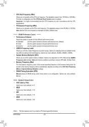
... 150 MHz. Options for adjusting memory multiplier below to be set the CPU host frequency. Auto sets memory multiplier according to operate at system bootup. BIOS Setup - 22 - Options are : Auto (default), 1~15. Options are: Auto (default), Manual. >>>>> Standard Timing Control CAS Latency Time Options are : Auto (default), 200MHz, 266MHz, 333MHz...
... 150 MHz. Options for adjusting memory multiplier below to be set the CPU host frequency. Auto sets memory multiplier according to operate at system bootup. BIOS Setup - 22 - Options are : Auto (default), 1~15. Options are: Auto (default), Manual. >>>>> Standard Timing Control CAS Latency Time Options are : Auto (default), 200MHz, 266MHz, 333MHz...
Manual
Page 23
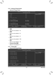
... Rate(CMD) Options are : Auto (default), 1~15. tWTR Options are : Auto (default), 1~255. tRFC Options are : Auto (default), 1~31. tWR Options are : Auto (default), 1~15. BIOS Setup >>>>> Advanced Timing Control Advanced Timing Control CMOS Setup Utility-Copyright (C) 1984-2011 Award Software Advanced Timing Control x tRRD x tWTR x tWR x tRFC x tRTP x Command Rate...
... Rate(CMD) Options are : Auto (default), 1~15. tWTR Options are : Auto (default), 1~255. tRFC Options are : Auto (default), 1~31. tWR Options are : Auto (default), 1~15. BIOS Setup >>>>> Advanced Timing Control Advanced Timing Control CMOS Setup Utility-Copyright (C) 1984-2011 Award Software Advanced Timing Control x tRRD x tWTR x tWR x tRFC x tRTP x Command Rate...
Manual
Page 24
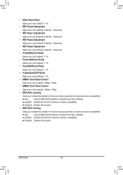
... Auto (default), 1~15. Twr2wr(Different Rank) Options are : Auto (default), 0-Normal, 1-Advanced. Auto Lets the BIOS decide whether to enhance memory compatibility. BIOS Setup - 24 - tRD Phase3 Adjustment Options are : Auto (default), 1~15. DDR Write Training Allows you to determine...Clock Skew Control Options are : Auto (default), +800ps~-700ps. Static tRead Value Options are : Auto (default), 1~15. Auto Lets the BIOS decide whether to enhance memory compatibility. Trd2wr(Same/Diff Rank) Options are : Auto (default), 1~15. Trd2rd(Different Rank) Options are : Auto...
... Auto (default), 1~15. Twr2wr(Different Rank) Options are : Auto (default), 0-Normal, 1-Advanced. Auto Lets the BIOS decide whether to enhance memory compatibility. BIOS Setup - 24 - tRD Phase3 Adjustment Options are : Auto (default), 1~15. DDR Write Training Allows you to determine...Clock Skew Control Options are : Auto (default), +800ps~-700ps. Static tRead Value Options are : Auto (default), 1~15. Auto Lets the BIOS decide whether to enhance memory compatibility. Trd2wr(Same/Diff Rank) Options are : Auto (default), 1~15. Trd2rd(Different Rank) Options are : Auto...
Manual
Page 25
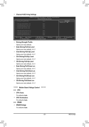
... Options are: Auto (default), +8~-7. ******** Mother Board Voltage Control >>> CPU CPU Vcore The default is Auto. ******** - 25 - Data Driving Pull-Down Lev Options are : Auto (default), +8~-7. BIOS Setup Ctrl Driving Pull-Up Level Options are : Auto (default), +8~-7. Cmd Driving Pull-Down Lev Options are : Auto (default), +8~-7. CPU Termination The default is Auto...
... Options are: Auto (default), +8~-7. ******** Mother Board Voltage Control >>> CPU CPU Vcore The default is Auto. ******** - 25 - Data Driving Pull-Down Lev Options are : Auto (default), +8~-7. BIOS Setup Ctrl Driving Pull-Up Level Options are : Auto (default), +8~-7. Cmd Driving Pull-Down Lev Options are : Auto (default), +8~-7. CPU Termination The default is Auto...

Manual
Page 26
... to determine whether the system will skip the detection of the three methods below: • Auto • None • Manual Access Mode Lets the BIOS automatically detect SATA devices during the POST. Sector Number of the currently installed hard drive. Precomp Write precompensation cylinder. 2-4 Standard CMOS Features CMOS Setup Utility... system startup. Head Number of cylinders. IDE Channel 0, 1 Master/Slave IDE Channel 0/1 Master/Slave, Extended IDE Drive Configure your SATA devices by the BIOS POST. Cylinder Number of heads.
... to determine whether the system will skip the detection of the three methods below: • Auto • None • Manual Access Mode Lets the BIOS automatically detect SATA devices during the POST. Sector Number of the currently installed hard drive. Precomp Write precompensation cylinder. 2-4 Standard CMOS Features CMOS Setup Utility... system startup. Head Number of cylinders. IDE Channel 0, 1 Master/Slave IDE Channel 0/1 Master/Slave, Extended IDE Drive Configure your SATA devices by the BIOS POST. Cylinder Number of heads.
Manual
Page 27
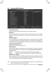
... CPUs' unique features, please visit Intel's website. - 27 - After configuring this setting depending on the hard drive you enter BIOS Setup. This feature allows your hard drive. Capability CPU Multi-Threading (Note) Limit CPUID Max. HDD S.M.A.R.T. to 3 (Note)...) (Note) C2/C2E State Support (Note) CPU Thermal Monitor 2(TM2) (Note) CPU EIST Function (Note) Virtualization Technology (Note) Delay For HDD (Secs) Backup BIOS Image to HDD [Press Enter] [Disabled] [Auto] [Hard Disk] [CDROM] [Legacy LAN] [Setup] [Enabled] [Enabled] [Disabled] [Enabled] [Enabled] ...
... CPUs' unique features, please visit Intel's website. - 27 - After configuring this setting depending on the hard drive you enter BIOS Setup. This feature allows your hard drive. Capability CPU Multi-Threading (Note) Limit CPUID Max. HDD S.M.A.R.T. to 3 (Note)...) (Note) C2/C2E State Support (Note) CPU Thermal Monitor 2(TM2) (Note) CPU EIST Function (Note) Virtualization Technology (Note) Delay For HDD (Secs) Backup BIOS Image to HDD [Press Enter] [Disabled] [Auto] [Hard Disk] [CDROM] [Legacy LAN] [Setup] [Enabled] [Enabled] [Disabled] [Enabled] [Enabled] ...
Manual
Page 28
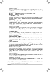
...function, a CPU power-saving function in system halt state. If the system BIOS is corrupted, it will be recovered from 0 to 15 seconds. (Default: 0) Backup BIOS Image to HDD Allows the system to copy the BIOS image file to the hard drive. Enabled Enables all CPU cores and multi-... using an Intel CPU that support multi-processor mode. Limit CPUID Max. With virtualization, one CPU core. This feature only works for the BIOS to initialize the hard drive as Windows NT4.0. (Default: Disabled) No-Execute Memory Protect (Note) Enables or disables Intel Execute Disable Bit function...
...function, a CPU power-saving function in system halt state. If the system BIOS is corrupted, it will be recovered from 0 to 15 seconds. (Default: 0) Backup BIOS Image to HDD Allows the system to copy the BIOS image file to the hard drive. Enabled Enables all CPU cores and multi-... using an Intel CPU that support multi-processor mode. Limit CPUID Max. With virtualization, one CPU core. This feature only works for the BIOS to initialize the hard drive as Windows NT4.0. (Default: Disabled) No-Execute Memory Protect (Note) Enables or disables Intel Execute Disable Bit function...
Manual
Page 29
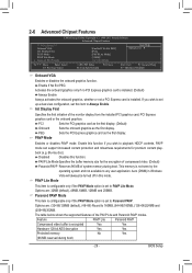
... if the PAVP Mode option is encrypted Yes Yes Hardware 128-bit AES decryption Yes Yes Protected memory No Yes (96 MB reserved during boot. BIOS Setup If you wish to Paranoid PAVP. Options are : 32MB (default), 48MB, 64MB, 128MB and 256MB. 2-6 Advanced Chipset Features CMOS Setup Utility-Copyright (C) 1984-2011...
... if the PAVP Mode option is encrypted Yes Yes Hardware 128-bit AES decryption Yes Yes Protected memory No Yes (96 MB reserved during boot. BIOS Setup If you wish to Paranoid PAVP. Options are : 32MB (default), 48MB, 64MB, 128MB and 256MB. 2-6 Advanced Chipset Features CMOS Setup Utility-Copyright (C) 1984-2011...
Manual
Page 30
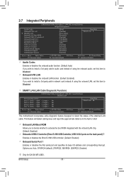
Options are: Auto, 3F8/IRQ4 (default), 2F8/IRQ3, 3E8/IRQ4, 2E8/IRQ3, Disabled. j Only for GA-G41MT-USB3. 2-7 Integrated Peripherals CMOS Setup Utility-Copyright (C) 1984-2011 Award Software Integrated Peripherals Azalia Codec Onboard H/W LAN } SMART LAN Onboard LAN Boot ROM...: Save F6: Fail-Safe Defaults ESC: Exit F1: General Help F7: Optimized Defaults This motherboard incorporates cable diagnostic feature designed to Disabled. BIOS Setup - 30 - Onboard H/W LAN Enables or disables the onboard LAN function. (Default: Enabled) If you to decide whether to Disabled.
Options are: Auto, 3F8/IRQ4 (default), 2F8/IRQ3, 3E8/IRQ4, 2E8/IRQ3, Disabled. j Only for GA-G41MT-USB3. 2-7 Integrated Peripherals CMOS Setup Utility-Copyright (C) 1984-2011 Award Software Integrated Peripherals Azalia Codec Onboard H/W LAN } SMART LAN Onboard LAN Boot ROM...: Save F6: Fail-Safe Defaults ESC: Exit F1: General Help F7: Optimized Defaults This motherboard incorporates cable diagnostic feature designed to Disabled. BIOS Setup - 30 - Onboard H/W LAN Enables or disables the onboard LAN function. (Default: Enabled) If you to decide whether to Disabled.
Manual
Page 31
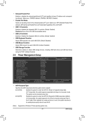
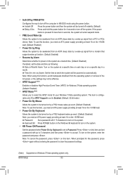
...; ACPI Suspend Type Soft-Off by PWR-BTTN PME Event Wake Up Power On by Ring Resume by Alarm x Date (of the USB functionalities below. BIOS Setup Options are : SPP (Standard Parallel Port) (default), EPP (Enhanced Parallel Port), ECP (Extended Capabilities Port), ECP+EPP. In S3 sleep state, the system appears...
...; ACPI Suspend Type Soft-Off by PWR-BTTN PME Event Wake Up Power On by Ring Resume by Alarm x Date (of the USB functionalities below. BIOS Setup Options are : SPP (Standard Parallel Port) (default), EPP (Enhanced Parallel Port), ECP (Extended Capabilities Port), ECP+EPP. In S3 sleep state, the system appears...
Manual
Page 32
...) Note: you need an ATX power supply providing at a specific time on each day or on a specific day in MS-DOS mode using this item. BIOS Setup - 32 - Time (hh: mm: ss) Alarm: Set the time at least 1A on the +5VSB lead. Press on Windows 7/Vista operating system only. When...
...) Note: you need an ATX power supply providing at a specific time on each day or on a specific day in MS-DOS mode using this item. BIOS Setup - 32 - Time (hh: mm: ss) Alarm: Set the time at least 1A on the +5VSB lead. Press on Windows 7/Vista operating system only. When...


