
Manual
Page 7
.../Intel® Core™ 2 Duo processor/ Intel® Pentium® processor/Intel® Celeron® processor in the LGA775 package (Go to GIGABYTE's website for the latest CPU support list.) ŠŠ L2 cache varies with CPU Front Side Bus ŠŠ 1333/1066/800 MHz FSB ...; 1 x CPU fan header ŠŠ 1 x system fan header ŠŠ 1 x front panel header ŠŠ 1 x front panel audio header ŠŠ 2 x USB 2.0/1.1 headers ŠŠ 1 x parallel port ŠŠ 1 x clearing CMOS jumper "*" The GA-G41MT-D3P adopts All-Solid Capacitor design. - 7 -
.../Intel® Core™ 2 Duo processor/ Intel® Pentium® processor/Intel® Celeron® processor in the LGA775 package (Go to GIGABYTE's website for the latest CPU support list.) ŠŠ L2 cache varies with CPU Front Side Bus ŠŠ 1333/1066/800 MHz FSB ...; 1 x CPU fan header ŠŠ 1 x system fan header ŠŠ 1 x front panel header ŠŠ 1 x front panel audio header ŠŠ 2 x USB 2.0/1.1 headers ŠŠ 1 x parallel port ŠŠ 1 x clearing CMOS jumper "*" The GA-G41MT-D3P adopts All-Solid Capacitor design. - 7 -

Manual
Page 8
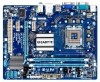
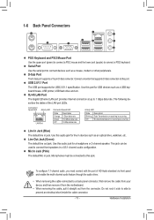
.... Back Panel Connectors ŠŠ 1 x PS/2 keyboard port ŠŠ 1 x PS/2 mouse port ŠŠ 1 x serial port ŠŠ 1 x D-Sub port ŠŠ 4 x USB 2.0/1.1 ports ŠŠ 1 x RJ-45 port ŠŠ 3 x audio jacks (Line In/Line Out/Microphone) I/O ŠŠ iTE IT8718 Hardware ŠŠ System voltage detection...) Operating System ŠŠ Support for Microsoft® Windows 7/Vista/XP Form Factor ŠŠ Micro ATX Form Factor; 24.4cm x 19.4cm * GIGABYTE reserves the right to make any changes to the hardware limitation, you install.
.... Back Panel Connectors ŠŠ 1 x PS/2 keyboard port ŠŠ 1 x PS/2 mouse port ŠŠ 1 x serial port ŠŠ 1 x D-Sub port ŠŠ 4 x USB 2.0/1.1 ports ŠŠ 1 x RJ-45 port ŠŠ 3 x audio jacks (Line In/Line Out/Microphone) I/O ŠŠ iTE IT8718 Hardware ŠŠ System voltage detection...) Operating System ŠŠ Support for Microsoft® Windows 7/Vista/XP Form Factor ŠŠ Micro ATX Form Factor; 24.4cm x 19.4cm * GIGABYTE reserves the right to make any changes to the hardware limitation, you install.
Manual
Page 11
...data transmission or receiving is occurring Line In Jack (Blue) The default line in devices such as a USB keyboard/mouse, USB printer, USB flash drive and etc. USB 2.0/1.1 Port The USB port supports the USB 2.0/1.1 specification. Do not rock it side to side to a back panel connector, first remove the ...device and then remove it from the motherboard. • When removing the cable, pull it straight out from the connector. Use this port for USB devices such as an optical drive, walkman, etc. Use this audio jack for a headphone or 2-channel speaker. D-Sub Port The D-Sub ...
...data transmission or receiving is occurring Line In Jack (Blue) The default line in devices such as a USB keyboard/mouse, USB printer, USB flash drive and etc. USB 2.0/1.1 Port The USB port supports the USB 2.0/1.1 specification. Do not rock it side to side to a back panel connector, first remove the ...device and then remove it from the motherboard. • When removing the cable, pull it straight out from the connector. Use this port for USB devices such as an optical drive, walkman, etc. Use this audio jack for a headphone or 2-channel speaker. D-Sub Port The D-Sub ...

Manual
Page 16
... • Some chassis provide a front panel audio module that has different wire assignments, please contact the chassis manufacturer. 8) F_USB1/F_USB2 (USB Headers) The headers conform to the USB bracket. For purchasing the optional USB bracket, please contact the local dealer. 9 1 10 2 Pin No. 1 2 3 4 5 6 7 8 9 10 Definition Power...+ GND GND No Pin NC • Do not plug the IEEE 1394 bracket (2x5-pin) cable into the USB header. • Prior to installing the USB bracket, be present on each wire instead of the motherboard header. Hardware Installation - 16 - 7) F_AUDIO (Front ...
... • Some chassis provide a front panel audio module that has different wire assignments, please contact the chassis manufacturer. 8) F_USB1/F_USB2 (USB Headers) The headers conform to the USB bracket. For purchasing the optional USB bracket, please contact the local dealer. 9 1 10 2 Pin No. 1 2 3 4 5 6 7 8 9 10 Definition Power...+ GND GND No Pin NC • Do not plug the IEEE 1394 bracket (2x5-pin) cable into the USB header. • Prior to installing the USB bracket, be present on each wire instead of the motherboard header. Hardware Installation - 16 - 7) F_AUDIO (Front ...
Manual
Page 30
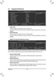
... Software Integrated Peripherals Azalia Codec Onboard H/W LAN } SMART LAN Onboard LAN Boot ROM Onboard Serial Port 1 Onboard Parallel Port Parallel Port Mode USB 1.0 Controller USB 2.0 Controller USB Keyboard Support USB Mouse Support USB Storage Function [Auto] [Enabled] [Press Enter] [Disabled] [3F8/IRQ4] [378/IRQ7] [SPP] [Enabled] [Enabled] [Disabled] [Disabled] [Enabled] Item Help Menu Level ...
... Software Integrated Peripherals Azalia Codec Onboard H/W LAN } SMART LAN Onboard LAN Boot ROM Onboard Serial Port 1 Onboard Parallel Port Parallel Port Mode USB 1.0 Controller USB 2.0 Controller USB Keyboard Support USB Mouse Support USB Storage Function [Auto] [Enabled] [Press Enter] [Disabled] [3F8/IRQ4] [378/IRQ7] [SPP] [Enabled] [Enabled] [Disabled] [Disabled] [Enabled] Item Help Menu Level ...
Manual
Page 31
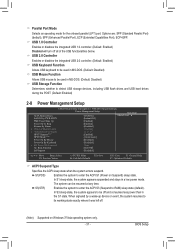
...In S1 sleep state, the system appears suspended and stays in MS-DOS. (Default: Disabled) USB Storage Function Determines whether to detect USB storage devices, including USB flash drives and USB hard drives during the POST. (Default: Enabled) 2-8 Power Management Setup CMOS Setup Utility-Copyright...(default). S1(POS) Enables the system to be resumed at any time. When signaled by Alarm [Disabled] x Date (of the USB functionalities below. Options are: SPP (Standard Parallel Port) (default), EPP (Enhanced Parallel Port), ECP (Extended Capabilities Port), ECP+EPP....
...In S1 sleep state, the system appears suspended and stays in MS-DOS. (Default: Disabled) USB Storage Function Determines whether to detect USB storage devices, including USB flash drives and USB hard drives during the POST. (Default: Enabled) 2-8 Power Management Setup CMOS Setup Utility-Copyright...(default). S1(POS) Enables the system to be resumed at any time. When signaled by Alarm [Disabled] x Date (of the USB functionalities below. Options are: SPP (Standard Parallel Port) (default), EPP (Enhanced Parallel Port), ECP (Extended Capabilities Port), ECP+EPP....


