
Manual
Page 1
GA-G31MF-S2 LGA775 socket motherboard for Intel® CoreTM processor family/ Intel® Pentium® processor family/Intel® Celeron® processor family User's Manual Rev. 1001 12ME-G31MFS2-1001R
GA-G31MF-S2 LGA775 socket motherboard for Intel® CoreTM processor family/ Intel® Pentium® processor family/Intel® Celeron® processor family User's Manual Rev. 1001 12ME-G31MFS2-1001R
Manual
Page 3
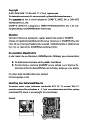
... be reproduced, copied, translated, transmitted, or published in this : "REV: X.X." For example, "REV: 1.0" means the revision of GIGABYTE branded motherboards. The trademarks mentioned in the use GIGABYTE's unique features, read the User's Manual. „ For instructions on how to their respective owners. is the property of documentations: „ For detailed product information, carefully...
... be reproduced, copied, translated, transmitted, or published in this : "REV: X.X." For example, "REV: 1.0" means the revision of GIGABYTE branded motherboards. The trademarks mentioned in the use GIGABYTE's unique features, read the User's Manual. „ For instructions on how to their respective owners. is the property of documentations: „ For detailed product information, carefully...
Manual
Page 6
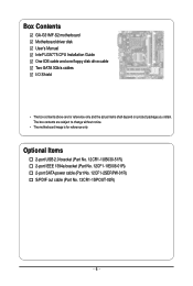
.... 12CF1-1IE008-01R) 2-port SATA power cable (Part No. 12CF1-2SERPW-01R) S/PDIF out cable (Part No. 12CR1-1SPOUT-02R) - 6 - Box Contents GA-G31MF-S2 motherboard Motherboard driver disk User's Manual Intel® LGA775 CPU Installation Guide One IDE cable and one floppy disk drive cable Two SATA 3Gb/s cables I/O Shield • The box...
.... 12CF1-1IE008-01R) 2-port SATA power cable (Part No. 12CF1-2SERPW-01R) S/PDIF out cable (Part No. 12CR1-1SPOUT-02R) - 6 - Box Contents GA-G31MF-S2 motherboard Motherboard driver disk User's Manual Intel® LGA775 CPU Installation Guide One IDE cable and one floppy disk drive cable Two SATA 3Gb/s cables I/O Shield • The box...

Manual
Page 9
... internal connectors on the computer power during the installation process can become damaged as a motherboard, CPU or memory. Prior to installation, carefully read the user's manual and follow these procedures: • Prior to installation, do not remove or break motherboard S/N (Serial Number) sticker or warranty sticker provided by unplugging the power...
... internal connectors on the computer power during the installation process can become damaged as a motherboard, CPU or memory. Prior to installation, carefully read the user's manual and follow these procedures: • Prior to installation, do not remove or break motherboard S/N (Serial Number) sticker or warranty sticker provided by unplugging the power...

Manual
Page 15
... cooler and CPU may damage the CPU. - 15 - Check that the Male and Female push pins are joined closely. (Refer to your CPU cooler installation manual for instructions on the motherboard. If the push pin is inserted as the example cooler.) Step 1: Apply an even and thin layer of thermal grease...
... cooler and CPU may damage the CPU. - 15 - Check that the Male and Female push pins are joined closely. (Refer to your CPU cooler installation manual for instructions on the motherboard. If the push pin is inserted as the example cooler.) Step 1: Apply an even and thin layer of thermal grease...

Manual
Page 18
... seated in the slot and does not rock. • Removing the Card: Gently push back on the lever on your operating system. Carefully read the manual that supports your expansion card in your computer. If necessary, go to BIOS Setup to make any required BIOS changes for your expansion card. •... and unplug the power cord from the power outlet before you begin to the chassis back panel with the expansion card in the expansion slot. 1. GA-G31MF-S2 Motherboard - 18 -
... seated in the slot and does not rock. • Removing the Card: Gently push back on the lever on your operating system. Carefully read the manual that supports your expansion card in your computer. If necessary, go to BIOS Setup to make any required BIOS changes for your expansion card. •... and unplug the power cord from the power outlet before you begin to the chassis back panel with the expansion card in the expansion slot. 1. GA-G31MF-S2 Motherboard - 18 -

Manual
Page 30
... do so may cause damage to the motherboard. • After system restart, go to BIOS Setup to load factory defaults (select Load Optimized Defaults) or manually configure the BIOS settings (refer to Chapter 2, "BIOS Setup," for a few seconds. Open: Normal Short: Clear CMOS Values • Always turn off your computer, be...) CLR_CMOS (Clearing CMOS Jumper) Use this jumper to factory defaults. date information and BIOS configurations) and reset the CMOS values to clear the CMOS values (e.g. GA-G31MF-S2 Motherboard - 30 -
... do so may cause damage to the motherboard. • After system restart, go to BIOS Setup to load factory defaults (select Load Optimized Defaults) or manually configure the BIOS settings (refer to Chapter 2, "BIOS Setup," for a few seconds. Open: Normal Short: Clear CMOS Values • Always turn off your computer, be...) CLR_CMOS (Clearing CMOS Jumper) Use this jumper to factory defaults. date information and BIOS configurations) and reset the CMOS values to clear the CMOS values (e.g. GA-G31MF-S2 Motherboard - 30 -

Manual
Page 35
...only), month, date and year. Select the desired field and use the up arrow or down arrow key to set the date. Allows you to manually enter the specifications of the three methods below : • Auto Lets BIOS automatically detect IDE/SATA devices during the POST. (Default) • ...this channel. Extended IDE Drive Configure your IDE/SATA devices by using one of the two methods below : • Auto • None • Manual Access Mode Lets BIOS automatically detect IDE/SATA devices during the POST. (Default) If no IDE/SATA devices are used , set to autodetect the ...
...only), month, date and year. Select the desired field and use the up arrow or down arrow key to set the date. Allows you to manually enter the specifications of the three methods below : • Auto Lets BIOS automatically detect IDE/SATA devices during the POST. (Default) • ...this channel. Extended IDE Drive Configure your IDE/SATA devices by using one of the two methods below : • Auto • None • Manual Access Mode Lets BIOS automatically detect IDE/SATA devices during the POST. (Default) If no IDE/SATA devices are used , set to autodetect the ...

Manual
Page 36
... None, 360K/5.25", 1.2M/5.25", 720K/3.5", 1.44M/3.5", 2.88M/3.5". Head Number of sectors. If you wish to enter the parameters manually, refer to selects the type of floppy disk drive installed in your hard drive specifications. Base Memory Also called conventional memory. Sector Number... system will stop for all other errors. All, But Keyboard The system boot will not stop for a keyboard error but stop . GA-G31MF-S2 Motherboard - 36 - Capacity Approximate capacity of extended memory. Typically, 640 KB will stop for any error. Landing Zone Landing zone. ...
... None, 360K/5.25", 1.2M/5.25", 720K/3.5", 1.44M/3.5", 2.88M/3.5". Head Number of sectors. If you wish to enter the parameters manually, refer to selects the type of floppy disk drive installed in your hard drive specifications. Base Memory Also called conventional memory. Sector Number... system will stop for all other errors. All, But Keyboard The system boot will not stop for a keyboard error but stop . GA-G31MF-S2 Motherboard - 36 - Capacity Approximate capacity of extended memory. Typically, 640 KB will stop for any error. Landing Zone Landing zone. ...

Manual
Page 39
... PATA IDE Set to operate in PATA mode. Disabled Disables the integrated IDE controller when Non-Combined is automatically configured to Combined mode, you can manually re-configure it to Enhanced mode as needed. (Default) Combined Sets all SATA devices to USB Controller USB 2.0 Controller USB Keyboard Support USB Mouse Support...
... PATA IDE Set to operate in PATA mode. Disabled Disables the integrated IDE controller when Non-Combined is automatically configured to Combined mode, you can manually re-configure it to Enhanced mode as needed. (Default) Combined Sets all SATA devices to USB Controller USB 2.0 Controller USB Keyboard Support USB Mouse Support...

Manual
Page 46
...and reduce the useful life of these components. Options are: Auto (default), Fast, Turbo. CPU Frequency Displays the current operating CPU frequency. GA-G31MF-S2 Motherboard - 46 - The item is present only if a CPU with unlocked clock ratio is installed. Note: If your system fails to...Control FSB OverVoltage Control CPU Voltage Control Normal CPU Vcore [Auto] [7X] [+0.5] 2.50GHz(333x7.5) [Disabled] 333 [Auto] [Standard] [Auto] 800 ******** [Manual] [Normal] [Normal] [Normal] 1.22500V Item Help Menu Level` KLJI: Move Enter: Select F5: Previous Values +/-/PU/PD: Value F10: Save F6: ...
...and reduce the useful life of these components. Options are: Auto (default), Fast, Turbo. CPU Frequency Displays the current operating CPU frequency. GA-G31MF-S2 Motherboard - 46 - The item is present only if a CPU with unlocked clock ratio is installed. Note: If your system fails to...Control FSB OverVoltage Control CPU Voltage Control Normal CPU Vcore [Auto] [7X] [+0.5] 2.50GHz(333x7.5) [Disabled] 333 [Auto] [Standard] [Auto] 800 ******** [Manual] [Normal] [Normal] [Normal] 1.22500V Item Help Menu Level` KLJI: Move Enter: Select F5: Previous Values +/-/PU/PD: Value F10: Save F6: ...

Manual
Page 47
... CPU voltage may result in damage to set the Front Side Bus voltage. For a 1066 MHz FSB CPU, set this item to manually set this item to manually set memory voltage. Standard Lets the system operate at its basic performance level. (Default) Turbo Lets the system operate at its good ...266 MHz. The adjustable range is from 100 MHz to 0.3V at 0.1V increment. System Memory Multiplier (SPD) Allows you to 150 MHz. Manual allows all voltage control items below to be set the system voltages. The adjustable range is highly recommended that is the normal operating frequency of...
... CPU voltage may result in damage to set the Front Side Bus voltage. For a 1066 MHz FSB CPU, set this item to manually set this item to manually set memory voltage. Standard Lets the system operate at its basic performance level. (Default) Turbo Lets the system operate at its good ...266 MHz. The adjustable range is from 100 MHz to 0.3V at 0.1V increment. System Memory Multiplier (SPD) Allows you to 150 MHz. Manual allows all voltage control items below to be set the system voltages. The adjustable range is highly recommended that is the normal operating frequency of...

Manual
Page 53
3-4 Hardware Information This page provides information about the hardware devices on this motherboard. 3-5 Contact Us Check the contacts information of the GIGABYTE headquarter in Taiwan and the overseas branch offices on the last page of this manual. - 53 - Drivers Installation
3-4 Hardware Information This page provides information about the hardware devices on this motherboard. 3-5 Contact Us Check the contacts information of the GIGABYTE headquarter in Taiwan and the overseas branch offices on the last page of this manual. - 53 - Drivers Installation

Manual
Page 64
...where you save the BIOS update file (e.g. G31MFS2. Select Load Optimized Defaults and press to load BIOS defaults. 3. F1) obtained from GIGABYTE's website and follow the instructions in "Update the BIOS without Using the Internet Update Function Click Update New BIOS Step 1: Click Update ...click OK. Step 4: As the system reboots, press to enter the BIOS Setup program. GA-G31MF-S2 Motherboard - 64 - Step 3: First make sure the model name on the @BIOS server site, please manually download the BIOS update file from the Internet or through other source. Step 2: In the ...
...where you save the BIOS update file (e.g. G31MFS2. Select Load Optimized Defaults and press to load BIOS defaults. 3. F1) obtained from GIGABYTE's website and follow the instructions in "Update the BIOS without Using the Internet Update Function Click Update New BIOS Step 1: Click Update ...click OK. Step 4: As the system reboots, press to enter the BIOS Setup program. GA-G31MF-S2 Motherboard - 64 - Step 3: First make sure the model name on the @BIOS server site, please manually download the BIOS update file from the Internet or through other source. Step 2: In the ...

Manual
Page 78
... at the Customer Care number listed in your product's user's manual and we at the time of life" product. GA-G31MF-S2 Motherboard - 78 - We believe that the information contained herein was accurate in all GIGABYTE motherboards fulfill European Union regulations for recycling. Š If you..., which indicates that this product must not be marked, collected separately, and disposed of Hazardous Substances (RoHS) Directive Statement GIGABYTE products have been carefully selected to develop products that the information in this document is recycled in this text. Instead, the...
... at the Customer Care number listed in your product's user's manual and we at the time of life" product. GA-G31MF-S2 Motherboard - 78 - We believe that the information contained herein was accurate in all GIGABYTE motherboards fulfill European Union regulations for recycling. Š If you..., which indicates that this product must not be marked, collected separately, and disposed of Hazardous Substances (RoHS) Directive Statement GIGABYTE products have been carefully selected to develop products that the information in this document is recycled in this text. Instead, the...


