
Manual
Page 4
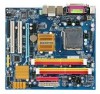
Table of Contents Box Contents ...6 OptionalItems ...6 GA-G31MF-S2 Motherboard Layout 7 Block Diagram ...8 Chapter 1 Hardware Installation 9 1-1 Installation Precautions 9 1-2 Product Specifications 10 1-3 Installing the CPU and CPU Cooler 13 1-3-1 Installing the CPU 13 1-3-2 Installing the CPU Cooler 15 1-4 Installing the Memory 16 1-4-1 Dual Channel Memory Configuration 16 1-4-2 Installing a Memory 17 1-5 Installing an Expansion Card 18 1-6 Back Panel Connectors 19...
Table of Contents Box Contents ...6 OptionalItems ...6 GA-G31MF-S2 Motherboard Layout 7 Block Diagram ...8 Chapter 1 Hardware Installation 9 1-1 Installation Precautions 9 1-2 Product Specifications 10 1-3 Installing the CPU and CPU Cooler 13 1-3-1 Installing the CPU 13 1-3-2 Installing the CPU Cooler 15 1-4 Installing the Memory 16 1-4-1 Dual Channel Memory Configuration 16 1-4-2 Installing a Memory 17 1-5 Installing an Expansion Card 18 1-6 Back Panel Connectors 19...
Manual
Page 6
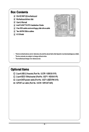
.... 12CF1-2SERPW-01R) S/PDIF out cable (Part No. 12CR1-1SPOUT-02R) - 6 - The box contents are for reference only. Box Contents GA-G31MF-S2 motherboard Motherboard driver disk User's Manual Intel® LGA775 CPU Installation Guide One IDE cable and one floppy disk drive cable Two SATA 3Gb/s cables I/O Shield • The box contents above...
.... 12CF1-2SERPW-01R) S/PDIF out cable (Part No. 12CR1-1SPOUT-02R) - 6 - The box contents are for reference only. Box Contents GA-G31MF-S2 motherboard Motherboard driver disk User's Manual Intel® LGA775 CPU Installation Guide One IDE cable and one floppy disk drive cable Two SATA 3Gb/s cables I/O Shield • The box contents above...

Manual
Page 8
Block Diagram 1 PCI Express x16 D-Sub PCIe CLK (100 MHz) PCI Express x16 1 PCI Express x1 LAN PCIe CLK (100 MHz) x1 RJ45 RTL8111C PCI Express Bus PCI Bus TSB43AB23 2 IEEE 1394a LGA775 Processor Host Interface Intel® G31 CPU CLK+/(333/266/200 MHz) DDR2 800/667 MHz Dual Channel Memory GMCH CLK (333/266/200 MHz) Intel® ICH7 CODEC BIOS ATA-100/66/33 IDE Channel 4 SATA 3Gb/s 8 USB Ports IT8718 Floppy LPT Port COM Port PS/2 KB/Mouse 2 PCI PCI CLK (33 MHz) MIC (Center/Subwoofer Speaker Out) Line-Out(Front Speaker Out) Line-In(Rear Speaker Out) SPDIF Out - 8 -
Block Diagram 1 PCI Express x16 D-Sub PCIe CLK (100 MHz) PCI Express x16 1 PCI Express x1 LAN PCIe CLK (100 MHz) x1 RJ45 RTL8111C PCI Express Bus PCI Bus TSB43AB23 2 IEEE 1394a LGA775 Processor Host Interface Intel® G31 CPU CLK+/(333/266/200 MHz) DDR2 800/667 MHz Dual Channel Memory GMCH CLK (333/266/200 MHz) Intel® ICH7 CODEC BIOS ATA-100/66/33 IDE Channel 4 SATA 3Gb/s 8 USB Ports IT8718 Floppy LPT Port COM Port PS/2 KB/Mouse 2 PCI PCI CLK (33 MHz) MIC (Center/Subwoofer Speaker Out) Line-Out(Front Speaker Out) Line-In(Rear Speaker Out) SPDIF Out - 8 -

Manual
Page 9
... 1 Hardware Installation 1-1 Installation Precautions The motherboard contains numerous delicate electronic circuits and components which can lead to damage to system components as well as a motherboard, CPU or memory. Hardware Installation If you do not allow screws to come in a high-temperature environment. • Turning on the computer power during the installation...
... 1 Hardware Installation 1-1 Installation Precautions The motherboard contains numerous delicate electronic circuits and components which can lead to damage to system components as well as a motherboard, CPU or memory. Hardware Installation If you do not allow screws to come in a high-temperature environment. • Turning on the computer power during the installation...

Manual
Page 10
... bracket connected to the internal IEEE 1394a header) Š Integrated in the LGA 775 package (Go to GIGABYTE's website for the latest CPU support list.) Š L2 cache varies with CPU Š 1333/1066/800 MHz FSB Š North Bridge: Intel® G31 Express Chipset Š South..., SATAII3) supporting up to 4 SATA 3Gb/s devices Š iTE IT8718 chip: - 1 x floppy disk drive connector supporting up to the internal USB headers) GA-G31MF-S2 Motherboard - 10 - TSB43AB23 chip Š Up to 2 IEEE 1394a ports (1 on the back panel, 1 via the USB brackets connected to 1 floppy disk drive Š...
... bracket connected to the internal IEEE 1394a header) Š Integrated in the LGA 775 package (Go to GIGABYTE's website for the latest CPU support list.) Š L2 cache varies with CPU Š 1333/1066/800 MHz FSB Š North Bridge: Intel® G31 Express Chipset Š South..., SATAII3) supporting up to 4 SATA 3Gb/s devices Š iTE IT8718 chip: - 1 x floppy disk drive connector supporting up to the internal USB headers) GA-G31MF-S2 Motherboard - 10 - TSB43AB23 chip Š Up to 2 IEEE 1394a ports (1 on the back panel, 1 via the USB brackets connected to 1 floppy disk drive Š...

Manual
Page 11
...Š 1 x 4-pin ATX 12V power connector Š 1 x floppy disk drive connector Š 1 x IDE connector Š 4 x SATA 3Gb/s connectors Š 1 x CPU fan header Š 1 x system fan header Š 1 x front panel header Š 1 x front panel audio header Š 1 x CD In connector Š 1 x... Out/Microphone) I/O Controller Š iTE IT8718 chip Hardware Monitor Š System voltage detection Š CPU temperature detection Š CPU/System fan speed detection Š CPU overheating warning Š CPU/System fan fail warning Š CPU fan speed control (Note 2) - 11 -
...Š 1 x 4-pin ATX 12V power connector Š 1 x floppy disk drive connector Š 1 x IDE connector Š 4 x SATA 3Gb/s connectors Š 1 x CPU fan header Š 1 x system fan header Š 1 x front panel header Š 1 x front panel audio header Š 1 x CD In connector Š 1 x... Out/Microphone) I/O Controller Š iTE IT8718 chip Hardware Monitor Š System voltage detection Š CPU temperature detection Š CPU/System fan speed detection Š CPU overheating warning Š CPU/System fan fail warning Š CPU fan speed control (Note 2) - 11 -

Manual
Page 12
GA-G31MF-S2 Motherboard - 12 - BIOS Unique Features Operating System Form Factor Š 1 x 8 Mbit flash Š Use of licensed AWARD BIOS Š PnP 1.0a, DMI 2.0, SM BIOS 2.4, ACPI 1.... operating system limitation, when more than 4 GB of physical memory is installed, the actual memory size displayed will be less than 4 GB. (Note 2) Whether the CPU fan speed control function is supported will depend on the CPU cooler you install. (Note 3) Available functions in Easytune may differ by motherboard model.
GA-G31MF-S2 Motherboard - 12 - BIOS Unique Features Operating System Form Factor Š 1 x 8 Mbit flash Š Use of licensed AWARD BIOS Š PnP 1.0a, DMI 2.0, SM BIOS 2.4, ACPI 1.... operating system limitation, when more than 4 GB of physical memory is installed, the actual memory size displayed will be less than 4 GB. (Note 2) Whether the CPU fan speed control function is supported will depend on the CPU cooler you install. (Note 3) Available functions in Easytune may differ by motherboard model.

Manual
Page 13
... guidelines before installing the CPU to your hardware specifications including the CPU, graphics card, memory, hard drive, etc. 1-3-1 Installing the CPU A. mended that the motherboard supports the CPU. (Go to GIGABYTE's website for the peripherals. LGA775 CPU Socket Alignment Key LGA 775 CPU Alignment Key Pin One Corner of the CPU. Hardware Installation The CPU cannot be set the...
... guidelines before installing the CPU to your hardware specifications including the CPU, graphics card, memory, hard drive, etc. 1-3-1 Installing the CPU A. mended that the motherboard supports the CPU. (Go to GIGABYTE's website for the peripherals. LGA775 CPU Socket Alignment Key LGA 775 CPU Alignment Key Pin One Corner of the CPU. Hardware Installation The CPU cannot be set the...

Manual
Page 14
... pin one corner of the CPU socket (or you may align the CPU notches with your thumb and index fingers. GA-G31MF-S2 Motherboard - 14 - CPU Socket Lever Step 1: Completely raise the CPU socket lever. Step 3: Lift the metal load plate on the CPU socket. Follow the steps below to the CPU. Step 5: Once the CPU is properly inserted, replace...
... pin one corner of the CPU socket (or you may align the CPU notches with your thumb and index fingers. GA-G31MF-S2 Motherboard - 14 - CPU Socket Lever Step 1: Completely raise the CPU socket lever. Step 3: Lift the metal load plate on the CPU socket. Follow the steps below to the CPU. Step 5: Once the CPU is properly inserted, replace...

Manual
Page 15
...on the motherboard. Check that the Male and Female push pins are joined closely. (Refer to install.) Step 3: Place the cooler atop the CPU, aligning the four push pins through the pin holes on the motherboard. Direction of the Arrow Sign on the Male Push Pin Male Push Pin... manual for instructions on the push pins diagonally. Push down each push pin. Use extreme care when removing the CPU cooler because the thermal grease/tape between the CPU cooler and CPU may damage the CPU. - 15 - Step 4: You should hear a "click" when pushing down on installing the cooler.) Step 5: After...
...on the motherboard. Check that the Male and Female push pins are joined closely. (Refer to install.) Step 3: Place the cooler atop the CPU, aligning the four push pins through the pin holes on the motherboard. Direction of the Arrow Sign on the Male Push Pin Male Push Pin... manual for instructions on the push pins diagonally. Push down each push pin. Use extreme care when removing the CPU cooler because the thermal grease/tape between the CPU cooler and CPU may damage the CPU. - 15 - Step 4: You should hear a "click" when pushing down on installing the cooler.) Step 5: After...

Manual
Page 22
... that can supply enough stable power to all devices are properly installed. The power connector possesses a foolproof design. Connect the power supply cable to the CPU. If a power supply is used (400W or greater). Before connecting the power connector, first make sure the power supply is turned off and all ... 16 17 18 19 20 21 22 23 24 Definition 3.3V -12V GND PS_ON(soft On/Off) GND GND GND -5V +5V +5V +5V GND GA-G31MF-S2 Motherboard - 22 - Do not insert the power supply cable into pins under the protective cover when using a 2x12 power supply, remove the protective cover from...
... that can supply enough stable power to all devices are properly installed. The power connector possesses a foolproof design. Connect the power supply cable to the CPU. If a power supply is used (400W or greater). Before connecting the power connector, first make sure the power supply is turned off and all ... 16 17 18 19 20 21 22 23 24 Definition 3.3V -12V GND PS_ON(soft On/Off) GND GND GND -5V +5V +5V +5V GND GA-G31MF-S2 Motherboard - 22 - Do not insert the power supply cable into pins under the protective cover when using a 2x12 power supply, remove the protective cover from...

Manual
Page 23
... fan cables to the fan headers to connect a floppy disk drive. Before connecting a floppy disk drive, be sure to locate pin 1 of a CPU fan with color-coded power connector wires. When connecting a fan cable, be sure to connect it is the ground wire. The motherboard supports... which requires the use of the connector and the floppy disk drive cable. Hardware Installation The types of the cable is used to prevent your CPU and system from overheating. The pin 1 of floppy disk drives supported are not configuration jumper blocks. Each fan header supplies a +12V power ...
... fan cables to the fan headers to connect a floppy disk drive. Before connecting a floppy disk drive, be sure to locate pin 1 of a CPU fan with color-coded power connector wires. When connecting a fan cable, be sure to connect it is the ground wire. The motherboard supports... which requires the use of the connector and the floppy disk drive cable. Hardware Installation The types of the cable is used to prevent your CPU and system from overheating. The pin 1 of floppy disk drives supported are not configuration jumper blocks. Each fan header supplies a +12V power ...

Manual
Page 34
... confirmation message will exit BIOS Setup. (Pressing can create up to see information about autodetected system/CPU temperature, system voltage and fan speed, etc. „ MB Intelligent Tweaker(M.I.T.) Use this task.) GA-G31MF-S2 Motherboard - 34 - „ The Functions of the and keys (For the Main Menu Only...the system boot, etc. „ Advanced BIOS Features Use this menu to configure the device boot order, advanced features available on the CPU, and the primary display adapter. „ Integrated Peripherals Use this menu to configure all peripheral devices, such as IDE, SATA, USB...
... confirmation message will exit BIOS Setup. (Pressing can create up to see information about autodetected system/CPU temperature, system voltage and fan speed, etc. „ MB Intelligent Tweaker(M.I.T.) Use this task.) GA-G31MF-S2 Motherboard - 34 - „ The Functions of the and keys (For the Main Menu Only...the system boot, etc. „ Advanced BIOS Features Use this menu to configure the device boot order, advanced features available on the CPU, and the primary display adapter. „ Integrated Peripherals Use this menu to configure all peripheral devices, such as IDE, SATA, USB...

Manual
Page 37
...features, please visit Intel's website. - 37 - Press to exit this item to 3 (Note) No-Execute Memory Protect (Note) CPU Enhanced Halt (C1E) (Note) CPU Thermal Monitor 2(TM2) (Note) CPU EIST Function (Note) Virtualization Technology (Note) Init Display First Onboard VGA [Disabled] [Disabled] [Enabled] [Enabled] [Enabled] [Enabled...or the minus key (or ) to issue warnings when a third party hardware monitor utility is present only if you install a CPU that supports this item, set this item to Enabled for entering the BIOS Setup program. (Default) System A password is required every...
...features, please visit Intel's website. - 37 - Press to exit this item to 3 (Note) No-Execute Memory Protect (Note) CPU Enhanced Halt (C1E) (Note) CPU Thermal Monitor 2(TM2) (Note) CPU EIST Function (Note) Virtualization Technology (Note) Init Display First Onboard VGA [Disabled] [Disabled] [Enabled] [Enabled] [Enabled] [Enabled...or the minus key (or ) to issue warnings when a third party hardware monitor utility is present only if you install a CPU that supports this item, set this item to Enabled for entering the BIOS Setup program. (Default) System A password is required every...

Manual
Page 38
... Size Frame buffer size is installed. For more information about Intel CPUs' unique features, please visit Intel's website. GA-G31MF-S2 Motherboard - 38 - With virtualization, one computer system can dynamically and effectively lower the CPU voltage and core frequency to run multiple operating systems and applications in system halt state. Options are: 8MB+1~2MB...
... Size Frame buffer size is installed. For more information about Intel CPUs' unique features, please visit Intel's website. GA-G31MF-S2 Motherboard - 38 - With virtualization, one computer system can dynamically and effectively lower the CPU voltage and core frequency to run multiple operating systems and applications in system halt state. Options are: 8MB+1~2MB...

Manual
Page 45
... PC Health Status Reset Case Open Status Case Opened Vcore DDR18V +3.3V +12V Current CPU Temperature Current CPU FAN Speed Current SYSTEM FAN Speed CPU Warning Temperature CPU FAN Fail Warning SYSTEM FAN Fail Warning CPU Smart FAN Control [Disabled] No 1.300V 1.808V 3.424V 12.175V 47oC 3375 RPM...with EasyTune based on system requirements. Current Voltage(V) Vcore/DDR18V/+3.3V/+12V Displays the current system voltages. Current CPU/SYSTEM FAN Speed (RPM) Displays current CPU/system fan speed. Enabled clears the record of previous chassis intrusion status and the Case Opened field will show...
... PC Health Status Reset Case Open Status Case Opened Vcore DDR18V +3.3V +12V Current CPU Temperature Current CPU FAN Speed Current SYSTEM FAN Speed CPU Warning Temperature CPU FAN Fail Warning SYSTEM FAN Fail Warning CPU Smart FAN Control [Disabled] No 1.300V 1.808V 3.424V 12.175V 47oC 3375 RPM...with EasyTune based on system requirements. Current Voltage(V) Vcore/DDR18V/+3.3V/+12V Displays the current system voltages. Current CPU/SYSTEM FAN Speed (RPM) Displays current CPU/system fan speed. Enabled clears the record of previous chassis intrusion status and the Case Opened field will show...

Manual
Page 46
... Frequency (Mhz) Performance Enhance System Memory Multiplier (SPD) Memory Frequency (Mhz) 800 ******** System Voltage Optimized System Voltage Control DDR2 OverVoltage Control FSB OverVoltage Control CPU Voltage Control Normal CPU Vcore [Auto] [7X] [+0.5] 2.50GHz(333x7.5) [Disabled] 333 [Auto] [Standard] [Auto] 800 ******** [Manual] [Normal] [Normal] [Normal] 1.22500V Item Help... ESC: Exit F1: General Help F7: Optimized Defaults • Incorrectly doing overclock/overvoltage may result in system's failure to boot. GA-G31MF-S2 Motherboard - 46 - mode based on system configurations.
... Frequency (Mhz) Performance Enhance System Memory Multiplier (SPD) Memory Frequency (Mhz) 800 ******** System Voltage Optimized System Voltage Control DDR2 OverVoltage Control FSB OverVoltage Control CPU Voltage Control Normal CPU Vcore [Auto] [7X] [+0.5] 2.50GHz(333x7.5) [Disabled] 333 [Auto] [Standard] [Auto] 800 ******** [Manual] [Normal] [Normal] [Normal] 1.22500V Item Help... ESC: Exit F1: General Help F7: Optimized Defaults • Incorrectly doing overclock/overvoltage may result in system's failure to boot. GA-G31MF-S2 Motherboard - 46 - mode based on system configurations.

Manual
Page 47
...System Memory Multiplier settings. ******** System Voltage Optimized ******** System Voltage Control Determines whether to manually set the system voltages. For a 1333 MHz FSB CPU, set this item to 200 MHz. Important It is highly recommended that is from 90 MHz to 150 MHz. Auto lets BIOS automatically set... increment. the second is from 100 MHz to 700 MHz. Note: Increasing memory voltage may result in accordance with the CPU specifications. For a 1066 MHz FSB CPU, set this item to 266 MHz. PCI Express Frequency (Mhz) Allows you to set memory voltage. Normal Supplies the FSB...
...System Memory Multiplier settings. ******** System Voltage Optimized ******** System Voltage Control Determines whether to manually set the system voltages. For a 1333 MHz FSB CPU, set this item to 200 MHz. Important It is highly recommended that is from 90 MHz to 150 MHz. Auto lets BIOS automatically set... increment. the second is from 100 MHz to 700 MHz. Note: Increasing memory voltage may result in accordance with the CPU specifications. For a 1066 MHz FSB CPU, set this item to 266 MHz. PCI Express Frequency (Mhz) Allows you to set memory voltage. Normal Supplies the FSB...

Manual
Page 65
... PC HEALTH setting page Confirmation/execution button Toggles among Easy Mode, Advanced Mode, and Graphics Mode Displays the CPU frequency Shows the supported function(s) Go to GIGABYTE website to update EasyTune 5 Pro Opens EasyTune 5 Pro help file Quits or minimizes the EasyTune 5 Pro ...interface Performance Enhancement Incorrectly doing overclock/overvoltage may result in damage to CPU, chipset, or memory and reduce the useful life of these ...
... PC HEALTH setting page Confirmation/execution button Toggles among Easy Mode, Advanced Mode, and Graphics Mode Displays the CPU frequency Shows the supported function(s) Go to GIGABYTE website to update EasyTune 5 Pro Opens EasyTune 5 Pro help file Quits or minimizes the EasyTune 5 Pro ...interface Performance Enhancement Incorrectly doing overclock/overvoltage may result in damage to CPU, chipset, or memory and reduce the useful life of these ...

Manual
Page 76
... connected to save changes and exit BIOS Setup. Secure the CPU No cooler on the power to start the computer. No Correctly insert the memory into the memory socket. Make sure the motherboard does not short-... the memory is attached to enter BIOS Setup. No Check if the CPU cooler is installed properly on the memory slot. Yes Insert the graphics card. The problem is verified and solved. Connect the CPU cooler power cable to solve the problem. Press to the CPU securely. Turn on the CPU. A (Continued...) GA-G31MF-S2 Motherboard - 76 -
... connected to save changes and exit BIOS Setup. Secure the CPU No cooler on the power to start the computer. No Correctly insert the memory into the memory socket. Make sure the motherboard does not short-... the memory is attached to enter BIOS Setup. No Check if the CPU cooler is installed properly on the memory slot. Yes Insert the graphics card. The problem is verified and solved. Connect the CPU cooler power cable to solve the problem. Press to the CPU securely. Turn on the CPU. A (Continued...) GA-G31MF-S2 Motherboard - 76 -


