Manual
Page 3
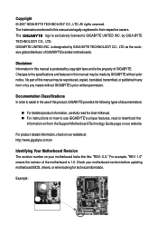
... revision before updating motherboard BIOS, drivers, or when looking for technical information. Documentation Classifications In order to assist in this manual may be reproduced, copied, translated, transmitted, or published in this manual are legally registered to GIGABYTE UNITED INC. Example: Disclaimer... and features in any form or by any means without prior notice. No part of the motherboard is designated by GIGABYTE without GIGABYTE's prior written permission. is 1.0. Check your motherboard looks like this: "REV: X.X." The trademarks mentioned in this ...
... revision before updating motherboard BIOS, drivers, or when looking for technical information. Documentation Classifications In order to assist in this manual may be reproduced, copied, translated, transmitted, or published in this manual are legally registered to GIGABYTE UNITED INC. Example: Disclaimer... and features in any form or by any means without prior notice. No part of the motherboard is designated by GIGABYTE without GIGABYTE's prior written permission. is 1.0. Check your motherboard looks like this: "REV: X.X." The trademarks mentioned in this ...

Manual
Page 4
Table of Contents Box Contents ...6 OptionalItems ...6 GA-G31MF-S2 Motherboard Layout 7 Block Diagram ...8 Chapter 1 Hardware Installation 9 1-1 Installation Precautions 9 1-2 Product Specifications 10 1-3 Installing the CPU and CPU Cooler 13... Memory 17 1-5 Installing an Expansion Card 18 1-6 Back Panel Connectors 19 1-7 Internal Connectors 21 Chapter 2 BIOS Setup 31 2-1 Startup Screen 32 2-2 The Main Menu 33 2-3 Standard CMOS Features 35 2-4 Advanced BIOS Features 37 2-5 IntegratedPeripherals 39 2-6 Power Management Setup 42 2-7 PnP/PCI Configurations 44 2-8 PC Health Status ...
Table of Contents Box Contents ...6 OptionalItems ...6 GA-G31MF-S2 Motherboard Layout 7 Block Diagram ...8 Chapter 1 Hardware Installation 9 1-1 Installation Precautions 9 1-2 Product Specifications 10 1-3 Installing the CPU and CPU Cooler 13... Memory 17 1-5 Installing an Expansion Card 18 1-6 Back Panel Connectors 19 1-7 Internal Connectors 21 Chapter 2 BIOS Setup 31 2-1 Startup Screen 32 2-2 The Main Menu 33 2-3 Standard CMOS Features 35 2-4 Advanced BIOS Features 37 2-5 IntegratedPeripherals 39 2-6 Power Management Setup 42 2-7 PnP/PCI Configurations 44 2-8 PC Health Status ...

Manual
Page 5
... 52 3-3 Driver CD Information 52 3-4 Hardware Information 53 3-5 Contact Us ...53 Chapter 4 Unique Features 55 4-1 Xpress Recovery2 55 4-2 BIOS Update Utilities 60 4-2-1 Updating the BIOS with the Q-Flash Utility 60 4-2-2 Updating the BIOS with the @BIOS Utility 63 4-3 EasyTune 5 Pro 65 4-4 Windows Vista ReadyBoost 66 Chapter 5 Appendix ...67 5-1 ConfiguringAudio Input and Output 67 5-1-1 Configuring...
... 52 3-3 Driver CD Information 52 3-4 Hardware Information 53 3-5 Contact Us ...53 Chapter 4 Unique Features 55 4-1 Xpress Recovery2 55 4-2 BIOS Update Utilities 60 4-2-1 Updating the BIOS with the Q-Flash Utility 60 4-2-2 Updating the BIOS with the @BIOS Utility 63 4-3 EasyTune 5 Pro 65 4-4 Windows Vista ReadyBoost 66 Chapter 5 Appendix ...67 5-1 ConfiguringAudio Input and Output 67 5-1-1 Configuring...

Manual
Page 8
Block Diagram 1 PCI Express x16 D-Sub PCIe CLK (100 MHz) PCI Express x16 1 PCI Express x1 LAN PCIe CLK (100 MHz) x1 RJ45 RTL8111C PCI Express Bus PCI Bus TSB43AB23 2 IEEE 1394a LGA775 Processor Host Interface Intel® G31 CPU CLK+/(333/266/200 MHz) DDR2 800/667 MHz Dual Channel Memory GMCH CLK (333/266/200 MHz) Intel® ICH7 CODEC BIOS ATA-100/66/33 IDE Channel 4 SATA 3Gb/s 8 USB Ports IT8718 Floppy LPT Port COM Port PS/2 KB/Mouse 2 PCI PCI CLK (33 MHz) MIC (Center/Subwoofer Speaker Out) Line-Out(Front Speaker Out) Line-In(Rear Speaker Out) SPDIF Out - 8 -
Block Diagram 1 PCI Express x16 D-Sub PCIe CLK (100 MHz) PCI Express x16 1 PCI Express x1 LAN PCIe CLK (100 MHz) x1 RJ45 RTL8111C PCI Express Bus PCI Bus TSB43AB23 2 IEEE 1394a LGA775 Processor Host Interface Intel® G31 CPU CLK+/(333/266/200 MHz) DDR2 800/667 MHz Dual Channel Memory GMCH CLK (333/266/200 MHz) Intel® ICH7 CODEC BIOS ATA-100/66/33 IDE Channel 4 SATA 3Gb/s 8 USB Ports IT8718 Floppy LPT Port COM Port PS/2 KB/Mouse 2 PCI PCI CLK (33 MHz) MIC (Center/Subwoofer Speaker Out) Line-Out(Front Speaker Out) Line-In(Rear Speaker Out) SPDIF Out - 8 -

Manual
Page 12
...Operating System Form Factor Š 1 x 8 Mbit flash Š Use of licensed AWARD BIOS Š PnP 1.0a, DMI 2.0, SM BIOS 2.4, ACPI 1.0b Š Support for @BIOS Š Support for Download Center Š Support for Q-Flash Š Support for EasyTune ...(Note 3) Š Support for Xpress Install Š Support for Xpress Recovery2 Š Support for Virtual Dual BIOS Š Support for Microsoft® Windows® Vista/XP/2000 Š Micro ATX Form Factor; 24.4cm x 22cm ... 3) Available functions in Easytune may differ by motherboard model. GA-G31MF-S2 Motherboard - 12 -
...Operating System Form Factor Š 1 x 8 Mbit flash Š Use of licensed AWARD BIOS Š PnP 1.0a, DMI 2.0, SM BIOS 2.4, ACPI 1.0b Š Support for @BIOS Š Support for Download Center Š Support for Q-Flash Š Support for EasyTune ...(Note 3) Š Support for Xpress Install Š Support for Xpress Recovery2 Š Support for Virtual Dual BIOS Š Support for Microsoft® Windows® Vista/XP/2000 Š Micro ATX Form Factor; 24.4cm x 22cm ... 3) Available functions in Easytune may differ by motherboard model. GA-G31MF-S2 Motherboard - 12 -

Manual
Page 16
...SS - - 1-4 Installing the Memory Read the following guidelines before you are installed, a message which says memory is installed, the BIOS will double the original memory bandwidth. When enabling Dual Channel mode with double-sided memory modules to prevent system's failure to start ...speed, and chips be populated and remain in Dual Channel mode. 1. A memory module can be used . (Go to GIGABYTE's website for optimum performance. 3. DS/SS - - GA-G31MF-S2 Motherboard - 16 - DDRII1 and DDRII2) with two or four memory modules, it is recommended that memory of the same ...
...SS - - 1-4 Installing the Memory Read the following guidelines before you are installed, a message which says memory is installed, the BIOS will double the original memory bandwidth. When enabling Dual Channel mode with double-sided memory modules to prevent system's failure to start ...speed, and chips be populated and remain in Dual Channel mode. 1. A memory module can be used . (Go to GIGABYTE's website for optimum performance. 3. DS/SS - - GA-G31MF-S2 Motherboard - 16 - DDRII1 and DDRII2) with two or four memory modules, it is recommended that memory of the same ...

Manual
Page 18
... card. • Always turn off the computer and unplug the power cord from the power outlet before you begin to make any required BIOS changes for your expansion card(s). 7. GA-G31MF-S2 Motherboard - 18 - Remove the metal slot cover from the slot. Example: Installing and Removing a PCI Express x16 Graphics Card: • Installing a Graphics...
... card. • Always turn off the computer and unplug the power cord from the power outlet before you begin to make any required BIOS changes for your expansion card(s). 7. GA-G31MF-S2 Motherboard - 18 - Remove the metal slot cover from the slot. Example: Installing and Removing a PCI Express x16 Graphics Card: • Installing a Graphics...

Manual
Page 25
... LED on when the system is turned off your computer and unplug the power cord. 2. You may be used to keep the values (such as BIOS configurations, date, and time information) in the CMOS when the computer is operating. Hardware Installation 8) PWR_LED (System Power LED Header) This header can be lost...
... LED on when the system is turned off your computer and unplug the power cord. 2. You may be used to keep the values (such as BIOS configurations, date, and time information) in the CMOS when the computer is operating. Hardware Installation 8) PWR_LED (System Power LED Header) This header can be lost...

Manual
Page 26
... of power switch, reset switch, power LED, hard drive activity LED, speaker and etc. When connecting your system using the power switch (refer to Chapter 2, "BIOS Setup," "Power Management Setup," for information about beep codes. • HD (Hard Drive Activity LED) Connects to the hard drive activity LED on the chassis... front panel. Note the positive and negative pins before connecting the cables. One single short beep will be heard if no problem is detected, the BIOS may differ by issuing a beep code. GA-G31MF-S2 Motherboard - 26 -
... of power switch, reset switch, power LED, hard drive activity LED, speaker and etc. When connecting your system using the power switch (refer to Chapter 2, "BIOS Setup," "Power Management Setup," for information about beep codes. • HD (Hard Drive Activity LED) Connects to the hard drive activity LED on the chassis... front panel. Note the positive and negative pins before connecting the cables. One single short beep will be heard if no problem is detected, the BIOS may differ by issuing a beep code. GA-G31MF-S2 Motherboard - 26 -

Manual
Page 30
...Failure to do so may cause damage to the motherboard. • After system restart, go to BIOS Setup to load factory defaults (select Load Optimized Defaults) or manually configure the BIOS settings (refer to factory defaults. Open: Normal Short: Clear CMOS Values • Always turn off... short the two pins or use a metal object like a screwdriver to clear the CMOS values (e.g. GA-G31MF-S2 Motherboard - 30 - date information and BIOS configurations) and reset the CMOS values to Chapter 2, "BIOS Setup," for a few seconds. 17) CLR_CMOS (Clearing CMOS Jumper) Use this jumper to touch the...
...Failure to do so may cause damage to the motherboard. • After system restart, go to BIOS Setup to load factory defaults (select Load Optimized Defaults) or manually configure the BIOS settings (refer to factory defaults. Open: Normal Short: Clear CMOS Values • Always turn off... short the two pins or use a metal object like a screwdriver to clear the CMOS values (e.g. GA-G31MF-S2 Motherboard - 30 - date information and BIOS configurations) and reset the CMOS values to Chapter 2, "BIOS Setup," for a few seconds. 17) CLR_CMOS (Clearing CMOS Jumper) Use this jumper to touch the...

Manual
Page 31
...and easily upgrade or back up BIOS without entering the operating system. • @BIOS is turned on the motherboard. BIOS includes a BIOS Setup program that searches and downloads the latest version of BIOS from the Internet and updates the BIOS. Inadequate BIOS flashing may result in system's failure...to keep the configuration values in the CMOS. Chapter 2 BIOS Setup BIOS (Basic Input and Output System) records hardware parameters of the system in the CMOS on . To upgrade the BIOS, use either the GIGABYTE Q-Flash or @BIOS utility. • Q-Flash allows the user to activate certain...
...and easily upgrade or back up BIOS without entering the operating system. • @BIOS is turned on the motherboard. BIOS includes a BIOS Setup program that searches and downloads the latest version of BIOS from the Internet and updates the BIOS. Inadequate BIOS flashing may result in system's failure...to keep the configuration values in the CMOS. Chapter 2 BIOS Setup BIOS (Basic Input and Output System) records hardware parameters of the system in the CMOS on . To upgrade the BIOS, use either the GIGABYTE Q-Flash or @BIOS utility. • Q-Flash allows the user to activate certain...

Manual
Page 32
... device setting as needed. : Q-Flash Press the key to access the Q-Flash utility directly without entering BIOS Setup. To exit Boot Menu, press . GA-G31MF-S2 Motherboard - 32 - Note: The setting in Boot Menu. Motherboard Model BIOS Version Award Modular BIOS v6.00PG, An Energy Star Ally Copyright (C) 1984-2007, Award Software, Inc. After system restart...
... device setting as needed. : Q-Flash Press the key to access the Q-Flash utility directly without entering BIOS Setup. To exit Boot Menu, press . GA-G31MF-S2 Motherboard - 32 - Note: The setting in Boot Menu. Motherboard Model BIOS Version Award Modular BIOS v6.00PG, An Energy Star Ally Copyright (C) 1984-2007, Award Software, Inc. After system restart...

Manual
Page 33
... press to display a help screen. Help for each item is in the Item Help block on the screen. BIOS Setup Press to BIOS F12: Load CMOS from BIOS Main Menu Help The onscreen description of a highlighted setup option is displayed on the right (submenus only) Restore ...Use arrow keys to move among the items and press to accept or enter a sub-menu. (Sample BIOS Version: E10) CMOS Setup Utility-Copyright (C) 1984-2007 Award Software ` Standard CMOS Features ` Advanced BIOS Features ` Integrated Peripherals ` Power Management Setup ` PnP/PCI Configurations ` PC Health Status ` MB ...
... press to display a help screen. Help for each item is in the Item Help block on the screen. BIOS Setup Press to BIOS F12: Load CMOS from BIOS Main Menu Help The onscreen description of a highlighted setup option is displayed on the right (submenus only) Restore ...Use arrow keys to move among the items and press to accept or enter a sub-menu. (Sample BIOS Version: E10) CMOS Setup Utility-Copyright (C) 1984-2007 Award Software ` Standard CMOS Features ` Advanced BIOS Features ` Integrated Peripherals ` Power Management Setup ` PnP/PCI Configurations ` PC Health Status ` MB ...

Manual
Page 34
.... „ Set User Password Change, set , or disable password. First select the profile you to the CMOS and exit BIOS Setup. (Pressing can also carry out this task.) GA-G31MF-S2 Motherboard - 34 - A supervisor password allows you wish to load, then press to complete. „ Standard CMOS Features Use this menu to configure the...
.... „ Set User Password Change, set , or disable password. First select the profile you to the CMOS and exit BIOS Setup. (Pressing can also carry out this task.) GA-G31MF-S2 Motherboard - 34 - A supervisor password allows you wish to load, then press to complete. „ Standard CMOS Features Use this menu to configure the...

Manual
Page 35
...Time Sets the system time. IDE Channel 0 Master/Slave Configure your IDE/SATA devices by using one of the three methods below : • Auto Lets BIOS automatically detect IDE/SATA devices during the POST. (Default) • None If no IDE/SATA devices are used , set this item to CHS. Options ... Drive Configure your IDE/SATA devices by using one of the two methods below : • Auto • None • Manual Access Mode Lets BIOS automatically detect IDE/SATA devices during the POST. (Default) If no IDE/SATA devices are used , set to None so the system will skip the...
...Time Sets the system time. IDE Channel 0 Master/Slave Configure your IDE/SATA devices by using one of the three methods below : • Auto Lets BIOS automatically detect IDE/SATA devices during the POST. (Default) • None If no IDE/SATA devices are used , set this item to CHS. Options ... Drive Configure your IDE/SATA devices by using one of the two methods below : • Auto • None • Manual Access Mode Lets BIOS automatically detect IDE/SATA devices during the POST. (Default) If no IDE/SATA devices are used , set to None so the system will skip the...

Manual
Page 36
... for an error during the POST. Landing Zone Landing zone. If you to the information on the hard drive. All Errors Whenever the BIOS detects a non-fatal error the system boot will stop . Head Number of the currently installed hard drive. Drive A Allows you do...for all other errors. Capacity Approximate capacity of heads. Extended Memory The amount of floppy disk drive installed in your hard drive specifications. GA-G31MF-S2 Motherboard - 36 - Halt on the system. No Errors The system boot will stop for the MS-DOS operating system. All, ...
... for an error during the POST. Landing Zone Landing zone. If you to the information on the hard drive. All Errors Whenever the BIOS detects a non-fatal error the system boot will stop . Head Number of the currently installed hard drive. Drive A Allows you do...for all other errors. Capacity Approximate capacity of heads. Extended Memory The amount of floppy disk drive installed in your hard drive specifications. GA-G31MF-S2 Motherboard - 36 - Halt on the system. No Errors The system boot will stop for the MS-DOS operating system. All, ...

Manual
Page 37
...CPUID Max. Set this item to exit this menu when finished. First/Second/Third Boot Device Specifies the boot order from the installed hard drives. BIOS Setup Use the up or down arrow key to select a hard drive, then press the plus key (or ) or the minus key (or...] [Disabled] [Enabled] [Enabled] [Enabled] [Enabled] [Enabled] [PCI] [Enable If No Ext PEG] On-Chip Frame Buffer Size [8MB+1~2MB for entering the BIOS Setup program. to issue warnings when a third party hardware monitor utility is required every time the system boots, or only when you install a CPU that...
...CPUID Max. Set this item to exit this menu when finished. First/Second/Third Boot Device Specifies the boot order from the installed hard drives. BIOS Setup Use the up or down arrow key to select a hard drive, then press the plus key (or ) or the minus key (or...] [Disabled] [Enabled] [Enabled] [Enabled] [Enabled] [Enabled] [PCI] [Enable If No Ext PEG] On-Chip Frame Buffer Size [8MB+1~2MB for entering the BIOS Setup program. to issue warnings when a third party hardware monitor utility is required every time the system boots, or only when you install a CPU that...

Manual
Page 39
... on the On-Chip SATA Mode and PATA IDE Set to operate in PATA mode. Non-Combined Sets all SATA devices to settings. Auto Lets BIOS set to Ch. 0 Master/Slave. - 39 - Ch.0 Master/Slave Sets the IDE channels to Ch. 0 Master/Slave. (Default) Ch.1 Master/Slave Sets the IDE channels...
... on the On-Chip SATA Mode and PATA IDE Set to operate in PATA mode. Non-Combined Sets all SATA devices to settings. Auto Lets BIOS set to Ch. 0 Master/Slave. - 39 - Ch.0 Master/Slave Sets the IDE channels to Ch. 0 Master/Slave. (Default) Ch.1 Master/Slave Sets the IDE channels...

Manual
Page 41
... Functioning Normally... When a Cable Problem Occurs... Onboard Parallel Port Enables or disables the onboard parallel port (LPT) and specifies its base I /O address and corresponding interrupt. BIOS Setup Onboard LAN Boot ROM Allows you to decide whether to the fault or short.
... Functioning Normally... When a Cable Problem Occurs... Onboard Parallel Port Enables or disables the onboard parallel port (LPT) and specifies its base I /O address and corresponding interrupt. BIOS Setup Onboard LAN Boot ROM Allows you to decide whether to the fault or short.

Manual
Page 43
... turn on automatically. When prompted for Windows® Vista® operating system. (Default: Enabled) HPET Mode (Note) Allows you to turn on the +5VSB lead. BIOS Setup Note: To cancel the password, press on by a PS/2 keyboard wake-up event. AC Back Function Determines the state of the system after the...
... turn on automatically. When prompted for Windows® Vista® operating system. (Default: Enabled) HPET Mode (Note) Allows you to turn on the +5VSB lead. BIOS Setup Note: To cancel the password, press on by a PS/2 keyboard wake-up event. AC Back Function Determines the state of the system after the...


