
Manual
Page 6
... the BIOS with the Q-Flash Utility 64 4-2-2 Updating the BIOS with the @BIOS Utility 67 4-3 EasyTune 5 Pro 69 Chapter 5 Appendix ...71 5-1 Configuring Audio Input and Output 71 5-1-1 Configuring 2/4/5.1-Channel Audio 71 5-1-2 Installing the S/PDIFOut Cable (Optional 74 5-1-3 Configuring Microphone Recording 76 5-1-4 Using the Sound Recorder 78 5-2 Troubleshooting 79 5-2-1 Frequently Asked Questions 79...
... the BIOS with the Q-Flash Utility 64 4-2-2 Updating the BIOS with the @BIOS Utility 67 4-3 EasyTune 5 Pro 69 Chapter 5 Appendix ...71 5-1 Configuring Audio Input and Output 71 5-1-1 Configuring 2/4/5.1-Channel Audio 71 5-1-2 Installing the S/PDIFOut Cable (Optional 74 5-1-3 Configuring Microphone Recording 76 5-1-4 Using the Sound Recorder 78 5-2 Troubleshooting 79 5-2-1 Frequently Asked Questions 79...
Manual
Page 8
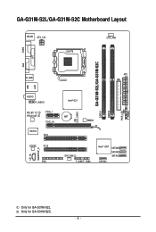
Only for GA-G31M-S2L. CI CLR_CMOS GA-G31M-S2L/GA-G31M-S2C DDRII1 DDRII2 PWR_LED F_PANEL GA-G31M-S2L/GA-G31M-S2C Motherboard Layout KB_MS ATX_12V LGA775 CPU_FAN COMA LPT LAN VGA R_USB ATX IDE USB AUDIO F_AUDIO RTL8111C RTL8102E PCIE_1 PCIE_16 IT8718 PCI1 CODEC PCI2 CD_IN SPDIF_O FDD Intel® G31 BAT MBIOS SYS_FAN F_USB1F_USB2 Intel® ICH7 SATAII3 SATAII2 SATAII1 SATAII0 Only for GA-G31M-S2C. - 8 -
Only for GA-G31M-S2L. CI CLR_CMOS GA-G31M-S2L/GA-G31M-S2C DDRII1 DDRII2 PWR_LED F_PANEL GA-G31M-S2L/GA-G31M-S2C Motherboard Layout KB_MS ATX_12V LGA775 CPU_FAN COMA LPT LAN VGA R_USB ATX IDE USB AUDIO F_AUDIO RTL8111C RTL8102E PCIE_1 PCIE_16 IT8718 PCI1 CODEC PCI2 CD_IN SPDIF_O FDD Intel® G31 BAT MBIOS SYS_FAN F_USB1F_USB2 Intel® ICH7 SATAII3 SATAII2 SATAII1 SATAII0 Only for GA-G31M-S2C. - 8 -
Manual
Page 12
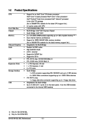
GA-G31M-S2L/S2C Motherboard - 12 - 1-2 Product Specifications CPU Front Side Bus Chipset Memory Onboard Graphics Audio LAN Expansion Slots Storage Interface USB Š Support for an Intel® CoreTM 2 Extreme processor/ Intel® CoreTM 2 Quad processor/Intel® CoreTM...Dual channel memory architecture Š Support for DDR2 800/667 MHz memory modules (Go to GIGABYTE's website for the latest memory support list.) Š Integrated in the North Bridge Š Realtek ALC662 codec Š High Definition Audio Š 2/4/5.1-channel Š Support for S/PDIF Out Š Support for CD In ...
GA-G31M-S2L/S2C Motherboard - 12 - 1-2 Product Specifications CPU Front Side Bus Chipset Memory Onboard Graphics Audio LAN Expansion Slots Storage Interface USB Š Support for an Intel® CoreTM 2 Extreme processor/ Intel® CoreTM 2 Quad processor/Intel® CoreTM...Dual channel memory architecture Š Support for DDR2 800/667 MHz memory modules (Go to GIGABYTE's website for the latest memory support list.) Š Integrated in the North Bridge Š Realtek ALC662 codec Š High Definition Audio Š 2/4/5.1-channel Š Support for S/PDIF Out Š Support for CD In ...

Manual
Page 13
...138; 4 x SATA 3Gb/s connectors Š 1 x CPU fan header Š 1 x system fan header Š 1 x front panel header Š 1 x front panel audio header Š 1 x CD In connector Š 1 x S/PDIF Out header Š 2 x USB 2.0/1.1 headers Š 1 x chassis intrusion header Š 1 x power...Š 1 x serial port Š 1 x D-Sub port Š 4 x USB 2.0/1.1 ports Š 1 x RJ-45 port Š 3 x audio jacks (Line In/Line Out/Microphone) I/O Controller Š iTE IT8718 chip Hardware Monitor Š System voltage detection Š CPU temperature detection Š CPU/System fan...
...138; 4 x SATA 3Gb/s connectors Š 1 x CPU fan header Š 1 x system fan header Š 1 x front panel header Š 1 x front panel audio header Š 1 x CD In connector Š 1 x S/PDIF Out header Š 2 x USB 2.0/1.1 headers Š 1 x chassis intrusion header Š 1 x power...Š 1 x serial port Š 1 x D-Sub port Š 4 x USB 2.0/1.1 ports Š 1 x RJ-45 port Š 3 x audio jacks (Line In/Line Out/Microphone) I/O Controller Š iTE IT8718 chip Hardware Monitor Š System voltage detection Š CPU temperature detection Š CPU/System fan...
Manual
Page 22
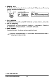
.... Refer to the instructions on setting up to this jack. Line Out Jack (Green) The default line out jack. Use this audio jack for GA-G31M-S2C. GA-G31M-S2L/S2C Motherboard - 22 - This jack can be connected to 100 Mbps data rate. Connection/ Speed LED Activity LED Connection/Speed LED: State Description Green 100 ... an optical drive, walkman, etc. Only for line in jack. RJ-45 LAN Port The Fast Ethernet LAN port provides Internet connection at up a 2/4/5.1-channel audio configuration in jack. The following describes the states of the LAN port LEDs.
.... Refer to the instructions on setting up to this jack. Line Out Jack (Green) The default line out jack. Use this audio jack for GA-G31M-S2C. GA-G31M-S2L/S2C Motherboard - 22 - This jack can be connected to 100 Mbps data rate. Connection/ Speed LED Activity LED Connection/Speed LED: State Description Green 100 ... an optical drive, walkman, etc. Only for line in jack. RJ-45 LAN Port The Fast Ethernet LAN port provides Internet connection at up a 2/4/5.1-channel audio configuration in jack. The following describes the states of the LAN port LEDs.

Manual
Page 29
... connection between the module connector and the motherboard header will be present on each wire instead of a single plug. For HD Front Panel Audio: For AC'97 Front Panel Audio: 2 10 Pin No. 1 Definition MIC2_L Pin No. 1 Definition MIC 2 1 9 3 GND MIC2_R 2 GND 3 MIC Power 4 -ACZ_DET...NC 7 GND 7 NC 8 No Pin 8 No Pin 9 LINE2_L 9 Line Out (L) 10 FAUDIO_JD 10 NC • The front panel audio header supports HD audio by default. Hardware Installation Make sure the wire assignments of the module connector match the pin assignments of the front and back panel...
... connection between the module connector and the motherboard header will be present on each wire instead of a single plug. For HD Front Panel Audio: For AC'97 Front Panel Audio: 2 10 Pin No. 1 Definition MIC2_L Pin No. 1 Definition MIC 2 1 9 3 GND MIC2_R 2 GND 3 MIC Power 4 -ACZ_DET...NC 7 GND 7 NC 8 No Pin 8 No Pin 9 LINE2_L 9 Line Out (L) 10 FAUDIO_JD 10 NC • The front panel audio header supports HD audio by default. Hardware Installation Make sure the wire assignments of the module connector match the pin assignments of the front and back panel...
Manual
Page 30
... computer and unplug the power cord from the power outlet to prevent damage to an audio device that supports digital audio in damage to the device. 14) F_USB1/F_USB2 (USB Headers) The headers conform to USB 2.0/1.1 specification. GA-G31M-S2L/S2C Motherboard - 30 - Each USB header can connect to the USB bracket. Pin No. Incorrect...
... computer and unplug the power cord from the power outlet to prevent damage to an audio device that supports digital audio in damage to the device. 14) F_USB1/F_USB2 (USB Headers) The headers conform to USB 2.0/1.1 specification. GA-G31M-S2L/S2C Motherboard - 30 - Each USB header can connect to the USB bracket. Pin No. Incorrect...
Manual
Page 36
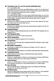
It allows you to restrict access to the system and BIOS Setup. It allows you can also carry out this task.) GA-G31M-S2L/S2C Motherboard - 36 - Pressing to the confirmation message will exit BIOS Setup. (Pressing can use the SPACE key) and then press to a profile. &#...the CPU, and the primary display adapter. „ Integrated Peripherals Use this menu to configure all peripheral devices, such as IDE, SATA, USB, integrated audio, and integrated LAN, etc. „ Power Management Setup Use this menu to configure all the power-saving functions. „ PnP/PCI Configurations Use ...
It allows you to restrict access to the system and BIOS Setup. It allows you can also carry out this task.) GA-G31M-S2L/S2C Motherboard - 36 - Pressing to the confirmation message will exit BIOS Setup. (Pressing can use the SPACE key) and then press to a profile. &#...the CPU, and the primary display adapter. „ Integrated Peripherals Use this menu to configure all peripheral devices, such as IDE, SATA, USB, integrated audio, and integrated LAN, etc. „ Power Management Setup Use this menu to configure all the power-saving functions. „ PnP/PCI Configurations Use ...
Manual
Page 43
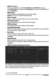
... Mouse Support Allows USB mouse to be automatically set to Ch. 1 Master/Slave. Refer to the following information for diagnosing your LAN cable: Only for GA-G31M-S2L. - 43 - Pair1-2 Status = Open Pair3-6 Status = Open Pair4-5 Status = Open Pair7-8 Status = Open / Length = 0m / Length = 0m / Length = 0m / Length...USB storage devices, including USB flash drives and USB hard drives during the POST. (Default: Enabled) Azalia Codec Enables or disables the onboard audio function. (Default: Auto) If you wish to install a 3rd party add-in network card instead of using the onboard LAN, set ...
... Mouse Support Allows USB mouse to be automatically set to Ch. 1 Master/Slave. Refer to the following information for diagnosing your LAN cable: Only for GA-G31M-S2L. - 43 - Pair1-2 Status = Open Pair3-6 Status = Open Pair4-5 Status = Open Pair7-8 Status = Open / Length = 0m / Length = 0m / Length = 0m / Length...USB storage devices, including USB flash drives and USB hard drives during the POST. (Default: Enabled) Azalia Codec Enables or disables the onboard audio function. (Default: Auto) If you wish to install a 3rd party add-in network card instead of using the onboard LAN, set ...

Manual
Page 71
... icon to the right shows the default audio jack assignments. Line In Front Speaker Out Mic In Audio signals will appear in and out) to instructions on the back panel which support 2/4/5.1-channel(Note) audio. High Definition Audio (HD Audio) HD Audio includes multiple high quality digital-to the ...following instructions use Windows XP as the example operating system.) Step 1: After installing the audio driver, the Audio Manager icon will be simultaneously processed. For example, users can listen to MP3 music, have an Internet chat, make...
... icon to the right shows the default audio jack assignments. Line In Front Speaker Out Mic In Audio signals will appear in and out) to instructions on the back panel which support 2/4/5.1-channel(Note) audio. High Definition Audio (HD Audio) HD Audio includes multiple high quality digital-to the ...following instructions use Windows XP as the example operating system.) Step 1: After installing the audio driver, the Audio Manager icon will be simultaneously processed. For example, users can listen to MP3 music, have an Internet chat, make...

Manual
Page 72
... of device you wish to complete the configuration. Select the device according to an audio jack, the Connected device box appears. Front Speaker Out Rear Speaker Out Center/Subwoofer Speaker Out GA-G31M-S2L/S2C Motherboard - 72 - Step 2: Click the Audio I/O tab. Step 3: The pictures to the right show the 2-, 4-, 5.1-channel speaker configurations. 2-Channel Speakers...
... of device you wish to complete the configuration. Select the device according to an audio jack, the Connected device box appears. Front Speaker Out Rear Speaker Out Center/Subwoofer Speaker Out GA-G31M-S2L/S2C Motherboard - 72 - Step 2: Click the Audio I/O tab. Step 3: The pictures to the right show the 2-, 4-, 5.1-channel speaker configurations. 2-Channel Speakers...

Manual
Page 73
Configuring Sound Effect: You may configure an audio environment on the Audio I /O tab. Muting the Back Panel Audio (For HD Audio Only): Click the tool icon on the Audio I /O tab. Click OK to complete. Click OK to complete. - 73 - On the Connector Settings box, select the Mute rear panel... On the Connector Settings box, select the Disable front panel jack detection check box. D. Activating an AC'97 Front Panel Audio Module: If your chassis provides an AC'97 front panel audio module, to activate the AC'97 functionality, click the tool icon on the Sound Effect tab. Appendix
Configuring Sound Effect: You may configure an audio environment on the Audio I /O tab. Muting the Back Panel Audio (For HD Audio Only): Click the tool icon on the Audio I /O tab. Click OK to complete. Click OK to complete. - 73 - On the Connector Settings box, select the Mute rear panel... On the Connector Settings box, select the Disable front panel jack detection check box. D. Activating an AC'97 Front Panel Audio Module: If your chassis provides an AC'97 front panel audio module, to activate the AC'97 functionality, click the tool icon on the Sound Effect tab. Appendix

Manual
Page 74
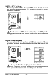
... the metal bracket to the chassis back panel with pin 1 of the SPDIF_O header. Pin 1 (the red wire) of the cable to get the best audio quality. GA-G31M-S2L/S2C Motherboard - 74 - Install the S/PDIF in damage to an external decoder. A. Installing the S/PDIF Out Cable: Step 1: First, attach the connector at the...
... the metal bracket to the chassis back panel with pin 1 of the SPDIF_O header. Pin 1 (the red wire) of the cable to get the best audio quality. GA-G31M-S2L/S2C Motherboard - 74 - Install the S/PDIF in damage to an external decoder. A. Installing the S/PDIF Out Cable: Step 1: First, attach the connector at the...

Manual
Page 75
Configuring S/PDIF out: Click the tool icon in the DIGITAL section. Appendix In the S/PDIF Settings dialog box, select an output sampling rate and select (or disable) the output source. Click OK to an external decoder for transmitting the S/PDIF digital audio signals. S/PDIF Coaxial Cable Step 3: Connect a S/PDIF coaxial cable or a S/PDIF optical cable (either one) to complete the configuration. (Note) The actual locations of the SPDIF In and SPDIF Out connectors may differ by model. - 75 - S/PDIF Optical Cable B.
Configuring S/PDIF out: Click the tool icon in the DIGITAL section. Appendix In the S/PDIF Settings dialog box, select an output sampling rate and select (or disable) the output source. Click OK to an external decoder for transmitting the S/PDIF digital audio signals. S/PDIF Coaxial Cable Step 3: Connect a S/PDIF coaxial cable or a S/PDIF optical cable (either one) to complete the configuration. (Note) The actual locations of the SPDIF In and SPDIF Out connectors may differ by model. - 75 - S/PDIF Optical Cable B.
Manual
Page 76
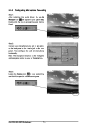
...on the front panel. Step 2: Connect your system tray and click it to open the volume control panel GA-G31M-S2L/S2C Motherboard - 76 - Step 3: Locate the Volume icon in your microphone to access the Audio Control Panel. Double-click the icon to the Mic in jack (pink) on the back panel or ...the Line in your system tray. 5-1-3 Configuring Microphone Recording Step 1: After installing the audio driver, the Audio Manager icon will appear in jack on the front panel and back panel cannot be used at the same time. Then configure the jack...
...on the front panel. Step 2: Connect your system tray and click it to open the volume control panel GA-G31M-S2L/S2C Motherboard - 76 - Step 3: Locate the Volume icon in your microphone to access the Audio Control Panel. Double-click the icon to the Mic in jack (pink) on the back panel or ...the Line in your system tray. 5-1-3 Configuring Microphone Recording Step 1: After installing the audio driver, the Audio Manager icon will appear in jack on the front panel and back panel cannot be used at the same time. Then configure the jack...

Manual
Page 77
...wish to show and click OK to set the volume at a middle level. In the Mixer device list, select Realtek HD Audio Input. Select Realtek HD Audio Input in Master Volume, go to Options and click Properties. Do NOT mute the recording sound, or you will not hear ... when playing back the recording you set the recording sound for your recording device(s) altogether. ing process when using the microphone function on the audio specifications, to adjust the recording sound, use the Recording option to complete. Appendix It is recommended that you just made. (Note) Based ...
...wish to show and click OK to set the volume at a middle level. In the Mixer device list, select Realtek HD Audio Input. Select Realtek HD Audio Input in Master Volume, go to Options and click Properties. Do NOT mute the recording sound, or you will not hear ... when playing back the recording you set the recording sound for your recording device(s) altogether. ing process when using the microphone function on the audio specifications, to adjust the recording sound, use the Recording option to complete. Appendix It is recommended that you just made. (Note) Based ...

Manual
Page 78
... Advanced button under a volume control option (e.g. To stop playing, click the Stop button . 5. To play . 3. Playing the Sound: 1. Front Green In, Front Pink In). ton . 4. GA-G31M-S2L/S2C Motherboard - 78 - To record a sound file, click the Recording but- In the Open dialog box, select the sound (.wav) file you have connected the...
... Advanced button under a volume control option (e.g. To stop playing, click the Stop button . 5. To play . 3. Playing the Sound: 1. Front Green In, Front Pink In). ton . 4. GA-G31M-S2L/S2C Motherboard - 78 - To record a sound file, click the Recording but- In the Open dialog box, select the sound (.wav) file you have connected the...


