Manual
Page 1
GA-G31M-ES2L/ GA-G31M-ES2C LGA775 socket motherboard for Intel® CoreTM processor family/ Intel® Pentium® processor family/Intel® Celeron® processor family User's Manual Rev. 2301 12ME-G31MES2L-2301R
GA-G31M-ES2L/ GA-G31M-ES2C LGA775 socket motherboard for Intel® CoreTM processor family/ Intel® Pentium® processor family/Intel® Celeron® processor family User's Manual Rev. 2301 12ME-G31MES2L-2301R

Manual
Page 3
... of documentations: For detailed product information, carefully read the User's Manual. For instructions on how to use GIGABYTE's unique features, read or download the information on/from the Support&Downloads\Motherboard\Technology Guide page on your motherboard revision before updating motherboard BIOS, drivers, or when looking for technical information. The trademarks mentioned in...
... of documentations: For detailed product information, carefully read the User's Manual. For instructions on how to use GIGABYTE's unique features, read or download the information on/from the Support&Downloads\Motherboard\Technology Guide page on your motherboard revision before updating motherboard BIOS, drivers, or when looking for technical information. The trademarks mentioned in...
Manual
Page 6
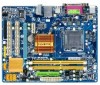
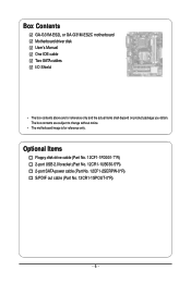
Optional Items Floppy disk drive cable (Part No. 12CF1-1FD001-7*R) 2-port USB 2.0 bracket (Part No. 12CR1-1UB030-5*R) 2-port SATA power cable (Part No. 12CF1-2SERPW-0*R) S/PDIF out cable (Part No. 12CR1-1SPOUT-0*R) - 6 - The box contents are for reference only. Box Contents GA-G31M-ES2L or GA-G31M-ES2C motherboard Motherboard driver disk User's Manual One IDE cable Two SATA cables I/O Shield • The box contents above are subject to change without notice. • The motherboard image is for reference only and the actual items shall depend on product package you obtain.
Optional Items Floppy disk drive cable (Part No. 12CF1-1FD001-7*R) 2-port USB 2.0 bracket (Part No. 12CR1-1UB030-5*R) 2-port SATA power cable (Part No. 12CF1-2SERPW-0*R) S/PDIF out cable (Part No. 12CR1-1SPOUT-0*R) - 6 - The box contents are for reference only. Box Contents GA-G31M-ES2L or GA-G31M-ES2C motherboard Motherboard driver disk User's Manual One IDE cable Two SATA cables I/O Shield • The box contents above are subject to change without notice. • The motherboard image is for reference only and the actual items shall depend on product package you obtain.
Manual
Page 9
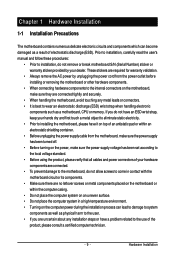
... that all cables and power connectors of your dealer. If you are connected tightly and securely. • When handling the motherboard, avoid touching any installation steps or have a problem related to wear an electrostatic discharge (ESD) wrist strap when handling electronic... product, please consult a certified computer technician. - 9 - Prior to installation, carefully read the user's manual and follow these procedures: • Prior to installation, do not remove or break motherboard S/N (Serial Number) sticker or warranty sticker provided by unplugging the power cord from the...
... that all cables and power connectors of your dealer. If you are connected tightly and securely. • When handling the motherboard, avoid touching any installation steps or have a problem related to wear an electrostatic discharge (ESD) wrist strap when handling electronic... product, please consult a certified computer technician. - 9 - Prior to installation, carefully read the user's manual and follow these procedures: • Prior to installation, do not remove or break motherboard S/N (Serial Number) sticker or warranty sticker provided by unplugging the power cord from the...
Manual
Page 15
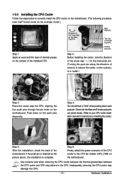
...6: Finally, attach the power connector of the CPU cooler to your CPU cooler installation manual for instructions on installing the cooler.) Step 5: After the installation, check the back of the motherboard. Hardware Installation Inadequately removing the CPU cooler may adhere to correctly install the CPU cooler...four push pins through the pin holes on the push pins diagonally. Step 4: You should hear a "click" when pushing down on the motherboard. Use extreme care when removing the CPU cooler because the thermal grease/tape between the CPU cooler and CPU may damage the CPU. - 15...
...6: Finally, attach the power connector of the CPU cooler to your CPU cooler installation manual for instructions on installing the cooler.) Step 5: After the installation, check the back of the motherboard. Hardware Installation Inadequately removing the CPU cooler may adhere to correctly install the CPU cooler...four push pins through the pin holes on the push pins diagonally. Step 4: You should hear a "click" when pushing down on the motherboard. Use extreme care when removing the CPU cooler because the thermal grease/tape between the CPU cooler and CPU may damage the CPU. - 15...
Manual
Page 18
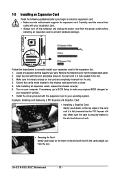
...8226; Removing the Card: Gently push back on the lever on the top edge of the card until it is fully inserted into the slot. 4. GA-G31M-ES2L/ES2C Motherboard - 18 - Make sure the card is securely seated in the slot. 3. Locate an expansion slot that came with your computer. Align the card ...with the slot, and press down on the slot and then lift the card straight out from the chassis back panel. 2. Carefully read the manual that...
...8226; Removing the Card: Gently push back on the lever on the top edge of the card until it is fully inserted into the slot. 4. GA-G31M-ES2L/ES2C Motherboard - 18 - Make sure the card is securely seated in the slot. 3. Locate an expansion slot that came with your computer. Align the card ...with the slot, and press down on the slot and then lift the card straight out from the chassis back panel. 2. Carefully read the manual that...
Manual
Page 29
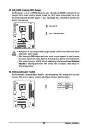
... the jumper. Pin No. Hardware Installation Failure to do so may cause damage to the motherboard. • After system restart, go to BIOS Setup to load factory defaults (select Load Optimized Defaults) or manually configure the BIOS settings (refer to clear the CMOS values (e.g. Definition 1 Signal 1 2...and reset the CMOS values to touch the two pins for BIOS configurations). 16) CI (Chassis Intrusion Header) This motherboard provides a chassis detection feature that detects if the chassis cover has been removed. This function requires a chassis with chassis intrusion detection design...
... the jumper. Pin No. Hardware Installation Failure to do so may cause damage to the motherboard. • After system restart, go to BIOS Setup to load factory defaults (select Load Optimized Defaults) or manually configure the BIOS settings (refer to clear the CMOS values (e.g. Definition 1 Signal 1 2...and reset the CMOS values to touch the two pins for BIOS configurations). 16) CI (Chassis Intrusion Header) This motherboard provides a chassis detection feature that detects if the chassis cover has been removed. This function requires a chassis with chassis intrusion detection design...
Manual
Page 36
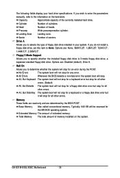
... called conventional memory. If you to the information on the system. Floppy 3 Mode Support Allows you wish to enter the parameters manually, refer to specify whether the installed floppy disk drive is 3-mode floppy disk drive, a Japanese standard floppy disk drive. Halt ...for any error. Head Number of sectors. All Errors Whenever the BIOS detects a non-fatal error the system boot will not stop . GA-G31M-ES2L/ES2C Motherboard - 36 - Memory These fields are read-only and are : Disabled (default), Drive A. Cylinder Number of extended memory. Landing Zone ...
... called conventional memory. If you to the information on the system. Floppy 3 Mode Support Allows you wish to enter the parameters manually, refer to specify whether the installed floppy disk drive is 3-mode floppy disk drive, a Japanese standard floppy disk drive. Halt ...for any error. Head Number of sectors. All Errors Whenever the BIOS detects a non-fatal error the system boot will not stop . GA-G31M-ES2L/ES2C Motherboard - 36 - Memory These fields are read-only and are : Disabled (default), Drive A. Cylinder Number of extended memory. Landing Zone ...
Manual
Page 40
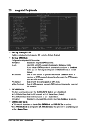
... SATA Port 0/2 Set to Ch. 0 Master/Slave. If your onboard SATA controller is automatically configured to Combined mode, you can manually re-configure it to Enhanced mode as needed. (Default) Combined Sets all SATA devices to operate in PATA mode and disables the ...(Default: Enabled) On-Chip SATA Mode Configures the integrated SATA controller. When PATA IDE Set to is set to Combined or Enhanced mode. GA-G31M-ES2L/ES2C Motherboard - 40 - Combined allows a maximum of 4 ATA devices to be automatically set SATA devices to Combined. Non-Combined Sets all SATA devices...
... SATA Port 0/2 Set to Ch. 0 Master/Slave. If your onboard SATA controller is automatically configured to Combined mode, you can manually re-configure it to Enhanced mode as needed. (Default) Combined Sets all SATA devices to operate in PATA mode and disables the ...(Default: Enabled) On-Chip SATA Mode Configures the integrated SATA controller. When PATA IDE Set to is set to Combined or Enhanced mode. GA-G31M-ES2L/ES2C Motherboard - 40 - Combined allows a maximum of 4 ATA devices to be automatically set SATA devices to Combined. Non-Combined Sets all SATA devices...
Manual
Page 48
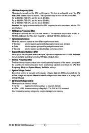
... to set in damage to operate at 0.1V increment. GA-G31M-ES2L/ES2C Motherboard - 48 - Options are dependent on CPU FSB. the second is the memory frequency that is highly recommended that the CPU frequency be configurable. (Default: Manual) DDR2 OverVoltage Control Allows you to manually set this item to be set memory voltage. For an...
... to set in damage to operate at 0.1V increment. GA-G31M-ES2L/ES2C Motherboard - 48 - Options are dependent on CPU FSB. the second is the memory frequency that is highly recommended that the CPU frequency be configurable. (Default: Manual) DDR2 OverVoltage Control Allows you to manually set this item to be set memory voltage. For an...
Manual
Page 53
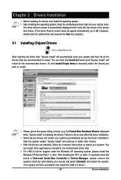
... 3 Drivers Installation • Before installing the drivers, first install the operating system. • After installing the operating system, insert the motherboard driver disk into your mouse and select Uninstall) and restart the system. (The system will then autodetect and install the USB 2.0 driver.)... under the Windows XP operating system, please install the Windows XP Service Pack 1 or later. Or click Install Single Items to manually select the drivers you wish to install. Drivers Installation You can install other drivers. • After the drivers are recommended to ...
... 3 Drivers Installation • Before installing the drivers, first install the operating system. • After installing the operating system, insert the motherboard driver disk into your mouse and select Uninstall) and restart the system. (The system will then autodetect and install the USB 2.0 driver.)... under the Windows XP operating system, please install the Windows XP Service Pack 1 or later. Or click Install Single Items to manually select the drivers you wish to install. Drivers Installation You can install other drivers. • After the drivers are recommended to ...
Manual
Page 54
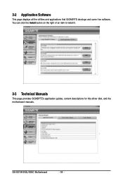
You can click the Install button on the right of an item to install it. 3-3 Technical Manuals This page provides GIGABYTE's application guides, content descriptions for this driver disk, and the motherboard manuals. GA-G31M-ES2L/ES2C Motherboard - 54 - 3-2 Application Software This page displays all the utilities and applications that GIGABYTE develops and some free software.
You can click the Install button on the right of an item to install it. 3-3 Technical Manuals This page provides GIGABYTE's application guides, content descriptions for this driver disk, and the motherboard manuals. GA-G31M-ES2L/ES2C Motherboard - 54 - 3-2 Application Software This page displays all the utilities and applications that GIGABYTE develops and some free software.
Manual
Page 60
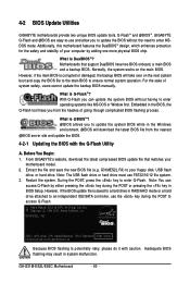
...system boot and copy the BIOS file to the main BIOS to enter operating systems like MS-DOS or Window first. GA-G31M-ES2L/ES2C Motherboard - 60 - Motherboards that matches your floppy disk, USB flash drive, or hard drive. What is corrupted or damaged, the backup BIOS ... and @BIOSTM. What is Q-FlashTM? Restart the system. Additionally, this motherboard features the DualBIOSTM design, which enhances protection for the safety and stability of system safety, users cannot update the backup BIOS manually. GIGABYTE Q-Flash and @BIOS are easy-to update the system BIOS while in ...
...system boot and copy the BIOS file to the main BIOS to enter operating systems like MS-DOS or Window first. GA-G31M-ES2L/ES2C Motherboard - 60 - Motherboards that matches your floppy disk, USB flash drive, or hard drive. What is corrupted or damaged, the backup BIOS ... and @BIOSTM. What is Q-FlashTM? Restart the system. Additionally, this motherboard features the DualBIOSTM design, which enhances protection for the safety and stability of system safety, users cannot update the backup BIOS manually. GIGABYTE Q-Flash and @BIOS are easy-to update the system BIOS while in ...
Manual
Page 63
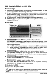
... BIOS update file obtained from the Internet or through other source. C. After Updating the BIOS: Restart your motherboard is not present on the @BIOS server site, please manually download the BIOS update file from GIGABYTE Server, select the @BIOS server site closest to your location and then download the BIOS file that matches...
... BIOS update file obtained from the Internet or through other source. C. After Updating the BIOS: Restart your motherboard is not present on the @BIOS server site, please manually download the BIOS update file from GIGABYTE Server, select the @BIOS server site closest to your location and then download the BIOS file that matches...
Manual
Page 69
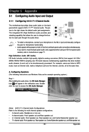
... over the Internet, and etc. Line In Front Speaker Out Mic In • To install a microphone, connect your microphone to the Mic in jack and manually configure the jack for microphone functionality. • Audio signals will appear in and out) to instructions on the back panel which support 2/4/5.1/7.1(Note)-channel audio... installing the audio driver, the HD Audio Manager icon will be simultaneously processed. Appendix Chapter 5 Appendix 5-1 Configuring Audio Input and Output 5-1-1 Configuring 2/4/5.1/7.1-Channel Audio The motherboard provides three audio jacks on page 71.
... over the Internet, and etc. Line In Front Speaker Out Mic In • To install a microphone, connect your microphone to the Mic in jack and manually configure the jack for microphone functionality. • Audio signals will appear in and out) to instructions on the back panel which support 2/4/5.1/7.1(Note)-channel audio... installing the audio driver, the HD Audio Manager icon will be simultaneously processed. Appendix Chapter 5 Appendix 5-1 Configuring Audio Input and Output 5-1-1 Configuring 2/4/5.1/7.1-Channel Audio The motherboard provides three audio jacks on page 71.
Manual
Page 80
...should not be construed as a commitment by GIGABYTE. GA-G31M-ES2L/ES2C Motherboard - 80 - Waste Electrical & Electronic Equipment (WEEE) Directive Statement GIGABYTE will help you may contact us at the Customer Care number listed in your product's user's manual and we at the time of harmful ...this product must not be glad to help to develop products that the information contained herein was accurate in all GIGABYTE motherboards fulfill European Union regulations for RoHS (Restriction of Certain Hazardous Substances in your local or regional waste collection administration ...
...should not be construed as a commitment by GIGABYTE. GA-G31M-ES2L/ES2C Motherboard - 80 - Waste Electrical & Electronic Equipment (WEEE) Directive Statement GIGABYTE will help you may contact us at the Customer Care number listed in your product's user's manual and we at the time of harmful ...this product must not be glad to help to develop products that the information contained herein was accurate in all GIGABYTE motherboards fulfill European Union regulations for RoHS (Restriction of Certain Hazardous Substances in your local or regional waste collection administration ...


