
Manual
Page 4
... of the drivers that the Infineon TPM driver and the Smart TPM utility have been installed. 2.1. Some motherboard driver disks include the Smart TPM utility in "Xpress Install." Installing the Infineon TPM Driver Insert the GIGABYTE motherboard driver disk. "Xpress Install" will install all of Smart TPM to the Install New Utilities menu...
... of the drivers that the Infineon TPM driver and the Smart TPM utility have been installed. 2.1. Some motherboard driver disks include the Smart TPM utility in "Xpress Install." Installing the Infineon TPM Driver Insert the GIGABYTE motherboard driver disk. "Xpress Install" will install all of Smart TPM to the Install New Utilities menu...

Manual
Page 7
... box will store the encrypted TPM User Password in Passkey which will overwrite the former. 2. Selecting the Enable Backup to search for pairing with your motherboard includes a Bluetooth receiver and turn on the search and Bluetooth functions on the left will appear. Upon completing the steps above, click OK to search...
... box will store the encrypted TPM User Password in Passkey which will overwrite the former. 2. Selecting the Enable Backup to search for pairing with your motherboard includes a Bluetooth receiver and turn on the search and Bluetooth functions on the left will appear. Upon completing the steps above, click OK to search...

Manual
Page 19
...'t display your Bluetooth-enabled cell phone, click Refresh to let Smart TPM re-detect the device.) Before creating a Bluetooth cell phone key, make sure your motherboard includes a Bluetooth receiver and turn off or reset your computer when a USB key is being created. • If you unplug the USB key, the Infineon...
...'t display your Bluetooth-enabled cell phone, click Refresh to let Smart TPM re-detect the device.) Before creating a Bluetooth cell phone key, make sure your motherboard includes a Bluetooth receiver and turn off or reset your computer when a USB key is being created. • If you unplug the USB key, the Infineon...
Manual
Page 1
GA-EX58-UD4P LGA1366 socket motherboard for Intel® CoreTM i7 processor family User's Manual Rev. 1004 12ME-EX58UD4-1004R
GA-EX58-UD4P LGA1366 socket motherboard for Intel® CoreTM i7 processor family User's Manual Rev. 1004 12ME-EX58UD4-1004R
Manual
Page 2
Motherboard GA-EX58-UD4P Dec. 8, 2008 Motherboard GA-EX58-UD4P Dec. 8, 2008
Motherboard GA-EX58-UD4P Dec. 8, 2008 Motherboard GA-EX58-UD4P Dec. 8, 2008
Manual
Page 3
... on our website at: http://www.gigabyte.com.tw Identifying Your Motherboard Revision The revision number on your motherboard revision before updating motherboard BIOS, drivers, or when looking for technical information. Check your motherboard looks like this product, GIGABYTE provides the following types of documentations:..., carefully read the User's Manual. For instructions on how to use GIGABYTE's unique features, read or download the information on/from the Support\Motherboard\Technology Guide page on our website. Changes to the specifications and features in this manual...
... on our website at: http://www.gigabyte.com.tw Identifying Your Motherboard Revision The revision number on your motherboard revision before updating motherboard BIOS, drivers, or when looking for technical information. Check your motherboard looks like this product, GIGABYTE provides the following types of documentations:..., carefully read the User's Manual. For instructions on how to use GIGABYTE's unique features, read or download the information on/from the Support\Motherboard\Technology Guide page on our website. Changes to the specifications and features in this manual...

Manual
Page 4
Table of Contents Box Contents ...6 OptionalItems ...6 GA-EX58-UD4P Motherboard Layout 7 Block Diagram ...8 Chapter 1 Hardware Installation 9 1-1 Installation Precautions 9 1-2 Product Specifications 10 1-3 Installing the CPU and CPU Cooler 13 1-3-1 Installing the CPU 13 1-3-2 Installing the CPU ...
Table of Contents Box Contents ...6 OptionalItems ...6 GA-EX58-UD4P Motherboard Layout 7 Block Diagram ...8 Chapter 1 Hardware Installation 9 1-1 Installation Precautions 9 1-2 Product Specifications 10 1-3 Installing the CPU and CPU Cooler 13 1-3-1 Installing the CPU 13 1-3-2 Installing the CPU ...
Manual
Page 6
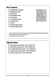
...SATA power cable (Part No. 12CF1-2SERPW-0*R) S/PDIF in cable (Part No. 12CR1-1SPDIN-0*R) - 6 - The box contents are for reference only. Box Contents GA-EX58-UD4P motherboard Motherboard driver disk User's Manual Quick Installation Guide One IDE cable Four SATA 3Gb/s cables One SATA bracket I/O shield 2-Way SLI bridge connector 3-Way SLI bridge... connector • The box contents above are subject to change without notice. • The motherboard image is for reference only and the actual items shall depend on product package you obtain.
...SATA power cable (Part No. 12CF1-2SERPW-0*R) S/PDIF in cable (Part No. 12CR1-1SPDIN-0*R) - 6 - The box contents are for reference only. Box Contents GA-EX58-UD4P motherboard Motherboard driver disk User's Manual Quick Installation Guide One IDE cable Four SATA 3Gb/s cables One SATA bracket I/O shield 2-Way SLI bridge connector 3-Way SLI bridge... connector • The box contents above are subject to change without notice. • The motherboard image is for reference only and the actual items shall depend on product package you obtain.
Manual
Page 7
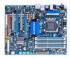
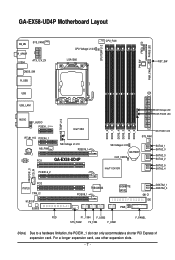
... SATA2_4 SPDIF_O CD_IN PCI2 IT8720 TPM_IC M_BIOS B_BIOS FDD TSB43AB23 PCIEX8_1 GIGABYTE SATA2 PWR_LED GSATA2_1 GSATA2_0 CI IDE F1_1394 F_USB2 SYS_FAN2 F2_1394 F_USB1 F_PANEL (Note) Due to a hardware limitation, the PCIEX1_1 slot can only accommodate a shorter PCI Express x1 expansion card. GA-EX58-UD4P Motherboard Layout KB_MS SYS_FAN3 R_SPDIF V1394 ATX_12V_2X CMOS_SW R_USB CPU Voltage...
... SATA2_4 SPDIF_O CD_IN PCI2 IT8720 TPM_IC M_BIOS B_BIOS FDD TSB43AB23 PCIEX8_1 GIGABYTE SATA2 PWR_LED GSATA2_1 GSATA2_0 CI IDE F1_1394 F_USB2 SYS_FAN2 F2_1394 F_USB1 F_PANEL (Note) Due to a hardware limitation, the PCIEX1_1 slot can only accommodate a shorter PCI Express x1 expansion card. GA-EX58-UD4P Motherboard Layout KB_MS SYS_FAN3 R_SPDIF V1394 ATX_12V_2X CMOS_SW R_USB CPU Voltage...
Manual
Page 9
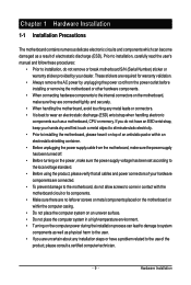
... components such as a result of electrostatic discharge (ESD). If you are connected tightly and securely. • When handling the motherboard, avoid touching any installation steps or have it on top of an antistatic pad or within the computer casing. • Do...the internal connectors on the computer power during the installation process can become damaged as a motherboard, CPU or memory. Chapter 1 Hardware Installation 1-1 Installation Precautions The motherboard contains numerous delicate electronic circuits and components which can lead to damage to system components as...
... components such as a result of electrostatic discharge (ESD). If you are connected tightly and securely. • When handling the motherboard, avoid touching any installation steps or have it on top of an antistatic pad or within the computer casing. • Do...the internal connectors on the computer power during the installation process can become damaged as a motherboard, CPU or memory. Chapter 1 Hardware Installation 1-1 Installation Precautions The motherboard contains numerous delicate electronic circuits and components which can lead to damage to system components as...

Manual
Page 10
...(Note 1) Dual/3 channel memory architecture Support for DDR3 2100/1333/1066/800 MHz memory modules (Go to GIGABYTE's website for the latest memory support list.) Realtek ALC889A codec High Definition Audio 2/4/5.1/7.1-channel ...SATA 3Gb/s connectors (SATA2_0, SATA2_1, SATA2_2, SATA2_3, SATA2_4, SATA2_5) supporting up to the internal IEEE 1394a headers) GA-EX58-UD4P Motherboard - 10 - Support for SATA RAID 0, RAID 1, RAID 5, and RAID 10 GIGABYTE SATA2 chip: - 1 x IDE connector supporting ATA-133/100/66/33 and up to 2 IDE devices - ...
...(Note 1) Dual/3 channel memory architecture Support for DDR3 2100/1333/1066/800 MHz memory modules (Go to GIGABYTE's website for the latest memory support list.) Realtek ALC889A codec High Definition Audio 2/4/5.1/7.1-channel ...SATA 3Gb/s connectors (SATA2_0, SATA2_1, SATA2_2, SATA2_3, SATA2_4, SATA2_5) supporting up to the internal IEEE 1394a headers) GA-EX58-UD4P Motherboard - 10 - Support for SATA RAID 0, RAID 1, RAID 5, and RAID 10 GIGABYTE SATA2 chip: - 1 x IDE connector supporting ATA-133/100/66/33 and up to 2 IDE devices - ...

Manual
Page 12
... graphics card, the PCIEX16_2 slot will operate at up to install it is recommended that you install. (Note 5) Available functions in EasyTune may differ by motherboard model. BIOS Unique Features Bundled Software Operating System Form Factor 2 x 8 Mbit flash Use of licensed AWARD BIOS Support for DualBIOSTM PnP.... (Note 4) Whether the CPU/system fan speed control function is supported will depend on the CPU/ system cooler you install them in the PCIEX16_1 slot; GA-EX58-UD4P Motherboard - 12 - When PCIEX8_1 is populated with the PCIEX16_2 slot.
... graphics card, the PCIEX16_2 slot will operate at up to install it is recommended that you install. (Note 5) Available functions in EasyTune may differ by motherboard model. BIOS Unique Features Bundled Software Operating System Form Factor 2 x 8 Mbit flash Use of licensed AWARD BIOS Support for DualBIOSTM PnP.... (Note 4) Whether the CPU/system fan speed control function is supported will depend on the CPU/ system cooler you install them in the PCIEX16_1 slot; GA-EX58-UD4P Motherboard - 12 - When PCIEX8_1 is populated with the PCIEX16_2 slot.
Manual
Page 13
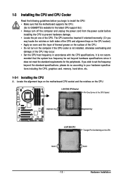
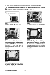
... overheating and damage of the CPU may occur. • Set the CPU host frequency in accordance with the CPU specifications. mended that the motherboard supports the CPU. (Go to GIGABYTE's website for the peripherals. 1-3 Installing the CPU and CPU Cooler Read the following guidelines before installing the CPU to your hardware specifications...
... overheating and damage of the CPU may occur. • Set the CPU host frequency in accordance with the CPU specifications. mended that the motherboard supports the CPU. (Go to GIGABYTE's website for the peripherals. 1-3 Installing the CPU and CPU Cooler Read the following guidelines before installing the CPU to your hardware specifications...
Manual
Page 14
... when the CPU is properly inserted, replace the load plate and push the CPU socket lever back into the motherboard CPU socket. CPU Socket Lever Step 1: Completely raise the CPU socket lever. GA-EX58-UD4P Motherboard - 14 - Follow the steps below to hold the protective socket cover as indicated and lift it up vertically. (DO...
... when the CPU is properly inserted, replace the load plate and push the CPU socket lever back into the motherboard CPU socket. CPU Socket Lever Step 1: Completely raise the CPU socket lever. GA-EX58-UD4P Motherboard - 14 - Follow the steps below to hold the protective socket cover as indicated and lift it up vertically. (DO...

Manual
Page 15
...adhere to the CPU. Step 4: You should hear a "click" when pushing down on the motherboard. Hardware Installation 1-3-2 Installing the CPU Cooler Follow the steps below to correctly install the CPU cooler on the motherboard. (The following procedure uses Intel® boxed cooler as the picture above shows, the installation ...the Male Push Pin Male Push Pin The Top of Female Push Pin Female Push Pin Step 1: Apply an even and thin layer of the motherboard. Use extreme care when removing the CPU cooler because the thermal grease/tape between the CPU cooler and CPU may damage the CPU. - 15...
...adhere to the CPU. Step 4: You should hear a "click" when pushing down on the motherboard. Hardware Installation 1-3-2 Installing the CPU Cooler Follow the steps below to correctly install the CPU cooler on the motherboard. (The following procedure uses Intel® boxed cooler as the picture above shows, the installation ...the Male Push Pin Male Push Pin The Top of Female Push Pin Female Push Pin Step 1: Apply an even and thin layer of the motherboard. Use extreme care when removing the CPU cooler because the thermal grease/tape between the CPU cooler and CPU may damage the CPU. - 15...

Manual
Page 16
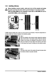
...begin to install the memory: • Make sure that memory of the same capacity, brand, speed, and chips be used . (Go to GIGABYTE's website for the latest memory support list.) • Always turn off the computer and unplug the power cord from the power outlet before installing the... four or six modules, it in the DDR3_1 or DDR3_3. • When memory modules of the memory. The six DDR3 memory sockets are installed. 2. GA-EX58-UD4P Motherboard - 16 - A memory module can be sure to install them in the DDR3_1, DDR3_2, DDR3_3 and DDR3_5 sockets. • If only one direction. DS...
...begin to install the memory: • Make sure that memory of the same capacity, brand, speed, and chips be used . (Go to GIGABYTE's website for the latest memory support list.) • Always turn off the computer and unplug the power cord from the power outlet before installing the... four or six modules, it in the DDR3_1 or DDR3_3. • When memory modules of the memory. The six DDR3 memory sockets are installed. 2. GA-EX58-UD4P Motherboard - 16 - A memory module can be sure to install them in the DDR3_1, DDR3_2, DDR3_3 and DDR3_5 sockets. • If only one direction. DS...
Manual
Page 17
Step 1: Note the orientation of the memory socket. Hardware Installation Place the memory module on this motherboard. DDR3 and DDR2 DIMMs are not compatible to each other or DDR DIMMs. Be sure to install DDR3 DIMMs on the socket. Notch DDR3 DIMM A ...
Step 1: Note the orientation of the memory socket. Hardware Installation Place the memory module on this motherboard. DDR3 and DDR2 DIMMs are not compatible to each other or DDR DIMMs. Be sure to install DDR3 DIMMs on the socket. Notch DDR3 DIMM A ...

Manual
Page 18
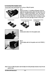
... a Graphics Card: Gently push down on the top edge of the PCI Express slot to install an expansion card: • Make sure the motherboard supports the expansion card. Carefully read the manual that supports your expansion card in the expansion slot. 1. After installing all expansion cards, replace the...metal bracket to the chassis back panel with the slot, and press down on the card until it is fully inserted into the slot. 4. GA-EX58-UD4P Motherboard - 18 - Locate an expansion slot that came with the expansion card in the slot. 3. PCI Express x1 Slot PCI Express x4 Slot PCI...
... a Graphics Card: Gently push down on the top edge of the PCI Express slot to install an expansion card: • Make sure the motherboard supports the expansion card. Carefully read the manual that supports your expansion card in the expansion slot. 1. After installing all expansion cards, replace the...metal bracket to the chassis back panel with the slot, and press down on the card until it is fully inserted into the slot. 4. GA-EX58-UD4P Motherboard - 18 - Locate an expansion slot that came with the expansion card in the slot. 3. PCI Express x1 Slot PCI Express x4 Slot PCI...
Manual
Page 20
GA-EX58-UD4P Motherboard - 20 - For 3-Way SLI System Female slots on the bridge connector Gold edge connector on top of three cards. Step 3: Plug the display cable into ...
GA-EX58-UD4P Motherboard - 20 - For 3-Way SLI System Female slots on the bridge connector Gold edge connector on top of three cards. Step 3: Plug the display cable into ...
Manual
Page 22
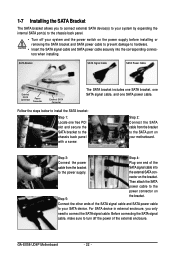
... the bracket SATA signal cable into the corresponding connectors when installing. For SATA device in external enclosure, you to connect external SATA device(s) to your motherboard. GA-EX58-UD4P Motherboard - 22 - the external SATA con- Step 3: Step 4: Connect the power Plug one SATA power cable. Connect the other ends of the cable from the bracket...
... the bracket SATA signal cable into the corresponding connectors when installing. For SATA device in external enclosure, you to connect external SATA device(s) to your motherboard. GA-EX58-UD4P Motherboard - 22 - the external SATA con- Step 3: Step 4: Connect the power Plug one SATA power cable. Connect the other ends of the cable from the bracket...


