Manual
Page 4
Table of Contents Box Contents...6 Optional Items...6 GA-EX58-UD3R Motherboard Layout 7 Block Diagram...8 Chapter 1 Hardware Installation 9 1-1 Installation Precautions 9 1-2 Product Specifications 10 1-3 Installing the CPU and CPU Cooler 13 1-3-1 Installing the CPU 13 1-3-2 Installing the CPU Cooler 15 1-4 Installing the Memory 16 1-4-1 Dual/3 Channel Memory Configuration 16 1-4-2 Installing a Memory 17 1-5 Installing an Expansion Card 18 1-6 Setup of...
Table of Contents Box Contents...6 Optional Items...6 GA-EX58-UD3R Motherboard Layout 7 Block Diagram...8 Chapter 1 Hardware Installation 9 1-1 Installation Precautions 9 1-2 Product Specifications 10 1-3 Installing the CPU and CPU Cooler 13 1-3-1 Installing the CPU 13 1-3-2 Installing the CPU Cooler 15 1-4 Installing the Memory 16 1-4-1 Dual/3 Channel Memory Configuration 16 1-4-2 Installing a Memory 17 1-5 Installing an Expansion Card 18 1-6 Setup of...
Manual
Page 8
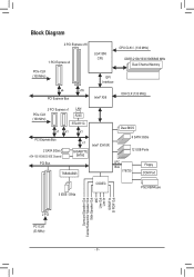
... Express x4 PCIe CLK (100 MHz) x4 x16 PCI Express Bus LGA1366 CPU CPU CLK+/- (133 MHz) DDR3 2100/1333/1066/800 MHz Dual Channel Memory QPI Interface Intel® X58 IOH CLK (133 MHz) 2 PCI Express x1 LAN PCIe CLK RJ45 (100 MHz) RTL8111C x1 x1 x1 PCI Express Bus... x1 2 SATA 3Gb/s ATA-133/100/66/33 IDE Channel PCI Bus GIGABYTE SATA2 TSB43AB23 Intel® ICH10R Dual BIOS 6 SATA 3Gb/s 12 USB Ports LPC Bus IT8720 Floppy COM Port 3 IEEE 1394a CODEC PS/2 KB/Mouse Surround...
... Express x4 PCIe CLK (100 MHz) x4 x16 PCI Express Bus LGA1366 CPU CPU CLK+/- (133 MHz) DDR3 2100/1333/1066/800 MHz Dual Channel Memory QPI Interface Intel® X58 IOH CLK (133 MHz) 2 PCI Express x1 LAN PCIe CLK RJ45 (100 MHz) RTL8111C x1 x1 x1 PCI Express Bus... x1 2 SATA 3Gb/s ATA-133/100/66/33 IDE Channel PCI Bus GIGABYTE SATA2 TSB43AB23 Intel® ICH10R Dual BIOS 6 SATA 3Gb/s 12 USB Ports LPC Bus IT8720 Floppy COM Port 3 IEEE 1394a CODEC PS/2 KB/Mouse Surround...
Manual
Page 9
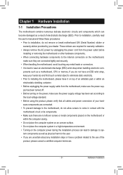
... allow screws to come in a high-temperature environment. • Turning on the computer power during the installation process can become damaged as a motherboard, CPU or memory. Hardware Installation If you are no leftover screws or metal components placed on the motherboard or within an electrostatic shielding container. • Before unplugging the...
... allow screws to come in a high-temperature environment. • Turning on the computer power during the installation process can become damaged as a motherboard, CPU or memory. Hardware Installation If you are no leftover screws or metal components placed on the motherboard or within an electrostatic shielding container. • Before unplugging the...
Manual
Page 10
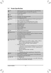
... up to 1 floppy disk drive USB Integrated in the LGA1366 package (Go to GIGABYTE's website for the latest CPU support list.) L3 cache varies with CPU QPI Chipset Memory Audio 4.8GT/s, 6.4GT/s North Bridge: Intel® X58 Express Chipset...4 x 1.5V DDR3 DIMM sockets supporting up to 16 GB of system memory (Note 1) Dual/3 channel memory architecture Support for DDR3 2100/1333/1066/800 MHz memory modules (Go to GIGABYTE's website for the latest memory support list.) Realtek ALC888 codec High Definition Audio &#...
... up to 1 floppy disk drive USB Integrated in the LGA1366 package (Go to GIGABYTE's website for the latest CPU support list.) L3 cache varies with CPU QPI Chipset Memory Audio 4.8GT/s, 6.4GT/s North Bridge: Intel® X58 Express Chipset...4 x 1.5V DDR3 DIMM sockets supporting up to 16 GB of system memory (Note 1) Dual/3 channel memory architecture Support for DDR3 2100/1333/1066/800 MHz memory modules (Go to GIGABYTE's website for the latest memory support list.) Realtek ALC888 codec High Definition Audio &#...
Manual
Page 12
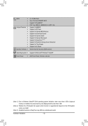
... Form Factor; 30.5cm x 24.4cm (Note 1) Due to Windows Vista/XP 32-bit operating system limitation, when more than 4 GB of physical memory is installed, the actual memory size displayed will be less than 4 GB. (Note 2) Whether the CPU/system fan speed control function is supported will depend on the CPU...
... Form Factor; 30.5cm x 24.4cm (Note 1) Due to Windows Vista/XP 32-bit operating system limitation, when more than 4 GB of physical memory is installed, the actual memory size displayed will be less than 4 GB. (Note 2) Whether the CPU/system fan speed control function is supported will depend on the CPU...

Manual
Page 13
If you wish to set beyond the standard specifications, please do so according to your hardware specifications including the CPU, graphics card, memory, hard drive, etc. 1-3-1 Installing the CPU A. LGA1366 CPU Socket Pin One Corner of the CPU may locate the notches on both sides of the CPU ... the CPU specifications. Hardware Installation It is not installed, otherwise overheating and dam- The CPU cannot be inserted if oriented incorrectly. (Or you begin to GIGABYTE's website for the peripherals.
If you wish to set beyond the standard specifications, please do so according to your hardware specifications including the CPU, graphics card, memory, hard drive, etc. 1-3-1 Installing the CPU A. LGA1366 CPU Socket Pin One Corner of the CPU may locate the notches on both sides of the CPU ... the CPU specifications. Hardware Installation It is not installed, otherwise overheating and dam- The CPU cannot be inserted if oriented incorrectly. (Or you begin to GIGABYTE's website for the peripherals.
Manual
Page 16
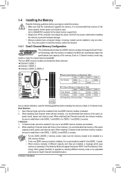
...SS Four Modules DS/SS DS/SS DS/SS DS/SS (SS=Single-Sided, DS=Double-Sided, "- -"=No Memory) DDR3_1 DDR3_3 DDR3_2 DDR3_4 Due to GIGABYTE's website for the latest memory support list.) • Always turn off the computer and unplug the power cord from the power outlet before installing... the memory in Dual/3 Channel mode/performance. When enabling Dual Channel mode with three or four modules, it in Flex Memory Mode will...
...SS Four Modules DS/SS DS/SS DS/SS DS/SS (SS=Single-Sided, DS=Double-Sided, "- -"=No Memory) DDR3_1 DDR3_3 DDR3_2 DDR3_4 Due to GIGABYTE's website for the latest memory support list.) • Always turn off the computer and unplug the power cord from the power outlet before installing... the memory in Dual/3 Channel mode/performance. When enabling Dual Channel mode with three or four modules, it in Flex Memory Mode will...
Manual
Page 17
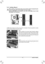
... in the picture on the left, place your memory modules in one direction. Follow the steps below to the memory module. Place the memory module on the memory and insert it can only fit in the memory sockets. 1-4-2 Installing a Memory Before installing a memory module, make sure to turn off the computer ...power outlet to prevent damage to correctly install your fingers on the top edge of the memory module. Notch DDR3 DIMM A DDR3 memory module has a notch, so it vertically into place when the memory module is securely inserted. - 17 - DDR3 and DDR2 DIMMs are not compatible to each...
... in the picture on the left, place your memory modules in one direction. Follow the steps below to the memory module. Place the memory module on the memory and insert it can only fit in the memory sockets. 1-4-2 Installing a Memory Before installing a memory module, make sure to turn off the computer ...power outlet to prevent damage to correctly install your fingers on the top edge of the memory module. Notch DDR3 DIMM A DDR3 memory module has a notch, so it vertically into place when the memory module is securely inserted. - 17 - DDR3 and DDR2 DIMMs are not compatible to each...
Manual
Page 36
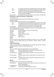
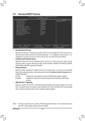
... will exit BIOS Setup. (Pressing can also carry out this task.) BIOS Setup - 36 - Pressing to load the BIOS settings from BIOS If your CPU, memory, etc. Standard CMOS Features Use this menu to configure the system time and date, hard drive types, floppy disk drive types, and the type...
... will exit BIOS Setup. (Pressing can also carry out this task.) BIOS Setup - 36 - Pressing to load the BIOS settings from BIOS If your CPU, memory, etc. Standard CMOS Features Use this menu to configure the system time and date, hard drive types, floppy disk drive types, and the type...
Manual
Page 37
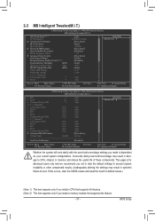
...Link Speed } UnCore & QPI Features Base Clock(BCLK) Control x BCLK Frequency (Mhz) } Advanced Clock Control Performance Enhance Extreme Memory Profile (X.M.P.) (Note 2) System Memory Multiplier (SPD) Memory Frequency (Mhz) 1066 DRAM Timing Selectable (SPD) Profile DDR Voltage Profile QPI Voltage >>>>> Channel A x CAS Latency Time 7 ... stably with the overclock/overvoltage settings you made is for advanced users only and we recommend you install a memory module that supports this feature. (Note 2) This item appears only if you not to alter the default ...
...Link Speed } UnCore & QPI Features Base Clock(BCLK) Control x BCLK Frequency (Mhz) } Advanced Clock Control Performance Enhance Extreme Memory Profile (X.M.P.) (Note 2) System Memory Multiplier (SPD) Memory Frequency (Mhz) 1066 DRAM Timing Selectable (SPD) Profile DDR Voltage Profile QPI Voltage >>>>> Channel A x CAS Latency Time 7 ... stably with the overclock/overvoltage settings you made is for advanced users only and we recommend you install a memory module that supports this feature. (Note 2) This item appears only if you not to alter the default ...
Manual
Page 42
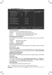
... to Disabled, this item will display as 1.5V. Auto sets memory multiplier according to memory SPD data. (Default: Auto) Memory Frequency(Mhz) The first memory frequency value is set to Profile1 or Profile2, this item will .... ******** Advanced DRAM Features ******** CMOS Setup Utility-Copyright (C) 1984-2009 Award Software Advanced DRAM Features Performance Enhance Extreme Memory Profile (X.M.P.) (Note) System Memory Multiplier (SPD) Memory Frequency(Mhz) 1066 DRAM Timing Selectable (SPD) Profile DDR Voltage Profile QPI Voltage >>>>> Channel A } Channel A ...
... to Disabled, this item will display as 1.5V. Auto sets memory multiplier according to memory SPD data. (Default: Auto) Memory Frequency(Mhz) The first memory frequency value is set to Profile1 or Profile2, this item will .... ******** Advanced DRAM Features ******** CMOS Setup Utility-Copyright (C) 1984-2009 Award Software Advanced DRAM Features Performance Enhance Extreme Memory Profile (X.M.P.) (Note) System Memory Multiplier (SPD) Memory Frequency(Mhz) 1066 DRAM Timing Selectable (SPD) Profile DDR Voltage Profile QPI Voltage >>>>> Channel A } Channel A ...
Manual
Page 48
... F6: Fail-Safe Defaults ESC: Exit F1: General Help F7: Optimized Defaults CMOS Setup Utility-Copyright (C) 1984-2009 Award Software Standard CMOS Features Base Memory Extended Memory Total Memory 640K 1022M 1024M Item Help Menu Level Move Enter: Select F5: Previous Values +/-/PU/PD: Value F10: Save F6: Fail-Safe Defaults ESC...
... F6: Fail-Safe Defaults ESC: Exit F1: General Help F7: Optimized Defaults CMOS Setup Utility-Copyright (C) 1984-2009 Award Software Standard CMOS Features Base Memory Extended Memory Total Memory 640K 1022M 1024M Item Help Menu Level Move Enter: Select F5: Previous Values +/-/PU/PD: Value F10: Save F6: Fail-Safe Defaults ESC...
Manual
Page 49
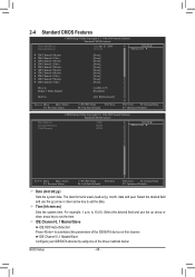
...-DOS operating system. Precomp Write precompensation cylinder. Landing Zone Landing zone. Floppy 3 Mode Support Allows you to the information on this item to None. Extended Memory The amount of sectors. Options are : Auto (default), CHS, LBA, Large. Typically, 640 KB will stop for an error during the POST. Capacity Approximate capacity...
...-DOS operating system. Precomp Write precompensation cylinder. Landing Zone Landing zone. Floppy 3 Mode Support Allows you to the information on this item to None. Extended Memory The amount of sectors. Options are : Auto (default), CHS, LBA, Large. Typically, 640 KB will stop for an error during the POST. Capacity Approximate capacity...
Manual
Page 50
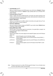
..., Hard Disk, CDROM, ZIP, USB-FDD, USB-ZIP, USB-CDROM, USB-HDD, Legacy LAN, Disabled. After configuring this menu when finished. to 3 (Note) No-Execute Memory Protect (Note) Delay For HDD (Secs) Full Screen LOGO Show Backup BIOS Image to HDD Init Display First [Press Enter] [Floppy] [Hard Disk] [CDROM] [Setup...
..., Hard Disk, CDROM, ZIP, USB-FDD, USB-ZIP, USB-CDROM, USB-HDD, Legacy LAN, Disabled. After configuring this menu when finished. to 3 (Note) No-Execute Memory Protect (Note) Delay For HDD (Secs) Full Screen LOGO Show Backup BIOS Image to HDD Init Display First [Press Enter] [Floppy] [Hard Disk] [CDROM] [Setup...
Manual
Page 51
... hard drive. PCIE x4-1 Sets the PCI Express graphics card on the first PCI Express x16 slot (PCIEX16_1) as Windows NT4.0. (Default: Disabled) No-Execute Memory Protect (Note) Enables or disables Intel Execute Disable Bit function. Limit CPUID Max. Disabled displays normal POST message. (Default: Enabled) Backup BIOS Image to HDD...
... hard drive. PCIE x4-1 Sets the PCI Express graphics card on the first PCI Express x16 slot (PCIEX16_1) as Windows NT4.0. (Default: Disabled) No-Execute Memory Protect (Note) Enables or disables Intel Execute Disable Bit function. Limit CPUID Max. Disabled displays normal POST message. (Default: Enabled) Backup BIOS Image to HDD...
Manual
Page 56
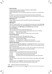
..., or the settings may not be turned on this item and set a password with 1~5 characters to turn on upon the return of the AC power. Memory The system returns to its last known awake state upon the return of the AC power. When prompted for your Windows Vista operating system. Resume...
..., or the settings may not be turned on this item and set a password with 1~5 characters to turn on upon the return of the AC power. Memory The system returns to its last known awake state upon the return of the AC power. When prompted for your Windows Vista operating system. Resume...
Manual
Page 67
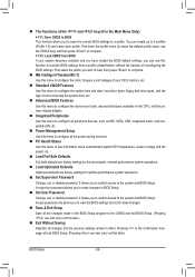
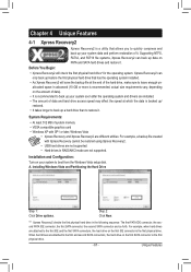
... operating system and drivers are installed. • The amount of data and hard drive access speed may affect the speed at the end of system memory • VESA compatible graphics card • Windows XP with Xpress Recovery cannot be restored using Xpress Recovery2. • USB hard drives are not supported. •...
... operating system and drivers are installed. • The amount of data and hard drive access speed may affect the speed at the end of system memory • VESA compatible graphics card • Windows XP with Xpress Recovery cannot be restored using Xpress Recovery2. • USB hard drives are not supported. •...
Manual
Page 74
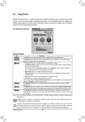
...choose the alert sound from a profile. The Smart tab allows you to the hardware components such as CPU, chipset, and memory and reduce the useful life of CPU frequency/base clock to choose to achieve desired system performance. (Note) After making changes ...monitor hardware temperature, voltage and fan speed and set . Incorrectly doing overclock/overvoltage may differ by motherboard model. 4-3 EasyTune 6 GIGABYTE's EasyTune 6 is not supported. Before you to default values. Available functions in Windows environment. The Tuner tab allows you to...
...choose the alert sound from a profile. The Smart tab allows you to the hardware components such as CPU, chipset, and memory and reduce the useful life of CPU frequency/base clock to choose to achieve desired system performance. (Note) After making changes ...monitor hardware temperature, voltage and fan speed and set . Incorrectly doing overclock/overvoltage may differ by motherboard model. 4-3 EasyTune 6 GIGABYTE's EasyTune 6 is not supported. Before you to default values. Available functions in Windows environment. The Tuner tab allows you to...
Manual
Page 81
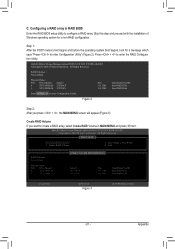
... Create RAID Volume in RAID BIOS Enter the RAID BIOS setup utility to configure a RAID array. All Rights Reversed. [ MAIN MENU ] 1. Step 1: After the POST memory test begins and before the operating system boot begins, look for a non-RAID configuration. Intel(R) Matrix Storage Manager option ROM v8.0.0.1039 ICH10R wRAID5 Copyright...
... Create RAID Volume in RAID BIOS Enter the RAID BIOS setup utility to configure a RAID array. All Rights Reversed. [ MAIN MENU ] 1. Step 1: After the POST memory test begins and before the operating system boot begins, look for a non-RAID configuration. Intel(R) Matrix Storage Manager option ROM v8.0.0.1039 ICH10R wRAID5 Copyright...
Manual
Page 86
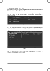
After the POST memory test begins and before the operating system boot begins, look for a non-RAID... ST3120026AS 120 GB 120 GB Non-RAID Non-RAID ODD0 : DVDROM GO-D1600B Press to enter the GIGABYTE SATA2 RAID BIOS utility. GIGABYTE Technology Corp. C. PCIE-to-SATAII/IDE RAID Controller BIOS v1.06.78 [ Main Menu ] Create...Action [ESC]-Exit Note: In the main screen, you wish to enter RAID Setup Utility" (Figure 2). Appendix - 86 - GIGABYTE Technology Corp. Press + to enter RAID Setup Utility ... Figure 2 In the main screen of Windows operating system for a message ...
After the POST memory test begins and before the operating system boot begins, look for a non-RAID... ST3120026AS 120 GB 120 GB Non-RAID Non-RAID ODD0 : DVDROM GO-D1600B Press to enter the GIGABYTE SATA2 RAID BIOS utility. GIGABYTE Technology Corp. C. PCIE-to-SATAII/IDE RAID Controller BIOS v1.06.78 [ Main Menu ] Create...Action [ESC]-Exit Note: In the main screen, you wish to enter RAID Setup Utility" (Figure 2). Appendix - 86 - GIGABYTE Technology Corp. Press + to enter RAID Setup Utility ... Figure 2 In the main screen of Windows operating system for a message ...


