
Manual
Page 1
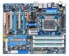
GA-EX58-EXTREME LGA1366 socket motherboard for Intel® CoreTM i7 processor family User's Manual Rev. 1004 12ME-EX58EX-1004R
GA-EX58-EXTREME LGA1366 socket motherboard for Intel® CoreTM i7 processor family User's Manual Rev. 1004 12ME-EX58EX-1004R

Manual
Page 2
Motherboard GA-EX58-EXTREME Oct. 31, 2008 Motherboard GA-EX58-EXTREME Oct. 31, 2008
Motherboard GA-EX58-EXTREME Oct. 31, 2008 Motherboard GA-EX58-EXTREME Oct. 31, 2008
Manual
Page 3
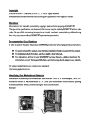
... like this manual may be made by any form or by GIGABYTE without GIGABYTE's prior written permission. The trademarks mentioned in the use GIGABYTE's unique features, read or download the information on/from the Support\Motherboard\Technology Guide page on your motherboard revision before updating motherboard BIOS, drivers, or when looking for technical information. Documentation Classifications...
... like this manual may be made by any form or by GIGABYTE without GIGABYTE's prior written permission. The trademarks mentioned in the use GIGABYTE's unique features, read or download the information on/from the Support\Motherboard\Technology Guide page on your motherboard revision before updating motherboard BIOS, drivers, or when looking for technical information. Documentation Classifications...
Manual
Page 4
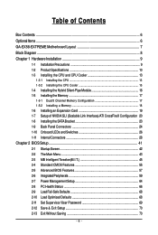
Table of Contents Box Contents ...6 OptionalItems ...6 GA-EX58-EXTREME Motherboard Layout 7 Block Diagram ...8 Chapter 1 Hardware Installation 9 1-1 Installation Precautions 9 1-2 Product Specifications 10 1-3 Installing the CPU and CPU Cooler 13 1-3-1 Installing the CPU 13 1-3-2 Installing the CPU ...
Table of Contents Box Contents ...6 OptionalItems ...6 GA-EX58-EXTREME Motherboard Layout 7 Block Diagram ...8 Chapter 1 Hardware Installation 9 1-1 Installation Precautions 9 1-2 Product Specifications 10 1-3 Installing the CPU and CPU Cooler 13 1-3-1 Installing the CPU 13 1-3-2 Installing the CPU ...
Manual
Page 6
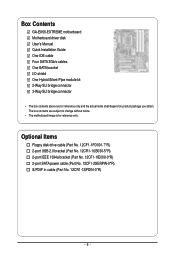
...port SATA power cable (Part No. 12CF1-2SERPW-0*R) S/PDIF in cable (Part No. 12CR1-1SPDIN-0*R) - 6 - The box contents are for reference only. Box Contents GA-EX58-EXTREME motherboard Motherboard driver disk User's Manual Quick Installation Guide One IDE cable Four SATA 3Gb/s cables One SATA bracket I/O shield One Hybrid Silent-Pipe module kit 2-Way... SLI bridge connector 3-Way SLI bridge connector • The box contents above are subject to change without notice. • The motherboard image is for reference only and the actual items shall depend on product package you obtain.
...port SATA power cable (Part No. 12CF1-2SERPW-0*R) S/PDIF in cable (Part No. 12CR1-1SPDIN-0*R) - 6 - The box contents are for reference only. Box Contents GA-EX58-EXTREME motherboard Motherboard driver disk User's Manual Quick Installation Guide One IDE cable Four SATA 3Gb/s cables One SATA bracket I/O shield One Hybrid Silent-Pipe module kit 2-Way... SLI bridge connector 3-Way SLI bridge connector • The box contents above are subject to change without notice. • The motherboard image is for reference only and the actual items shall depend on product package you obtain.
Manual
Page 7
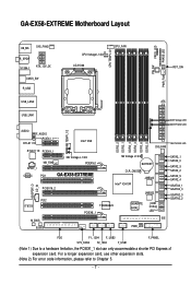
... CODEC NB_FAN PCI1 NB Voltage L1/2/3 PCIEX16_1 GA-EX58-EXTREME PCIEX16_2 DDR3_2 DDR3_1 DDR3_4 DDR3_3 DDR3_6 DDR3_5 SYS_FAN1 SB Voltage L1/2/3 BATTERY CLR_CMOS Intel® ICH10R JMB322 JMB322 SPDIF_O CD_IN PCI2 IT8720 M_BIOS B_BIOS TSB43AB23 PCIEX8_1 GIGABYTE SATA2 PWR_LED CI Debug LED(Note 2) IDE... please refer to a hardware limitation, the PCIEX1_1 slot can only accommodate a shorter PCI Express x1 expansion card. GA-EX58-EXTREME Motherboard Layout KB_MS SYS_FAN3 R_SPDIF V1394-1 ATX_12V_2X CMOS_SW R_USB CPU Voltage L1/2/3 LGA1366 CPU_FAN CPU TEMP L1/2 PW_SW FREQ.
... CODEC NB_FAN PCI1 NB Voltage L1/2/3 PCIEX16_1 GA-EX58-EXTREME PCIEX16_2 DDR3_2 DDR3_1 DDR3_4 DDR3_3 DDR3_6 DDR3_5 SYS_FAN1 SB Voltage L1/2/3 BATTERY CLR_CMOS Intel® ICH10R JMB322 JMB322 SPDIF_O CD_IN PCI2 IT8720 M_BIOS B_BIOS TSB43AB23 PCIEX8_1 GIGABYTE SATA2 PWR_LED CI Debug LED(Note 2) IDE... please refer to a hardware limitation, the PCIEX1_1 slot can only accommodate a shorter PCI Express x1 expansion card. GA-EX58-EXTREME Motherboard Layout KB_MS SYS_FAN3 R_SPDIF V1394-1 ATX_12V_2X CMOS_SW R_USB CPU Voltage L1/2/3 LGA1366 CPU_FAN CPU TEMP L1/2 PW_SW FREQ.
Manual
Page 9
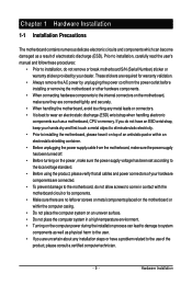
...hardware components to the internal connectors on the power, make sure they are connected tightly and securely. • When handling the motherboard, avoid touching any installation steps or have an ESD wrist strap, keep your dealer. If you are uncertain about any metal...wrist strap when handling electronic components such as a result of electrostatic discharge (ESD). Chapter 1 Hardware Installation 1-1 Installation Precautions The motherboard contains numerous delicate electronic circuits and components which can lead to damage to system components as well as physical harm to the user...
...hardware components to the internal connectors on the power, make sure they are connected tightly and securely. • When handling the motherboard, avoid touching any installation steps or have an ESD wrist strap, keep your dealer. If you are uncertain about any metal...wrist strap when handling electronic components such as a result of electrostatic discharge (ESD). Chapter 1 Hardware Installation 1-1 Installation Precautions The motherboard contains numerous delicate electronic circuits and components which can lead to damage to system components as well as physical harm to the user...
Manual
Page 10
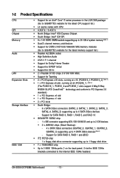
...Interface IEEE 1394 Support for an Intel® CoreTM i7 series processor in the LGA1366 package (Go to GIGABYTE's website for the latest CPU support list.) L3 cache varies with CPU 4.8GT/s / 6.... Dual/3 channel memory architecture Support for DDR3 2100/1333/1066/800 MHz memory modules (Go to GIGABYTE's website for the latest memory support list.) Realtek ALC889A codec High Definition Audio 2/4/5.1/7.1-channel... 2 via the IEEE 1394a brackets connected to the internal IEEE 1394a headers) GA-EX58-EXTREME Motherboard - 10 -
...Interface IEEE 1394 Support for an Intel® CoreTM i7 series processor in the LGA1366 package (Go to GIGABYTE's website for the latest CPU support list.) L3 cache varies with CPU 4.8GT/s / 6.... Dual/3 channel memory architecture Support for DDR3 2100/1333/1066/800 MHz memory modules (Go to GIGABYTE's website for the latest memory support list.) Realtek ALC889A codec High Definition Audio 2/4/5.1/7.1-channel... 2 via the IEEE 1394a brackets connected to the internal IEEE 1394a headers) GA-EX58-EXTREME Motherboard - 10 -
Manual
Page 12
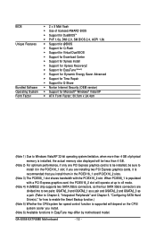
... chip supports two SATA 3Gb/s connectors, so the four SATA 3Gb/s connectors are installing two PCI Express graphics cards, it in EasyTune may differ by motherboard model. When PCIEX8_1 is populated with the PCIEX16_2 slot. BIOS Unique Features Bundled Software Operating System Form Factor 2 x 8 Mbit flash Use of licensed... Express graphics card, the PCIEX16_2 slot will operate at up to install it is recommended that you install. (Note 6) Available functions in the PCIEX16_1 slot; GA-EX58-EXTREME Motherboard - 12 -
... chip supports two SATA 3Gb/s connectors, so the four SATA 3Gb/s connectors are installing two PCI Express graphics cards, it in EasyTune may differ by motherboard model. When PCIEX8_1 is populated with the PCIEX16_2 slot. BIOS Unique Features Bundled Software Operating System Form Factor 2 x 8 Mbit flash Use of licensed... Express graphics card, the PCIEX16_2 slot will operate at up to install it is recommended that you install. (Note 6) Available functions in the PCIEX16_1 slot; GA-EX58-EXTREME Motherboard - 12 -
Manual
Page 13
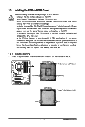
...of the CPU may occur. • Set the CPU host frequency in accordance with the CPU specifications. Locate the alignment keys on the motherboard CPU socket and the notches on the CPU Notch Notch - 13 - LGA1366 CPUSocket Pin One Corner of the CPU Socket Alignment Key Alignment... Key LGA1366 CPU Triangle Pin One Marking on the CPU. mended that the motherboard supports the CPU. (Go to GIGABYTE's website for the peripherals. 1-3 Installing the CPU and CPU Cooler Read the following guidelines before installing the CPU to prevent...
...of the CPU may occur. • Set the CPU host frequency in accordance with the CPU specifications. Locate the alignment keys on the motherboard CPU socket and the notches on the CPU Notch Notch - 13 - LGA1366 CPUSocket Pin One Corner of the CPU Socket Alignment Key Alignment... Key LGA1366 CPU Triangle Pin One Marking on the CPU. mended that the motherboard supports the CPU. (Go to GIGABYTE's website for the peripherals. 1-3 Installing the CPU and CPU Cooler Read the following guidelines before installing the CPU to prevent...
Manual
Page 14
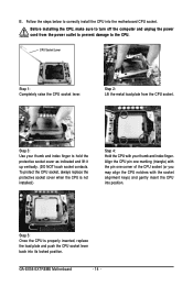
...from the CPU socket. Step 2: Lift the metal load plate from the power outlet to prevent damage to correctly install the CPU into the motherboard CPU socket. Step 5: Once the CPU is not installed.) Step 4: Hold the CPU with the socket alignment keys) and gently insert the...with your thumb and index finger to hold the protective socket cover as indicated and lift it up vertically. (DO NOT touch socket contacts. GA-EX58-EXTREME Motherboard - 14 - CPU Socket Lever Step 1: Completely raise the CPU socket lever. To protect the CPU socket, always replace the protective socket cover...
...from the CPU socket. Step 2: Lift the metal load plate from the power outlet to prevent damage to correctly install the CPU into the motherboard CPU socket. Step 5: Once the CPU is not installed.) Step 4: Hold the CPU with the socket alignment keys) and gently insert the...with your thumb and index finger to hold the protective socket cover as indicated and lift it up vertically. (DO NOT touch socket contacts. GA-EX58-EXTREME Motherboard - 14 - CPU Socket Lever Step 1: Completely raise the CPU socket lever. To protect the CPU socket, always replace the protective socket cover...
Manual
Page 15
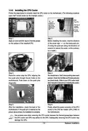
... attach the power connector of the installed CPU. 1-3-2 Installing the CPU Cooler Follow the steps below to correctly install the CPU cooler on the motherboard. (The following procedure uses Intel® boxed cooler as the picture above shows, the installation is to install.) Step 3: Place the cooler atop... the CPU, aligning the four push pins through the pin holes on the motherboard. Use extreme care when removing the CPU cooler because the thermal grease/tape between the CPU cooler and CPU may damage the CPU. - 15 - ...
... attach the power connector of the installed CPU. 1-3-2 Installing the CPU Cooler Follow the steps below to correctly install the CPU cooler on the motherboard. (The following procedure uses Intel® boxed cooler as the picture above shows, the installation is to install.) Step 3: Place the cooler atop... the CPU, aligning the four push pins through the pin holes on the motherboard. Use extreme care when removing the CPU cooler because the thermal grease/tape between the CPU cooler and CPU may damage the CPU. - 15 - ...
Manual
Page 16
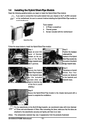
...to avoid interference. Step 2: Position the heatpipe underneath the heatsink of the Hybrid Silent-Pipe module into the tunnel of 10mm. Thermal grease 3. GA-EX58-EXTREME Motherboard - 16 - For the waterblocks on the North Bridge heatsink, we recommend tubes with inner diameter of 7.5mm and outer diameter of the ...tightly and there is no leak. (Note) The components received may vary in appearance from your chassis to the F_AUDIO connector on the motherboard, be sure to connect it before installing the Hybrid Silent-Pipe module to install the Hybrid Silent-Pipe module: Step 1: Apply an ...
...to avoid interference. Step 2: Position the heatpipe underneath the heatsink of the Hybrid Silent-Pipe module into the tunnel of 10mm. Thermal grease 3. GA-EX58-EXTREME Motherboard - 16 - For the waterblocks on the North Bridge heatsink, we recommend tubes with inner diameter of 7.5mm and outer diameter of the ...tightly and there is no leak. (Note) The components received may vary in appearance from your chassis to the F_AUDIO connector on the motherboard, be sure to connect it before installing the Hybrid Silent-Pipe module to install the Hybrid Silent-Pipe module: Step 1: Apply an ...
Manual
Page 17
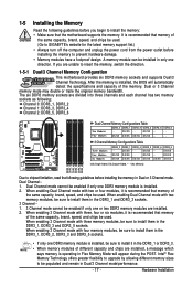
... same capacity, brand, speed, and chips be sure to insert the memory, switch the direction. 1-5-1 Dual/3 Channel Memory Configuration This motherboard provides six DDR3 memory sockets and supports Dual/3 Channel Technology. It is operating in Flex Memory Mode will automatically detect the specifications and... damage. • Memory modules have a foolproof design. When enabling Dual Channel mode with three memory modules, be used . (Go to GIGABYTE's website for the latest memory support list.) • Always turn off the computer and unplug the power cord from the power outlet before...
... same capacity, brand, speed, and chips be sure to insert the memory, switch the direction. 1-5-1 Dual/3 Channel Memory Configuration This motherboard provides six DDR3 memory sockets and supports Dual/3 Channel Technology. It is operating in Flex Memory Mode will automatically detect the specifications and... damage. • Memory modules have a foolproof design. When enabling Dual Channel mode with three memory modules, be used . (Go to GIGABYTE's website for the latest memory support list.) • Always turn off the computer and unplug the power cord from the power outlet before...
Manual
Page 18
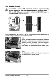
... module has a notch, so it vertically into place when the memory module is securely inserted. Place the memory module on this motherboard. Step 1: Note the orientation of the memory socket. GA-EX58-EXTREME Motherboard - 18 - Spread the retaining clips at both ends of the memory module. 1-5-2 Installing a Memory Before installing a memory module , make sure to...
... module has a notch, so it vertically into place when the memory module is securely inserted. Place the memory module on this motherboard. Step 1: Note the orientation of the memory socket. GA-EX58-EXTREME Motherboard - 18 - Spread the retaining clips at both ends of the memory module. 1-5-2 Installing a Memory Before installing a memory module , make sure to...
Manual
Page 19
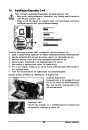
... the PCI Express slot to prevent hardware damage. Hardware Installation If necessary, go to BIOS Setup to install an expansion card: • Make sure the motherboard supports the expansion card. 1-6 Installing an Expansion Card Read the following guidelines before installing an expansion card to release the card and then pull the...
... the PCI Express slot to prevent hardware damage. Hardware Installation If necessary, go to BIOS Setup to install an expansion card: • Make sure the motherboard supports the expansion card. 1-6 Installing an Expansion Card Read the following guidelines before installing an expansion card to release the card and then pull the...
Manual
Page 20
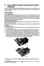
... 2) , be sure to use is able to provide sufficient power to bridge two or three PCI ExpressTM graphics cards! Note that provides at least 1000W. GA-EX58-EXTREME Motherboard - 20 - Figure 1 Figure 2 (Note) To set up a 3-Way CrossFireX configuration, install the bridge connector (optional) shown in your overall system configurations. 2. Supported Operation Systems: Windows...
... 2) , be sure to use is able to provide sufficient power to bridge two or three PCI ExpressTM graphics cards! Note that provides at least 1000W. GA-EX58-EXTREME Motherboard - 20 - Figure 1 Figure 2 (Note) To set up a 3-Way CrossFireX configuration, install the bridge connector (optional) shown in your overall system configurations. 2. Supported Operation Systems: Windows...
Manual
Page 22
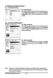
... enabled. C-2 To enable CrossFireX function For 2-Way CrossFireX: After installing graphics card driver in the operating system, go to the SLI and Physx configuration screen. GA-EX58-EXTREME Motherboard - 22 - C. Browse to the Catalyst Control Center. For 3-Way CrossFireX: Browse to the manual that came with your graphics cards for enabling SLI/CrossFireX technology...
... enabled. C-2 To enable CrossFireX function For 2-Way CrossFireX: After installing graphics card driver in the operating system, go to the SLI and Physx configuration screen. GA-EX58-EXTREME Motherboard - 22 - C. Browse to the Catalyst Control Center. For 3-Way CrossFireX: Browse to the manual that came with your graphics cards for enabling SLI/CrossFireX technology...
Manual
Page 23
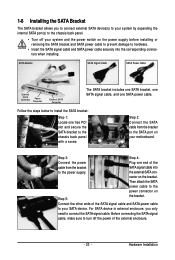
... The SATA bracket includes one SATA bracket, one SATA signal cable, and one free PCI slot and secure the SATA bracket to turn off your motherboard. Connect the other ends of the SATA signal cable and SATA power cable to the SATA port on your system and the power switch on...
... The SATA bracket includes one SATA bracket, one SATA signal cable, and one free PCI slot and secure the SATA bracket to turn off your motherboard. Connect the other ends of the SATA signal cable and SATA power cable to the SATA port on your system and the power switch on...
Manual
Page 24
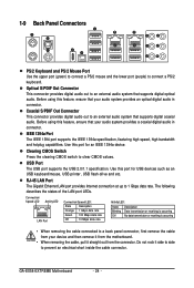
...port for an IEEE 1394a device. RJ-45 LAN Port The Gigabit Ethernet LAN port provides Internet connection at up to clear CMOS values. GA-EX58-EXTREME Motherboard - 24 - Optical S/PDIF Out Connector This connector provides digital audio out to an external audio system that your device and then remove... it from the motherboard. • When removing the cable, pull it straight out from the connector. IEEE 1394a Port The IEEE 1394 port supports the IEEE ...
...port for an IEEE 1394a device. RJ-45 LAN Port The Gigabit Ethernet LAN port provides Internet connection at up to clear CMOS values. GA-EX58-EXTREME Motherboard - 24 - Optical S/PDIF Out Connector This connector provides digital audio out to an external audio system that your device and then remove... it from the motherboard. • When removing the cable, pull it straight out from the connector. IEEE 1394a Port The IEEE 1394 port supports the IEEE ...


