
Manual
Page 1
GA-EX58-EXTREME LGA1366 socket motherboard for Intel® CoreTM i7 processor family User's Manual Rev. 1004 12ME-EX58EX-1004R
GA-EX58-EXTREME LGA1366 socket motherboard for Intel® CoreTM i7 processor family User's Manual Rev. 1004 12ME-EX58EX-1004R

Manual
Page 2
Motherboard GA-EX58-EXTREME Oct. 31, 2008 Motherboard GA-EX58-EXTREME Oct. 31, 2008
Motherboard GA-EX58-EXTREME Oct. 31, 2008 Motherboard GA-EX58-EXTREME Oct. 31, 2008
Manual
Page 3
...drivers, or when looking for technical information. For product-related information, check on our website at: http://www.gigabyte.com.tw Identifying Your Motherboard Revision The revision number on how to their respective owners. Documentation Classifications In order to assist in this manual ...are legally registered to use of this : "REV: X.X." Check your motherboard looks like this product, GIGABYTE provides the following types of documentations: For quick set-up of the motherboard is the property of this manual may be made by any means without prior notice...
...drivers, or when looking for technical information. For product-related information, check on our website at: http://www.gigabyte.com.tw Identifying Your Motherboard Revision The revision number on how to their respective owners. Documentation Classifications In order to assist in this manual ...are legally registered to use of this : "REV: X.X." Check your motherboard looks like this product, GIGABYTE provides the following types of documentations: For quick set-up of the motherboard is the property of this manual may be made by any means without prior notice...
Manual
Page 4
Table of Contents Box Contents ...6 OptionalItems ...6 GA-EX58-EXTREME Motherboard Layout 7 Block Diagram ...8 Chapter 1 Hardware Installation 9 1-1 Installation Precautions 9 1-2 Product Specifications 10 1-3 Installing the CPU and CPU Cooler 13 1-3-1 Installing the CPU 13 1-3-2 Installing the CPU ...
Table of Contents Box Contents ...6 OptionalItems ...6 GA-EX58-EXTREME Motherboard Layout 7 Block Diagram ...8 Chapter 1 Hardware Installation 9 1-1 Installation Precautions 9 1-2 Product Specifications 10 1-3 Installing the CPU and CPU Cooler 13 1-3-1 Installing the CPU 13 1-3-2 Installing the CPU ...
Manual
Page 6
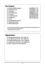
... SATA power cable (Part No. 12CF1-2SERPW-0*R) S/PDIF in cable (Part No. 12CR1-1SPDIN-0*R) - 6 - The box contents are for reference only. Box Contents GA-EX58-EXTREME motherboard Motherboard driver disk User's Manual Quick Installation Guide One IDE cable Four SATA 3Gb/s cables One SATA bracket I/O shield One Hybrid Silent-Pipe module kit 2-Way... SLI bridge connector 3-Way SLI bridge connector • The box contents above are subject to change without notice. • The motherboard image is for reference only and the actual items shall depend on product package you obtain.
... SATA power cable (Part No. 12CF1-2SERPW-0*R) S/PDIF in cable (Part No. 12CR1-1SPDIN-0*R) - 6 - The box contents are for reference only. Box Contents GA-EX58-EXTREME motherboard Motherboard driver disk User's Manual Quick Installation Guide One IDE cable Four SATA 3Gb/s cables One SATA bracket I/O shield One Hybrid Silent-Pipe module kit 2-Way... SLI bridge connector 3-Way SLI bridge connector • The box contents above are subject to change without notice. • The motherboard image is for reference only and the actual items shall depend on product package you obtain.
Manual
Page 7
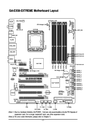
...CODEC NB_FAN PCI1 NB Voltage L1/2/3 PCIEX16_1 GA-EX58-EXTREME PCIEX16_2 DDR3_2 DDR3_1 DDR3_4 DDR3_3 DDR3_6 DDR3_5 SYS_FAN1 SB Voltage L1/2/3 BATTERY CLR_CMOS Intel® ICH10R JMB322 JMB322 SPDIF_O CD_IN PCI2 IT8720 M_BIOS B_BIOS TSB43AB23 PCIEX8_1 GIGABYTE SATA2 PWR_LED CI Debug LED(Note 2) IDE...please refer to a hardware limitation, the PCIEX1_1 slot can only accommodate a shorter PCI Express x1 expansion card. GA-EX58-EXTREME Motherboard Layout KB_MS SYS_FAN3 R_SPDIF V1394-1 ATX_12V_2X CMOS_SW R_USB CPU Voltage L1/2/3 LGA1366 CPU_FAN CPU TEMP L1/2 PW_SW FREQ.
...CODEC NB_FAN PCI1 NB Voltage L1/2/3 PCIEX16_1 GA-EX58-EXTREME PCIEX16_2 DDR3_2 DDR3_1 DDR3_4 DDR3_3 DDR3_6 DDR3_5 SYS_FAN1 SB Voltage L1/2/3 BATTERY CLR_CMOS Intel® ICH10R JMB322 JMB322 SPDIF_O CD_IN PCI2 IT8720 M_BIOS B_BIOS TSB43AB23 PCIEX8_1 GIGABYTE SATA2 PWR_LED CI Debug LED(Note 2) IDE...please refer to a hardware limitation, the PCIEX1_1 slot can only accommodate a shorter PCI Express x1 expansion card. GA-EX58-EXTREME Motherboard Layout KB_MS SYS_FAN3 R_SPDIF V1394-1 ATX_12V_2X CMOS_SW R_USB CPU Voltage L1/2/3 LGA1366 CPU_FAN CPU TEMP L1/2 PW_SW FREQ.
Manual
Page 9
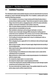
...verify that all cables and power connectors of your hands dry and first touch a metal object to eliminate static electricity. • Prior to installing the motherboard, please have a problem related to come in a high-temperature environment. • Turning on an uneven surface. • Do not place the ...been turned off. • Before turning on the power, make sure they are no leftover screws or metal components placed on the motherboard or within the computer casing. • Do not place the computer system on the computer power during the installation process can become damaged ...
...verify that all cables and power connectors of your hands dry and first touch a metal object to eliminate static electricity. • Prior to installing the motherboard, please have a problem related to come in a high-temperature environment. • Turning on an uneven surface. • Do not place the ...been turned off. • Before turning on the power, make sure they are no leftover screws or metal components placed on the motherboard or within the computer casing. • Do not place the computer system on the computer power during the installation process can become damaged ...
Manual
Page 10
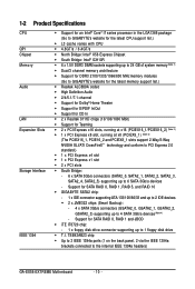
...Note 1) Dual/3 channel memory architecture Support for DDR3 2100/1333/1066/800 MHz memory modules (Go to GIGABYTE's website for the latest memory support list.) Realtek ALC889A codec High Definition Audio 2/4/5.1/7.1-channel &#...RAID 5, and RAID 10 GIGABYTE SATA2 chip: - 1 x IDE connector supporting ATA-133/100/66/33 and up to 2 IDE devices 2 x JMB322 chips (Smart Backup): - 4 x SATA 3Gb/s connectors (GSATA2_0, GSATA2_1, GSATA2_2, GSATA2_3) supporting up to the internal IEEE 1394a headers) GA-EX58-EXTREME Motherboard - 10 -
...Note 1) Dual/3 channel memory architecture Support for DDR3 2100/1333/1066/800 MHz memory modules (Go to GIGABYTE's website for the latest memory support list.) Realtek ALC889A codec High Definition Audio 2/4/5.1/7.1-channel &#...RAID 5, and RAID 10 GIGABYTE SATA2 chip: - 1 x IDE connector supporting ATA-133/100/66/33 and up to 2 IDE devices 2 x JMB322 chips (Smart Backup): - 4 x SATA 3Gb/s connectors (GSATA2_0, GSATA2_1, GSATA2_2, GSATA2_3) supporting up to the internal IEEE 1394a headers) GA-EX58-EXTREME Motherboard - 10 -
Manual
Page 12
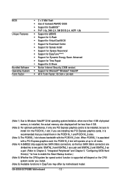
GA-EX58-EXTREME Motherboard - 12 - When PCIEX8_1 is populated with the PCIEX16_2 slot. if you are divided into to two pairs: GSATA2_0 and GSATA2_1 as a pair and GSATA2_2 and ... chip supports two SATA 3Gb/s connectors, so the four SATA 3Gb/s connectors are installing two PCI Express graphics cards, it in EasyTune may differ by motherboard model.
GA-EX58-EXTREME Motherboard - 12 - When PCIEX8_1 is populated with the PCIEX16_2 slot. if you are divided into to two pairs: GSATA2_0 and GSATA2_1 as a pair and GSATA2_2 and ... chip supports two SATA 3Gb/s connectors, so the four SATA 3Gb/s connectors are installing two PCI Express graphics cards, it in EasyTune may differ by motherboard model.
Manual
Page 13
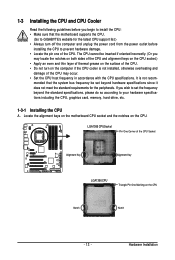
... the CPU to prevent hardware damage. • Locate the pin one of the CPU. mended that the motherboard supports the CPU. (Go to GIGABYTE's website for the peripherals. Locate the alignment keys on the motherboard CPU socket and the notches on the computer if the CPU cooler is not recom- The CPU cannot...
... the CPU to prevent hardware damage. • Locate the pin one of the CPU. mended that the motherboard supports the CPU. (Go to GIGABYTE's website for the peripherals. Locate the alignment keys on the motherboard CPU socket and the notches on the computer if the CPU cooler is not recom- The CPU cannot...
Manual
Page 14
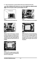
... the CPU. Step 5: Once the CPU is not installed.) Step 4: Hold the CPU with the socket alignment keys) and gently insert the CPU into the motherboard CPU socket. B. To protect the CPU socket, always replace the protective socket cover when the CPU is properly inserted, replace the load plate and push... into its locked position. Follow the steps below to correctly install the CPU into position. CPU Socket Lever Step 1: Completely raise the CPU socket lever. GA-EX58-EXTREME Motherboard - 14 -
... the CPU. Step 5: Once the CPU is not installed.) Step 4: Hold the CPU with the socket alignment keys) and gently insert the CPU into the motherboard CPU socket. B. To protect the CPU socket, always replace the protective socket cover when the CPU is properly inserted, replace the load plate and push... into its locked position. Follow the steps below to correctly install the CPU into position. CPU Socket Lever Step 1: Completely raise the CPU socket lever. GA-EX58-EXTREME Motherboard - 14 -
Manual
Page 15
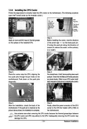
...when pushing down on the push pins diagonally. Hardware Installation Push down each push pin. Step 6: Finally, attach the power connector of the motherboard. Use extreme care when removing the CPU cooler because the thermal grease/tape between the CPU cooler and CPU may damage the CPU. - 15 - 1-3-2... Installing the CPU Cooler Follow the steps below to correctly install the CPU cooler on the motherboard. (The following procedure uses Intel&#...
...when pushing down on the push pins diagonally. Hardware Installation Push down each push pin. Step 6: Finally, attach the power connector of the motherboard. Use extreme care when removing the CPU cooler because the thermal grease/tape between the CPU cooler and CPU may damage the CPU. - 15 - 1-3-2... Installing the CPU Cooler Follow the steps below to correctly install the CPU cooler on the motherboard. (The following procedure uses Intel&#...
Manual
Page 16
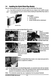
... and there is no leak. (Note) The components received may vary in appearance from your chassis to the F_AUDIO connector on the motherboard, be sure to connect it grooves. For the waterblocks on the left shows that the tubes are fastened to complete the installation. Tools... front audio module from the products illustrated. Screws included with inner diameter of 7.5mm and outer diameter of the North Bridge heasink base. GA-EX58-EXTREME Motherboard - 16 - Step 2: Position the heatpipe underneath the heatsink of the Hybrid Silent-Pipe module into the tunnel of 10mm. Step 3:...
... and there is no leak. (Note) The components received may vary in appearance from your chassis to the F_AUDIO connector on the motherboard, be sure to connect it grooves. For the waterblocks on the left shows that the tubes are fastened to complete the installation. Tools... front audio module from the products illustrated. Screws included with inner diameter of 7.5mm and outer diameter of the North Bridge heasink base. GA-EX58-EXTREME Motherboard - 16 - Step 2: Position the heatpipe underneath the heatsink of the Hybrid Silent-Pipe module into the tunnel of 10mm. Step 3:...
Manual
Page 17
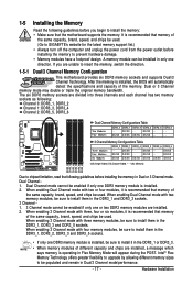
... Four Modules DDR3_2 - Dual Channel-1. Hardware Installation It is installed, be used. Dual Channel mode cannot be used . (Go to GIGABYTE's website for the latest memory support list.) • Always turn off the computer and unplug the power cord from the power outlet ...the Memory Read the following guidelines before you are unable to insert the memory, switch the direction. 1-5-1 Dual/3 Channel Memory Configuration This motherboard provides six DDR3 memory sockets and supports Dual/3 Channel Technology. A memory module can be populated and remain in only one DDR3 memory ...
... Four Modules DDR3_2 - Dual Channel-1. Hardware Installation It is installed, be used. Dual Channel mode cannot be used . (Go to GIGABYTE's website for the latest memory support list.) • Always turn off the computer and unplug the power cord from the power outlet ...the Memory Read the following guidelines before you are unable to insert the memory, switch the direction. 1-5-1 Dual/3 Channel Memory Configuration This motherboard provides six DDR3 memory sockets and supports Dual/3 Channel Technology. A memory module can be populated and remain in only one DDR3 memory ...
Manual
Page 18
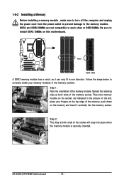
... the picture on the memory and insert it can only fit in the memory sockets. Step 2: The clips at both ends of the memory socket. GA-EX58-EXTREME Motherboard - 18 - Step 1: Note the orientation of the memory, push down on the left, place your memory modules in one direction. Spread the retaining clips at... the power outlet to prevent damage to correctly install your fingers on the top edge of the memory module. Place the memory module on this motherboard.
... the picture on the memory and insert it can only fit in the memory sockets. Step 2: The clips at both ends of the memory socket. GA-EX58-EXTREME Motherboard - 18 - Step 1: Note the orientation of the memory, push down on the left, place your memory modules in one direction. Spread the retaining clips at... the power outlet to prevent damage to correctly install your fingers on the top edge of the memory module. Place the memory module on this motherboard.
Manual
Page 19
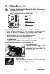
... turn off the computer and unplug the power cord from the power outlet before you begin to install an expansion card: • Make sure the motherboard supports the expansion card. Hardware Installation Secure the card's metal bracket to release the card and then pull the card straight up from the chassis...
... turn off the computer and unplug the power cord from the power outlet before you begin to install an expansion card: • Make sure the motherboard supports the expansion card. Hardware Installation Secure the card's metal bracket to release the card and then pull the card straight up from the chassis...
Manual
Page 20
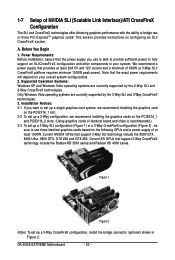
... PCIEX16_2 slots. (Using graphics cards of identical brand and chips is able to provide sufficient power to bridge two or three PCI ExpressTM graphics cards! GA-EX58-EXTREME Motherboard - 20 - Power Requirements: Before installation, assure that support 3-Way CrossFireX technology include the Radeon HD 3800 series and Radeon HD 4800 series. 1-7 Setup of 600W...
... PCIEX16_2 slots. (Using graphics cards of identical brand and chips is able to provide sufficient power to bridge two or three PCI ExpressTM graphics cards! GA-EX58-EXTREME Motherboard - 20 - Power Requirements: Before installation, assure that support 3-Way CrossFireX technology include the Radeon HD 3800 series and Radeon HD 4800 series. 1-7 Setup of 600W...
Manual
Page 22
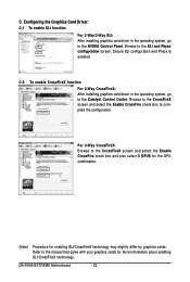
... graphics cards for enabling SLI/CrossFireX technology may slightly differ by graphics cards. Refer to complete the configuration. C. Ensure SLI configuration and Physx is enabled. GA-EX58-EXTREME Motherboard - 22 - Browse to the CrossFireX screen and select the Enable CrossFire check box and also select 3 GPUS for the GPU combination. (Note) Procedure for more...
... graphics cards for enabling SLI/CrossFireX technology may slightly differ by graphics cards. Refer to complete the configuration. C. Ensure SLI configuration and Physx is enabled. GA-EX58-EXTREME Motherboard - 22 - Browse to the CrossFireX screen and select the Enable CrossFire check box and also select 3 GPUS for the GPU combination. (Note) Procedure for more...
Manual
Page 23
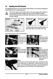
... cable and SATA power cable securely into to the power supply. For SATA device in external enclosure, you to connect external SATA device(s) to your motherboard. 1-8 Installing the SATA Bracket The SATA bracket allows you only need to connect the SATA signal cable. Follow the steps below to your system and...
... cable and SATA power cable securely into to the power supply. For SATA device in external enclosure, you to connect external SATA device(s) to your motherboard. 1-8 Installing the SATA Bracket The SATA bracket allows you only need to connect the SATA signal cable. Follow the steps below to your system and...
Manual
Page 24
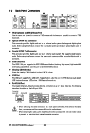
... cable, pull it side to side to a back panel connector, first remove the cable from your audio system provides an optical digital audio in connector. GA-EX58-EXTREME Motherboard - 24 - Clearing CMOS Switch Press the clearing CMOS switch to connect a PS/2 keyboard. Use this port for USB devices such as an USB keyboard/mouse...
... cable, pull it side to side to a back panel connector, first remove the cable from your audio system provides an optical digital audio in connector. GA-EX58-EXTREME Motherboard - 24 - Clearing CMOS Switch Press the clearing CMOS switch to connect a PS/2 keyboard. Use this port for USB devices such as an USB keyboard/mouse...


