Manual
Page 1
GA-EP45T-DS3R/ GA-EP45T-DS3 LGA775 socket motherboard for Intel® CoreTM processor family/ Intel® Pentium® processor family/Intel® Celeron® processor family User's Manual Rev. 1001 12ME-EP45TDS3R-1001R
GA-EP45T-DS3R/ GA-EP45T-DS3 LGA775 socket motherboard for Intel® CoreTM processor family/ Intel® Pentium® processor family/Intel® Celeron® processor family User's Manual Rev. 1001 12ME-EP45TDS3R-1001R
Manual
Page 2
Motherboard GA-EP45T-DS3R/GA-EP45T-DS3R Jun. 20, 2008 Motherboard GA-EP45T-DS3R/ GA-EP45T-DS3 Jun. 20, 2008
Motherboard GA-EP45T-DS3R/GA-EP45T-DS3R Jun. 20, 2008 Motherboard GA-EP45T-DS3R/ GA-EP45T-DS3 Jun. 20, 2008
Manual
Page 4
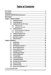
Table of Contents Box Contents ...6 OptionalItems ...6 GA-EP45T-DS3R/DS3 Motherboard Layout 7 Block Diagram ...8 Chapter 1 Hardware Installation 9 1-1 Installation Precautions 9 1-2 Product Specifications 10 1-3 Installing the CPU and CPU Cooler 13 1-3-1 Installing the CPU 13 1-3-2 Installing the CPU ... 59 2-12 Set Supervisor/User Password 60 2-13 Save & Exit Setup 61 2-14 Exit Without Saving 61 2-15 Security Chip Configuration (Note 62 Only for GA-EP45T-DS3R. - 4 -
Table of Contents Box Contents ...6 OptionalItems ...6 GA-EP45T-DS3R/DS3 Motherboard Layout 7 Block Diagram ...8 Chapter 1 Hardware Installation 9 1-1 Installation Precautions 9 1-2 Product Specifications 10 1-3 Installing the CPU and CPU Cooler 13 1-3-1 Installing the CPU 13 1-3-2 Installing the CPU ... 59 2-12 Set Supervisor/User Password 60 2-13 Save & Exit Setup 61 2-14 Exit Without Saving 61 2-15 Security Chip Configuration (Note 62 Only for GA-EP45T-DS3R. - 4 -
Manual
Page 6
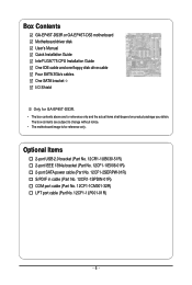
The box contents are for reference only. Box Contents GA-EP45T-DS3R or GA-EP45T-DS3 motherboard Motherboard driver disk User's Manual Quick Installation Guide Intel® LGA775 CPU Installation Guide One IDE cable and one floppy disk drive cable Four SATA 3Gb/s cables One SATA bracket I/O Shield Only for GA-EP45T-DS3R. • The box contents above are subject to change...
The box contents are for reference only. Box Contents GA-EP45T-DS3R or GA-EP45T-DS3 motherboard Motherboard driver disk User's Manual Quick Installation Guide Intel® LGA775 CPU Installation Guide One IDE cable and one floppy disk drive cable Four SATA 3Gb/s cables One SATA bracket I/O Shield Only for GA-EP45T-DS3R. • The box contents above are subject to change...
Manual
Page 7
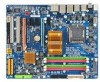
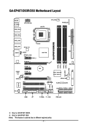
GA-EP45T-DS3R/DS3 Motherboard Layout KB_MS R_SPDIF ATX_12V_2X4 USB_1394_2 USB_1394_1 USB_LAN2 LGA775 CPU_FAN PHASE LED ATX GA-EP45T-DS3R/DS3 USB_LAN1 RTL8111C FDD AUDIO F_AUDIO Intel® P45 SYS_FAN1 PCIEX1_1 RTL8111C PCIEX16_1 PCIEX1_2 CODEC PCIEX1_3 SPDIF_I SPDIF_O PCIEX8_1 PCI1 DDR3_1 DDR3_2 DDR3_3 ... TPM IC (Note) F_USB2 F_USB1 IT8718 PCI2 CD_IN CI SATA2_4 SATA2_2 SATA2_0 SATA2_5 SATA2_3 SATA2_1 COMA LPT F_PANEL F1_1394 PWR_LED Only for GA-EP45T-DS3. (Note) This feature is optional due to different regional policy. - 7 - Only for GA-EP45T-DS3R.
GA-EP45T-DS3R/DS3 Motherboard Layout KB_MS R_SPDIF ATX_12V_2X4 USB_1394_2 USB_1394_1 USB_LAN2 LGA775 CPU_FAN PHASE LED ATX GA-EP45T-DS3R/DS3 USB_LAN1 RTL8111C FDD AUDIO F_AUDIO Intel® P45 SYS_FAN1 PCIEX1_1 RTL8111C PCIEX16_1 PCIEX1_2 CODEC PCIEX1_3 SPDIF_I SPDIF_O PCIEX8_1 PCI1 DDR3_1 DDR3_2 DDR3_3 ... TPM IC (Note) F_USB2 F_USB1 IT8718 PCI2 CD_IN CI SATA2_4 SATA2_2 SATA2_0 SATA2_5 SATA2_3 SATA2_1 COMA LPT F_PANEL F1_1394 PWR_LED Only for GA-EP45T-DS3. (Note) This feature is optional due to different regional policy. - 7 - Only for GA-EP45T-DS3R.
Manual
Page 10
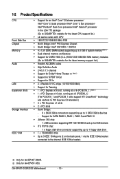
... devices iTE IT8718 chip: - 1 x floppy disk drive connector supporting up to 6 SATA 3Gb/s devices - Only for GA-EP45T-DS3R. GA-EP45T-DS3R/DS3 Motherboard - 10 - 1-2 Product Specifications CPU Front Side Bus Chipset Memory Audio LAN Expansion Slots Storage Interface IEEE 1394 Support for ... 1) Dual channel memory architecture Support for DDR3 1900 (O.C.)/1600/1333/1066/800 MHz memory modules (Go to GIGABYTE's website for the latest memory support list.) Realtek ALC889A codec High Definition Audio 2/4/5.1/7.1-channel ...
... devices iTE IT8718 chip: - 1 x floppy disk drive connector supporting up to 6 SATA 3Gb/s devices - Only for GA-EP45T-DS3R. GA-EP45T-DS3R/DS3 Motherboard - 10 - 1-2 Product Specifications CPU Front Side Bus Chipset Memory Audio LAN Expansion Slots Storage Interface IEEE 1394 Support for ... 1) Dual channel memory architecture Support for DDR3 1900 (O.C.)/1600/1333/1066/800 MHz memory modules (Go to GIGABYTE's website for the latest memory support list.) Realtek ALC889A codec High Definition Audio 2/4/5.1/7.1-channel ...
Manual
Page 12
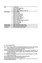
GA-EP45T-DS3R/DS3 Motherboard - 12 - When two graphics cards are installing one PCI Express graphics card, be less than 4 GB of physical memory is optional due to install it ... Factor; 30.5cm x 24.4cm Only for GA-EP45T-DS3R. (Note 1) Due to Windows Vista/XP 32-bit operating system limitation, when more than 4 GB. (Note 2) For Windows Vista/XP 32-bit operating system only. (Note 3) If you install. (Note 5) Available functions in EasyTune may differ by motherboard model. (Note 6) This feature is installed...
GA-EP45T-DS3R/DS3 Motherboard - 12 - When two graphics cards are installing one PCI Express graphics card, be less than 4 GB of physical memory is optional due to install it ... Factor; 30.5cm x 24.4cm Only for GA-EP45T-DS3R. (Note 1) Due to Windows Vista/XP 32-bit operating system limitation, when more than 4 GB. (Note 2) For Windows Vista/XP 32-bit operating system only. (Note 3) If you install. (Note 5) Available functions in EasyTune may differ by motherboard model. (Note 6) This feature is installed...

Manual
Page 14
... your thumb and index fingers. Step 5: Once the CPU is properly inserted, replace the load plate and push the CPU socket lever back into the motherboard CPU socket. Step 3: Lift the metal load plate on the CPU socket. Step 4: Hold the CPU with the socket alignment keys) and gently insert the... correctly install the CPU into its locked position. Follow the steps below to the CPU. B. CPU Socket Lever Step 1: Completely raise the CPU socket lever. GA-EP45T-DS3R/DS3 Motherboard - 14 -
... your thumb and index fingers. Step 5: Once the CPU is properly inserted, replace the load plate and push the CPU socket lever back into the motherboard CPU socket. Step 3: Lift the metal load plate on the CPU socket. Step 4: Hold the CPU with the socket alignment keys) and gently insert the... correctly install the CPU into its locked position. Follow the steps below to the CPU. B. CPU Socket Lever Step 1: Completely raise the CPU socket lever. GA-EP45T-DS3R/DS3 Motherboard - 14 -

Manual
Page 16
..., DDR3_4 Dual Channel Memory Configurations Table DDR3_1 DDR3_2 DDR3_3 DDR3_4 Two Modules DS/SS - - GA-EP45T-DS3R/DS3 Motherboard - 16 - Intel® Flex Memory Technology offers greater flexibility to upgrade by allowing different memory sizes to be used . (Go to GIGABYTE's website for optimum performance. • Each channel can be installed in Flex Memory Mode will...
..., DDR3_4 Dual Channel Memory Configurations Table DDR3_1 DDR3_2 DDR3_3 DDR3_4 Two Modules DS/SS - - GA-EP45T-DS3R/DS3 Motherboard - 16 - Intel® Flex Memory Technology offers greater flexibility to upgrade by allowing different memory sizes to be used . (Go to GIGABYTE's website for optimum performance. • Each channel can be installed in Flex Memory Mode will...

Manual
Page 18
...off the computer and unplug the power cord from the power outlet before you begin to install an expansion card: • Make sure the motherboard supports the expansion card. Make sure the card is securely seated in the slot. 3. Remove the metal slot cover from the slot. ...hardware damage. Locate an expansion slot that came with the slot, and press down on your card. Install the driver provided with a screw. 5. GA-EP45T-DS3R/DS3 Motherboard - 18 - • Removing the Card from the PCIEX8_1 slot: Press the white latch at the end of the card until it is fully seated...
...off the computer and unplug the power cord from the power outlet before you begin to install an expansion card: • Make sure the motherboard supports the expansion card. Make sure the card is securely seated in the slot. 3. Remove the metal slot cover from the slot. ...hardware damage. Locate an expansion slot that came with the slot, and press down on your card. Install the driver provided with a screw. 5. GA-EP45T-DS3R/DS3 Motherboard - 18 - • Removing the Card from the PCIEX8_1 slot: Press the white latch at the end of the card until it is fully seated...
Manual
Page 19
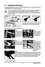
... the power switch on your motherboard. Connect the other ends of the external enclosure. Before connecting the SATA signal cable, make sure to turn off your SATA device. Follow the steps below to install the SATA bracket: Step 1: Locate one SATA power cable. Hardware Installation Only for GA-EP45T-DS3R. - 19 - SATA Bracket SATA...
... the power switch on your motherboard. Connect the other ends of the external enclosure. Before connecting the SATA signal cable, make sure to turn off your SATA device. Follow the steps below to install the SATA bracket: Step 1: Locate one SATA power cable. Hardware Installation Only for GA-EP45T-DS3R. - 19 - SATA Bracket SATA...

Manual
Page 20
... the LAN port LEDs. Use this feature, ensure that your audio system provides a coaxial digital audio in connector. GA-EP45T-DS3R/DS3 Motherboard - 20 - Use this feature, ensure that your device and then remove it from the motherboard. • When removing the cable, pull it side to side to an external audio system that supports digital...
... the LAN port LEDs. Use this feature, ensure that your audio system provides a coaxial digital audio in connector. GA-EP45T-DS3R/DS3 Motherboard - 20 - Use this feature, ensure that your device and then remove it from the motherboard. • When removing the cable, pull it side to side to an external audio system that supports digital...

Manual
Page 22
...) F1_1394 18) LPT 19) COMA 20) CI 21) CLR_CMOS 22) PHASE LED Read the following guidelines before turning on the computer, make sure your computer. GA-EP45T-DS3R/DS3 Motherboard - 22 - Unplug the power cord from the power outlet to prevent damage to the devices. • After installing the device and before connecting external devices... devices and your devices are compliant with the connectors you wish to connect. • Before installing the devices, be sure to the connector on the motherboard.
...) F1_1394 18) LPT 19) COMA 20) CI 21) CLR_CMOS 22) PHASE LED Read the following guidelines before turning on the computer, make sure your computer. GA-EP45T-DS3R/DS3 Motherboard - 22 - Unplug the power cord from the power outlet to prevent damage to the devices. • After installing the device and before connecting external devices... devices and your devices are compliant with the connectors you wish to connect. • Before installing the devices, be sure to the connector on the motherboard.

Manual
Page 24
...positive connection and requires a +12V voltage. For optimum heat dissipation, it in damage to locate pin 1 of different color. 34 33 GA-EP45T-DS3R/DS3 Motherboard 2 1 - 24 - The black connector wire is typically designated by a stripe of the connector and the floppy disk drive cable. ...The pin 1 of floppy disk drives supported are not configuration jumper blocks. 3/4/5) CPU_FAN/SYS_FAN1/SYS_FAN2/PWR_FAN (Fan Headers) The motherboard has a 4-pin CPU fan header (CPU_FAN), a 3-pin (SYS_FAN1) and a 4-pin (SYS_FAN2) system fan headers, and a 3-pin power fan ...
...positive connection and requires a +12V voltage. For optimum heat dissipation, it in damage to locate pin 1 of different color. 34 33 GA-EP45T-DS3R/DS3 Motherboard 2 1 - 24 - The black connector wire is typically designated by a stripe of the connector and the floppy disk drive cable. ...The pin 1 of floppy disk drives supported are not configuration jumper blocks. 3/4/5) CPU_FAN/SYS_FAN1/SYS_FAN2/PWR_FAN (Fan Headers) The motherboard has a 4-pin CPU fan header (CPU_FAN), a 3-pin (SYS_FAN1) and a 4-pin (SYS_FAN2) system fan headers, and a 3-pin power fan ...

Manual
Page 26
... in S3/S4 sleep state or powered off when the system is operating. Refer to Chapter 5, "Configuring SATA Hard Drive(s)," for GA-EP45T-DS3R. 8) SATA2_0/1/2/3/4/5 (SATA 3Gb/s Connectors) The SATA connectors conform to SATA 3Gb/s standard and are to be used, the total ...is on configuring a RAID array. Each SATA connector supports a single SATA device. If more than two hard drives are compatible with SATA 1.5Gb/s standard. GA-EP45T-DS3R/DS3 Motherboard - 26 - The ICH10R controller supports RAID 0, RAID 1, RAID 5 and RAID 10. The LED is off (S5). Pin No. 1 2 3 ...
... in S3/S4 sleep state or powered off when the system is operating. Refer to Chapter 5, "Configuring SATA Hard Drive(s)," for GA-EP45T-DS3R. 8) SATA2_0/1/2/3/4/5 (SATA 3Gb/s Connectors) The SATA connectors conform to SATA 3Gb/s standard and are to be used, the total ...is on configuring a RAID array. Each SATA connector supports a single SATA device. If more than two hard drives are compatible with SATA 1.5Gb/s standard. GA-EP45T-DS3R/DS3 Motherboard - 26 - The ICH10R controller supports RAID 0, RAID 1, RAID 5 and RAID 10. The LED is off (S5). Pin No. 1 2 3 ...

Manual
Page 28
... will make the device unable to the header. Definition 1 CD-L 2 GND 3 GND 4 CD-R 1 GA-EP45T-DS3R/DS3 Motherboard - 28 - 11) F_AUDIO (Front Panel Audio Header) The front panel audio header supports Intel High Definition audio (HD) and AC'97 audio. Definition 1 2 1 MIC2_L 2... chassis provide a front panel audio module that came with your chassis front panel audio module to the instructions on each wire instead of the motherboard header. Definition Pin No. If your chassis provides an AC'97 front panel audio module, refer to this header. Make sure the wire assignments...
... will make the device unable to the header. Definition 1 CD-L 2 GND 3 GND 4 CD-R 1 GA-EP45T-DS3R/DS3 Motherboard - 28 - 11) F_AUDIO (Front Panel Audio Header) The front panel audio header supports Intel High Definition audio (HD) and AC'97 audio. Definition 1 2 1 MIC2_L 2... chassis provide a front panel audio module that came with your chassis front panel audio module to the instructions on each wire instead of the motherboard header. Definition Pin No. If your chassis provides an AC'97 front panel audio module, refer to this header. Make sure the wire assignments...

Manual
Page 30
... power cord from the power outlet to prevent damage to the USB bracket. 16) F1_1394 (IEEE 1394a Header, Gray) The header conforms to USB 2.0/1.1 specification. GA-EP45T-DS3R/DS3 Motherboard - 30 - For purchasing the optional IEEE 1394a bracket, please contact the local dealer. 9 1 10 2 Pin No. 1 2 3 4 5 6 7 8 9 10 Definition TPA+ TPAGND GND TPB+ TPBPower (12V) Power...
... power cord from the power outlet to prevent damage to the USB bracket. 16) F1_1394 (IEEE 1394a Header, Gray) The header conforms to USB 2.0/1.1 specification. GA-EP45T-DS3R/DS3 Motherboard - 30 - For purchasing the optional IEEE 1394a bracket, please contact the local dealer. 9 1 10 2 Pin No. 1 2 3 4 5 6 7 8 9 10 Definition TPA+ TPAGND GND TPB+ TPBPower (12V) Power...

Manual
Page 32
... temporarily short the two pins or use a metal object like a screwdriver to factory defaults. Failure to do so may cause damage to the motherboard. • After system restart, go to BIOS Setup to load factory defaults (select Load Optimized Defaults) or manually configure the BIOS settings (... clear the CMOS values (e.g. This function requires a chassis with chassis intrusion detection design. Pin No. 19) CI (Chassis Intrusion Header) This motherboard provides a chassis detection feature that detects if the chassis cover has been removed. GA-EP45T-DS3R/DS3 Motherboard - 32 -
... temporarily short the two pins or use a metal object like a screwdriver to factory defaults. Failure to do so may cause damage to the motherboard. • After system restart, go to BIOS Setup to load factory defaults (select Load Optimized Defaults) or manually configure the BIOS settings (... clear the CMOS values (e.g. This function requires a chassis with chassis intrusion detection design. Pin No. 19) CI (Chassis Intrusion Header) This motherboard provides a chassis detection feature that detects if the chassis cover has been removed. GA-EP45T-DS3R/DS3 Motherboard - 32 -

Manual
Page 34
GA-EP45T-DS3R/DS3 Motherboard - 34 -
GA-EP45T-DS3R/DS3 Motherboard - 34 -

Manual
Page 36
... from the device configured in Boot Menu is effective for subsequent access to XpressRecovery2 during the POST. GA-EP45T-DS3R/DS3 Motherboard - 36 - The LOGO Screen (Default) :POST Screen :BIOS Setup/Q-Flash :XpressRecovery2 :Boot Menu :Qflash B. Motherboard Model BIOS Version EP45T-DS3R E6 . . . . : BIOS Setup : XpressRecovery2 : Boot Menu : Qflash 05/28/2008-P45-ICH10-7A89PG0LC-00 Function Keys...
... from the device configured in Boot Menu is effective for subsequent access to XpressRecovery2 during the POST. GA-EP45T-DS3R/DS3 Motherboard - 36 - The LOGO Screen (Default) :POST Screen :BIOS Setup/Q-Flash :XpressRecovery2 :Boot Menu :Qflash B. Motherboard Model BIOS Version EP45T-DS3R E6 . . . . : BIOS Setup : XpressRecovery2 : Boot Menu : Qflash 05/28/2008-P45-ICH10-7A89PG0LC-00 Function Keys...


