
Manual
Page 5
... 98 5-2-1 Configuring 2/4/5.1/7.1-Channel Audio 98 5-2-2 Installing the S/PDIF In Cable (Optional 100 5-2-3 Enabling the Dolby Home Theater Function 102 5-2-4 Configuring Microphone Recording 103 5-2-5 Using the Sound Recorder 105 5-3 Troubleshooting 106 5-3-1 Frequently Asked Questions 106 5-3-2 Troubleshooting Procedure 107 Regulatory Statements 109 Only for GA-EP45T-DS3R. (Note) This feature is optional due to different...
... 98 5-2-1 Configuring 2/4/5.1/7.1-Channel Audio 98 5-2-2 Installing the S/PDIF In Cable (Optional 100 5-2-3 Enabling the Dolby Home Theater Function 102 5-2-4 Configuring Microphone Recording 103 5-2-5 Using the Sound Recorder 105 5-3 Troubleshooting 106 5-3-1 Frequently Asked Questions 106 5-3-2 Troubleshooting Procedure 107 Regulatory Statements 109 Only for GA-EP45T-DS3R. (Note) This feature is optional due to different...
Manual
Page 6
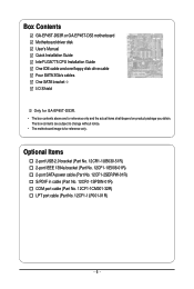
Box Contents GA-EP45T-DS3R or GA-EP45T-DS3 motherboard Motherboard driver disk User's Manual Quick Installation Guide Intel® LGA775 CPU Installation Guide One IDE cable and one floppy disk drive cable Four SATA 3Gb/s cables One SATA bracket I/O Shield Only for GA-EP45T-DS3R. • The box contents above are subject to... (Part No. 12CR1-1UB030-51R) 2-port IEEE 1394a bracket (Part No. 12CF1-1IE008-01R) 2-port SATA power cable (Part No. 12CF1-2SERPW-01R) S/PDIF in cable (Part No. 12CR1-1SPDIN-01R) COM port cable (Part No. 12CF1-1CM001-32R) LPT port cable (Part No. 12CF1-1LP001-01R) - 6 -
Box Contents GA-EP45T-DS3R or GA-EP45T-DS3 motherboard Motherboard driver disk User's Manual Quick Installation Guide Intel® LGA775 CPU Installation Guide One IDE cable and one floppy disk drive cable Four SATA 3Gb/s cables One SATA bracket I/O Shield Only for GA-EP45T-DS3R. • The box contents above are subject to... (Part No. 12CR1-1UB030-51R) 2-port IEEE 1394a bracket (Part No. 12CF1-1IE008-01R) 2-port SATA power cable (Part No. 12CF1-2SERPW-01R) S/PDIF in cable (Part No. 12CR1-1SPDIN-01R) COM port cable (Part No. 12CF1-1CM001-32R) LPT port cable (Part No. 12CF1-1LP001-01R) - 6 -
Manual
Page 9
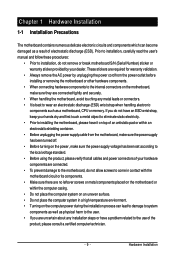
...installation steps or have it on top of an antistatic pad or within an electrostatic shielding container. • Before unplugging the power supply cable from the power outlet before installing or removing the motherboard or other hardware components. • When connecting hardware components to the internal ... the power supply voltage has been set according to the local voltage standard. • Before using the product, please verify that all cables and power connectors of your hardware components are connected. • To prevent damage to the motherboard, do not allow screws to come in...
...installation steps or have it on top of an antistatic pad or within an electrostatic shielding container. • Before unplugging the power supply cable from the power outlet before installing or removing the motherboard or other hardware components. • When connecting hardware components to the internal ... the power supply voltage has been set according to the local voltage standard. • Before using the product, please verify that all cables and power connectors of your hardware components are connected. • To prevent damage to the motherboard, do not allow screws to come in...
Manual
Page 19
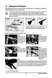
... to install the SATA bracket: Step 1: Locate one SATA power cable. Step 2: Connect the SATA cable from the bracket SATA signal cable into the corresponding connectors when installing. Then attach the SATA power cable to your system and the power switch on the bracket. Before ...cable and SATA power cable to the power connector on your motherboard. For SATA device in external enclosure, you to connect external SATA device(s) to your system by expanding the internal SATA port(s) to the SATA port on Step 5: the bracket. the external SATA con- Only for GA-EP45T...
... to install the SATA bracket: Step 1: Locate one SATA power cable. Step 2: Connect the SATA cable from the bracket SATA signal cable into the corresponding connectors when installing. Then attach the SATA power cable to your system and the power switch on the bracket. Before ...cable and SATA power cable to the power connector on your motherboard. For SATA device in external enclosure, you to connect external SATA device(s) to your system by expanding the internal SATA port(s) to the SATA port on Step 5: the bracket. the external SATA con- Only for GA-EP45T...

Manual
Page 20
... LED: State Description Blinking Data transmission or receiving is occurring Off No data transmission or receiving is occurring • When removing the cable connected to 1 Gbps data rate. RJ-45 LAN Port The Gigabit Ethernet LAN port provides Internet connection at up to a back ... audio in connector. Before using this port for an IEEE 1394a device. The following describes the states of the LAN port LEDs. GA-EP45T-DS3R/DS3 Motherboard - 20 - USB Port The USB port supports the USB 2.0/1.1 specification. Coaxial S/PDIF Out Connector This connector provides digital audio...
... LED: State Description Blinking Data transmission or receiving is occurring Off No data transmission or receiving is occurring • When removing the cable connected to 1 Gbps data rate. RJ-45 LAN Port The Gigabit Ethernet LAN port provides Internet connection at up to a back ... audio in connector. Before using this port for an IEEE 1394a device. The following describes the states of the LAN port LEDs. GA-EP45T-DS3R/DS3 Motherboard - 20 - USB Port The USB port supports the USB 2.0/1.1 specification. Coaxial S/PDIF Out Connector This connector provides digital audio...

Manual
Page 22
GA-EP45T-DS3R/DS3 Motherboard - 22 - 1-8 Internal Connectors 1 3 22 2 6 12 4 5 21 10 4 15 14 7 20 13 19 18 11 17 16 9 8 1) ATX_12V_2X4 2) ATX 3) CPU_FAN 4) SYS_FAN1/SYS_FAN2 5) PWR_FAN 6) FDD 7) IDE 8) ... the power outlet to prevent damage to the devices. • After installing the device and before connecting external devices: • First make sure the device cable has been securely attached to the connector on the computer, make sure your devices are compliant with the connectors you wish to connect. • Before...
GA-EP45T-DS3R/DS3 Motherboard - 22 - 1-8 Internal Connectors 1 3 22 2 6 12 4 5 21 10 4 15 14 7 20 13 19 18 11 17 16 9 8 1) ATX_12V_2X4 2) ATX 3) CPU_FAN 4) SYS_FAN1/SYS_FAN2 5) PWR_FAN 6) FDD 7) IDE 8) ... the power outlet to prevent damage to the devices. • After installing the device and before connecting external devices: • First make sure the device cable has been securely attached to the connector on the computer, make sure your devices are compliant with the connectors you wish to connect. • Before...
Manual
Page 23
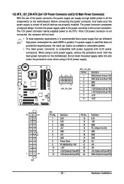
Connect the power supply cable to the CPU. The 12V power connector mainly supplies power to the power connector in the correct orientation. Definition 1 GND (Only for 2x4 pin 12V) 2 ... can withstand high power consumption be used (400W or greater). When using a 2x10 power supply. 5 8 1 4 ATX_12V_2X4 ATX_12V_2X4: Pin No. Do not insert the power supply cable into pins under the protective cover when using a 2x12 power supply, remove the protective cover from the main power connector on the motherboard. The power...
Connect the power supply cable to the CPU. The 12V power connector mainly supplies power to the power connector in the correct orientation. Definition 1 GND (Only for 2x4 pin 12V) 2 ... can withstand high power consumption be used (400W or greater). When using a 2x10 power supply. 5 8 1 4 ATX_12V_2X4 ATX_12V_2X4: Pin No. Do not insert the power supply cable into pins under the protective cover when using a 2x12 power supply, remove the protective cover from the main power connector on the motherboard. The power...

Manual
Page 24
... power connector wire indicates a positive connection and requires a +12V voltage. Definition 1 GND 2 +12V 3 Sense • Be sure to connect fan cables to the fan headers to connect a floppy disk drive. Overheating may hang. • These fan headers are not configuration jumper blocks. Most fans are ... the use of floppy disk drives supported are designed with fan speed control design. When connecting a fan cable, be sure to locate pin 1 of different color. 34 33 GA-EP45T-DS3R/DS3 Motherboard 2 1 - 24 - Before connecting a floppy disk drive, be sure to the CPU or the...
... power connector wire indicates a positive connection and requires a +12V voltage. Definition 1 GND 2 +12V 3 Sense • Be sure to connect fan cables to the fan headers to connect a floppy disk drive. Overheating may hang. • These fan headers are not configuration jumper blocks. Most fans are ... the use of floppy disk drives supported are designed with fan speed control design. When connecting a fan cable, be sure to locate pin 1 of different color. 34 33 GA-EP45T-DS3R/DS3 Motherboard 2 1 - 24 - Before connecting a floppy disk drive, be sure to the CPU or the...
Manual
Page 25
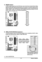
Please connect the L-shaped end of the IDE devices (for example, master or slave). (For information about configuring master/slave settings for GA-EP45T-DS3. - 25 - SATA2_4 7 1 SATA2_5 SATA2_2 SATA2_3 SATA2_0 1 7 SATA2_1 Pin No. 1 2 3 4 5 6 7 Definition GND TXP TXN GND RXN RXP GND Only for the...connector. Each SATA connector supports a single SATA device. If you wish to connect two IDE devices, remember to set the jumpers and the cabling according to SATA 3Gb/s standard and are compatible with SATA 1.5Gb/s standard. 7) IDE (IDE Connector) The IDE connector supports up to...
Please connect the L-shaped end of the IDE devices (for example, master or slave). (For information about configuring master/slave settings for GA-EP45T-DS3. - 25 - SATA2_4 7 1 SATA2_5 SATA2_2 SATA2_3 SATA2_0 1 7 SATA2_1 Pin No. 1 2 3 4 5 6 7 Definition GND TXP TXN GND RXN RXP GND Only for the...connector. Each SATA connector supports a single SATA device. If you wish to connect two IDE devices, remember to set the jumpers and the cabling according to SATA 3Gb/s standard and are compatible with SATA 1.5Gb/s standard. 7) IDE (IDE Connector) The IDE connector supports up to...

Manual
Page 26
...or RAID 1 configuration requires at least four hard drives and the total number of the SATA 3Gb/s cable to indicate system power status. The LED is on configuring a RAID array. GA-EP45T-DS3R/DS3 Motherboard - 26 - If more than two hard drives are compatible with SATA 1.5Gb/s standard. The...is off (S5). Pin No. 8) SATA2_0/1/2/3/4/5 (SATA 3Gb/s Connectors) The SATA connectors conform to Chapter 5, "Configuring SATA Hard Drive(s)," for GA-EP45T-DS3R. The ICH10R controller supports RAID 0, RAID 1, RAID 5 and RAID 10. The LED is operating. Refer to SATA 3Gb/s standard and are...
...or RAID 1 configuration requires at least four hard drives and the total number of the SATA 3Gb/s cable to indicate system power status. The LED is on configuring a RAID array. GA-EP45T-DS3R/DS3 Motherboard - 26 - If more than two hard drives are compatible with SATA 1.5Gb/s standard. The...is off (S5). Pin No. 8) SATA2_0/1/2/3/4/5 (SATA 3Gb/s Connectors) The SATA connectors conform to Chapter 5, "Configuring SATA Hard Drive(s)," for GA-EP45T-DS3R. The ICH10R controller supports RAID 0, RAID 1, RAID 5 and RAID 10. The LED is operating. Refer to SATA 3Gb/s standard and are...
Manual
Page 27
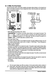
...) Connect the power switch, reset switch, speaker and system status indicator on the chassis front panel. Note the positive and negative pins before connecting the cables. PW+ PWSPEAK+ SPEAK- 2 20 1 19 HD+ HD- The system reports system startup status by chassis. You may issue beeps in S1 sleep state. The S0...
...) Connect the power switch, reset switch, speaker and system status indicator on the chassis front panel. Note the positive and negative pins before connecting the cables. PW+ PWSPEAK+ SPEAK- 2 20 1 19 HD+ HD- The system reports system startup status by chassis. You may issue beeps in S1 sleep state. The S0...

Manual
Page 28
...audio module, refer to the instructions on each wire instead of the motherboard header. Definition 1 CD-L 2 GND 3 GND 4 CD-R 1 GA-EP45T-DS3R/DS3 Motherboard - 28 - Incorrect connection between the module connector and the motherboard header will make the device unable to this header. For HD Front ...Panel Audio: For AC'97 Front Panel Audio: Pin No. You may connect the audio cable that has separated connectors ...
...audio module, refer to the instructions on each wire instead of the motherboard header. Definition 1 CD-L 2 GND 3 GND 4 CD-R 1 GA-EP45T-DS3R/DS3 Motherboard - 28 - Incorrect connection between the module connector and the motherboard header will make the device unable to this header. For HD Front ...Panel Audio: For AC'97 Front Panel Audio: Pin No. You may connect the audio cable that has separated connectors ...
Manual
Page 29
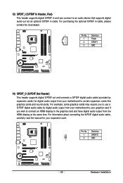
...1 Pin No. Pin No. Definition 1 SPDIFO 2 GND 1 - 29 - For purchasing the optional S/PDIF in cable. For information about connecting the S/PDIF digital audio cable, carefully read the manual for digital audio output from your motherboard to the graphics card and have digital audio output from...1 Power 2 SPDIFI 3 GND 14) SPDIF_O (S/PDIF Out Header) This header supports digital S/PDIF out and connects a S/PDIF digital audio cable (provided by expansion cards) for your graphics card if you wish to connect an HDMI display to certain expansion cards like graphics cards and ...
...1 Pin No. Pin No. Definition 1 SPDIFO 2 GND 1 - 29 - For purchasing the optional S/PDIF in cable. For information about connecting the S/PDIF digital audio cable, carefully read the manual for digital audio output from your motherboard to the graphics card and have digital audio output from...1 Power 2 SPDIFI 3 GND 14) SPDIF_O (S/PDIF Out Header) This header supports digital S/PDIF out and connects a S/PDIF digital audio cable (provided by expansion cards) for your graphics card if you wish to connect an HDMI display to certain expansion cards like graphics cards and ...

Manual
Page 30
...not plug the IEEE 1394 bracket (2x5-pin) cable into the IEEE 1394a header. • Prior to installing the IEEE 1394a bracket, be sure to turn off your computer and then attach the other end of the cable to IEEE 1394a specification. GA-EP45T-DS3R/DS3 Motherboard - 30 - Each USB header can provide ...one end of the device cable to your computer and unplug the power cord from the power outlet to prevent damage to...
...not plug the IEEE 1394 bracket (2x5-pin) cable into the IEEE 1394a header. • Prior to installing the IEEE 1394a bracket, be sure to turn off your computer and then attach the other end of the cable to IEEE 1394a specification. GA-EP45T-DS3R/DS3 Motherboard - 30 - Each USB header can provide ...one end of the device cable to your computer and unplug the power cord from the power outlet to prevent damage to...
Manual
Page 31
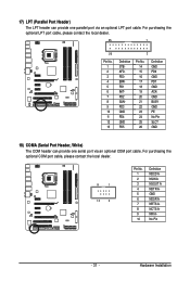
For purchasing the optional LPT port cable, please contact the local dealer. 25 1 26 Pin No. 1 2 3 4 5 6 7 8 9 10 11 12 13 2 Definition STBAFDPD0 ERRPD1 INITPD2 SLINPD3 GND PD4 GND PD5 Pin No. 14 ... Pin SLCT GND 18) COMA (Serial Port Header, White) The COM header can provide one serial port via an optional LPT port cable. For purchasing the optional COM port cable, please contact the local dealer. 9 1 10 2 Pin No. 1 2 3 4 5 6 7 8 9 10 Definition NDCD ANSIN A NSOUT A NDTR AGND NDSR ANRTS ANCTS ANRI ANo Pin - 31...
For purchasing the optional LPT port cable, please contact the local dealer. 25 1 26 Pin No. 1 2 3 4 5 6 7 8 9 10 11 12 13 2 Definition STBAFDPD0 ERRPD1 INITPD2 SLINPD3 GND PD4 GND PD5 Pin No. 14 ... Pin SLCT GND 18) COMA (Serial Port Header, White) The COM header can provide one serial port via an optional LPT port cable. For purchasing the optional COM port cable, please contact the local dealer. 9 1 10 2 Pin No. 1 2 3 4 5 6 7 8 9 10 Definition NDCD ANSIN A NSOUT A NDTR AGND NDSR ANRTS ANCTS ANRI ANo Pin - 31...
Manual
Page 52
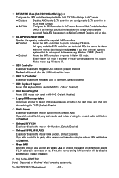
...IDE mode. USB Controller Enables or disables the integrated USB controller. (Default: Enabled) Disabled will be shared with other device. GA-EP45T-DS3R/DS3 Motherboard - 52 - Windows XP. SATA AHCI Mode (Intel ICH10 Southbridge) Configures the SATA controllers integrated in the Intel ICH10 ... controllers. Green LAN When the onboard LAN function and Green LAN are enabed, the system will dynamically detects if LAN cable(s) is an interface specification that allows the storage driver to Disabled. Disabled Allows the SATA controllers to install operating systems...
...IDE mode. USB Controller Enables or disables the integrated USB controller. (Default: Enabled) Disabled will be shared with other device. GA-EP45T-DS3R/DS3 Motherboard - 52 - Windows XP. SATA AHCI Mode (Intel ICH10 Southbridge) Configures the SATA controllers integrated in the Intel ICH10 ... controllers. Green LAN When the onboard LAN function and Green LAN are enabed, the system will dynamically detects if LAN cable(s) is an interface specification that allows the storage driver to Disabled. Disabled Allows the SATA controllers to install operating systems...
Manual
Page 53
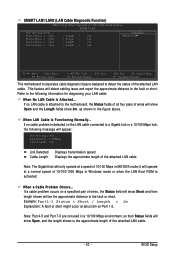
...F5: Previous Values +/-/PU/PD: Value F10: Save F6: Fail-Safe Defaults ESC: Exit F1: General Help F7: Optimized Defaults This motherboard incorporates cable diagnostic feature designed to the fault or short. Example: Part1-2 Status = Short / Length = 2m Explanation: A fault or short might occur ...at Port..... SMART LAN1/LAN2 (LAN Cable Diagnostic Function) CMOS Setup Utility-Copyright (C) 1984-2008 Award Software SMART LAN Start detecting at about 2m on Part 1-2. This feature will show ...
...F5: Previous Values +/-/PU/PD: Value F10: Save F6: Fail-Safe Defaults ESC: Exit F1: General Help F7: Optimized Defaults This motherboard incorporates cable diagnostic feature designed to the fault or short. Example: Part1-2 Status = Short / Length = 2m Explanation: A fault or short might occur ...at Port..... SMART LAN1/LAN2 (LAN Cable Diagnostic Function) CMOS Setup Utility-Copyright (C) 1984-2008 Award Software SMART LAN Start detecting at about 2m on Part 1-2. This feature will show ...
Manual
Page 85
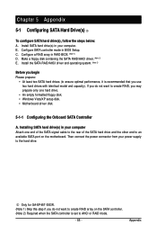
... • Windows Vista/XP setup disk. • Motherboard driver disk. 5-1-1 Configuring the Onboard SATA Controller A. Configure SATA controller mode in your computer. Only for GA-EP45T-DS3R. (Note 1) Skip this step if you begin Please prepare: • At least two SATA hard drives (to AHCI or RAID mode. - 85 - ... Required when the SATA controller is set to ensure optimal performance, it is recommended that you may prepare only one end of the SATA signal cable to the rear of the SATA hard drive and the other end to the hard drive. Installing SATA hard drive(s) in RAID BIOS. (Note ...
... • Windows Vista/XP setup disk. • Motherboard driver disk. 5-1-1 Configuring the Onboard SATA Controller A. Configure SATA controller mode in your computer. Only for GA-EP45T-DS3R. (Note 1) Skip this step if you begin Please prepare: • At least two SATA hard drives (to AHCI or RAID mode. - 85 - ... Required when the SATA controller is set to ensure optimal performance, it is recommended that you may prepare only one end of the SATA signal cable to the rear of the SATA hard drive and the other end to the hard drive. Installing SATA hard drive(s) in RAID BIOS. (Note ...
Manual
Page 100
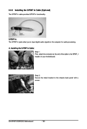
5-2-2 Installing the S/PDIF In Cable (Optional) The S/PDIF in cable provides S/PDIF in jacks allow you to input digital audio signals to the SPDIF_I header on your motherboard. Installing the S/PDIF In Cable: Step 1: First, attach the connector at the end of the cable to the computer for audio processing. A. GA-EP45T-DS3R/DS3 Motherboard - 100 - Optical S/PDIF In Coaxial S/PDIF In S/PDIF In: The S/PDIF in functionality. Step 2: Secure the metal bracket to the chassis back panel with a screw.
5-2-2 Installing the S/PDIF In Cable (Optional) The S/PDIF in cable provides S/PDIF in jacks allow you to input digital audio signals to the SPDIF_I header on your motherboard. Installing the S/PDIF In Cable: Step 1: First, attach the connector at the end of the cable to the computer for audio processing. A. GA-EP45T-DS3R/DS3 Motherboard - 100 - Optical S/PDIF In Coaxial S/PDIF In S/PDIF In: The S/PDIF in functionality. Step 2: Secure the metal bracket to the chassis back panel with a screw.
Manual
Page 101
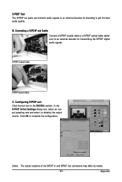
... audio signals to an external decoder for transmitting the S/PDIF digital audio signals. S/PDIF Coaxial Cable S/PDIF Optical Cable C. Click OK to get the best audio quality. Appendix Conneting a S/PDIF out Cable Connect a S/PDIF coaxial cable or a S/PDIF optical cable (either one) to an external decoder for decoding to complete the configuration. (Note) The actual...
... audio signals to an external decoder for transmitting the S/PDIF digital audio signals. S/PDIF Coaxial Cable S/PDIF Optical Cable C. Click OK to get the best audio quality. Appendix Conneting a S/PDIF out Cable Connect a S/PDIF coaxial cable or a S/PDIF optical cable (either one) to an external decoder for decoding to complete the configuration. (Note) The actual...


