Manual
Page 1
GA-EP45C-DS3R/ GA-EP45C-DS3 LGA775 socket motherboard for Intel® CoreTM processor family/ Intel® Pentium® processor family/Intel® Celeron® processor family User's Manual Rev. 1001 12ME-EP45CDS3R-1001R
GA-EP45C-DS3R/ GA-EP45C-DS3 LGA775 socket motherboard for Intel® CoreTM processor family/ Intel® Pentium® processor family/Intel® Celeron® processor family User's Manual Rev. 1001 12ME-EP45CDS3R-1001R

Manual
Page 2
Motherboard GA-EP45C-DS3R/GA-EP45C-DS3 May. 15, 2008 Motherboard GA-EP45C-DS3R/ GA-EP45C-DS3 May. 15, 2008
Motherboard GA-EP45C-DS3R/GA-EP45C-DS3 May. 15, 2008 Motherboard GA-EP45C-DS3R/ GA-EP45C-DS3 May. 15, 2008

Manual
Page 4
Table of Contents Box Contents ...6 OptionalItems...6 GA-EP45C-DS3R/DS3 Motherboard Layout 7 Block Diagram...8 Chapter 1 Hardware Installation 9 1-1 Installation Precautions 9 1-2 Product Specifications 10 1-3 Installing the CPU and CPU Cooler 13 1-3-1 Installing the CPU 13 1-3-2 Installing the ...
Table of Contents Box Contents ...6 OptionalItems...6 GA-EP45C-DS3R/DS3 Motherboard Layout 7 Block Diagram...8 Chapter 1 Hardware Installation 9 1-1 Installation Precautions 9 1-2 Product Specifications 10 1-3 Installing the CPU and CPU Cooler 13 1-3-1 Installing the CPU 13 1-3-2 Installing the ...
Manual
Page 6
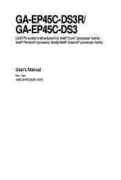
...01R) COM port cable (Part No. 12CF1-1CM001-32R) LPT port cable (Part No. 12CF1-1LP001-01R) - 6 - Box Contents GA-EP45C-DS3R or GA-EP45C-DS3 motherboard Motherboard driver disk User's Manual Quick Installation Guide One IDE cable and one floppy disk drive cable Four SATA 3Gb/s cables One SATA ...bracket I/O Shield Only for GA-EP45C-DS3R. • The box contents above are subject to change without notice. • The motherboard ...
...01R) COM port cable (Part No. 12CF1-1CM001-32R) LPT port cable (Part No. 12CF1-1LP001-01R) - 6 - Box Contents GA-EP45C-DS3R or GA-EP45C-DS3 motherboard Motherboard driver disk User's Manual Quick Installation Guide One IDE cable and one floppy disk drive cable Four SATA 3Gb/s cables One SATA ...bracket I/O Shield Only for GA-EP45C-DS3R. • The box contents above are subject to change without notice. • The motherboard ...

Manual
Page 7
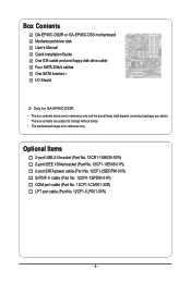
... KB_MS R_SPDIF ATX_12V_2X4 USB_1394_2 LGA775 USB_1394_1 USB_LAN2 CPU_FAN PHASE LED ATX GA-EP45C-DS3R/DS3 USB_LAN1 RTL8111C FDD AUDIO F_AUDIO Intel® P45 SYS_FAN1 PCIEX1_1 DDR2_3 DDR2_4 DDR3_2 DDR2_1 DDR2_2 DDR3_1 RTL8111C PCIEX16_1 PCIEX1_2 CODEC PCIEX1_3 SPDIF_I SPDIF_O PCIEX8_1 PCI1... M_BIOS B_BIOS TPM IC (Note) F_USB2 F_USB1 IT8718 PCI2 CD_IN CI SATA2_4 SATA2_2 SATA2_0 SATA2_5 SATA2_3 SATA2_1 COMA LPT F_PANEL F1_1394 PWR_LED Only for GA-EP45C-DS3. (Note) This feature is optional due to different regional policy. - 7 - Only for GA-EP45C-DS3R.
... KB_MS R_SPDIF ATX_12V_2X4 USB_1394_2 LGA775 USB_1394_1 USB_LAN2 CPU_FAN PHASE LED ATX GA-EP45C-DS3R/DS3 USB_LAN1 RTL8111C FDD AUDIO F_AUDIO Intel® P45 SYS_FAN1 PCIEX1_1 DDR2_3 DDR2_4 DDR3_2 DDR2_1 DDR2_2 DDR3_1 RTL8111C PCIEX16_1 PCIEX1_2 CODEC PCIEX1_3 SPDIF_I SPDIF_O PCIEX8_1 PCI1... M_BIOS B_BIOS TPM IC (Note) F_USB2 F_USB1 IT8718 PCI2 CD_IN CI SATA2_4 SATA2_2 SATA2_0 SATA2_5 SATA2_3 SATA2_1 COMA LPT F_PANEL F1_1394 PWR_LED Only for GA-EP45C-DS3. (Note) This feature is optional due to different regional policy. - 7 - Only for GA-EP45C-DS3R.

Manual
Page 8
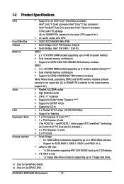
Only for GA-EP45C-DS3R. Block Diagram 1 PCI Express x16 1 PCI Express x8 PCIe CLK (100 MHz) PCIe CLK (100 MHz) PCI Express x16 PCI Express x8 LAN2 LAN1 3 PCI ... Speaker Out Center/Subwoofer Speaker Out Side Speaker Out MIC Line-Out Line-In SPDIF In SPDIF Out 2 PCI PCI CLK (33 MHz) Only for GA-EP45C-DS3. (Note) This feature is optional due to different regional policy. - 8 -
Only for GA-EP45C-DS3R. Block Diagram 1 PCI Express x16 1 PCI Express x8 PCIe CLK (100 MHz) PCIe CLK (100 MHz) PCI Express x16 PCI Express x8 LAN2 LAN1 3 PCI ... Speaker Out Center/Subwoofer Speaker Out Side Speaker Out MIC Line-Out Line-In SPDIF In SPDIF Out 2 PCI PCI CLK (33 MHz) Only for GA-EP45C-DS3. (Note) This feature is optional due to different regional policy. - 8 -
Manual
Page 10
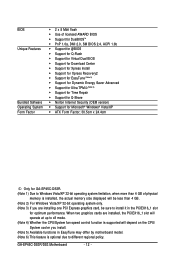
.../13331066/800 MHz memory modules DDR2: Š 4 x 1.8V DDR2 DIMM sockets supporting up to 6 SATA 3Gb/s devices - Go to GIGABYTE's website for the latest memory support list.) Š Realtek ALC889A codec Š High Definition Audio Š 2/4/5.1/7.1-channel Š Support for ...floppy disk drive connector supporting up to 16 GB of system memory(Note 1) Š Dual channel memory architecture Š Support for GA-EP45C-DS3. GA-EP45C-DS3R/DS3 Motherboard - 10 - Only for DDR2 1066/800/667 MHz memory modules (Note: Mixed mode, populating DDR2 and DDR3 memory modules simultaneously is...
.../13331066/800 MHz memory modules DDR2: Š 4 x 1.8V DDR2 DIMM sockets supporting up to 6 SATA 3Gb/s devices - Go to GIGABYTE's website for the latest memory support list.) Š Realtek ALC889A codec Š High Definition Audio Š 2/4/5.1/7.1-channel Š Support for ...floppy disk drive connector supporting up to 16 GB of system memory(Note 1) Š Dual channel memory architecture Š Support for GA-EP45C-DS3. GA-EP45C-DS3R/DS3 Motherboard - 10 - Only for DDR2 1066/800/667 MHz memory modules (Note: Mixed mode, populating DDR2 and DDR3 memory modules simultaneously is...
Manual
Page 12
... Š Norton Internet Security (OEM version) Š Support for Microsoft® Windows® Vista/XP Š ATX Form Factor; 30.5cm x 24.4cm Only for GA-EP45C-DS3R. (Note 1) Due to Windows Vista/XP 32-bit operating system limitation, when more than 4 GB. (Note 2) For Windows Vista/XP 32-bit operating system only...
... Š Norton Internet Security (OEM version) Š Support for Microsoft® Windows® Vista/XP Š ATX Form Factor; 30.5cm x 24.4cm Only for GA-EP45C-DS3R. (Note 1) Due to Windows Vista/XP 32-bit operating system limitation, when more than 4 GB. (Note 2) For Windows Vista/XP 32-bit operating system only...
Manual
Page 14
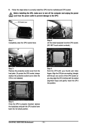
... install the CPU into the motherboard CPU socket. Follow the steps below to the CPU. CPU Socket Lever Step 1: Completely raise the CPU socket lever. GA-EP45C-DS3R/DS3 Motherboard - 14 - Before installing the CPU, make sure to turn off the computer and unplug the power cord from the load plate. (To protect the...
... install the CPU into the motherboard CPU socket. Follow the steps below to the CPU. CPU Socket Lever Step 1: Completely raise the CPU socket lever. GA-EP45C-DS3R/DS3 Motherboard - 14 - Before installing the CPU, make sure to turn off the computer and unplug the power cord from the load plate. (To protect the...
Manual
Page 16
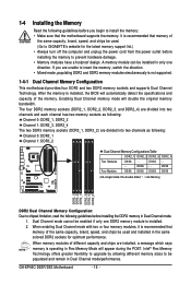
... DS/SS - - DS/SS - - 1-4 Installing the Memory Read the following guidelines before you are unable to GIGABYTE's website for optimum performance. If you begin to be populated and remain in Dual Channel mode/performance. GA-EP45C-DS3R/DS3 Motherboard - 16 - When enabling Dual Channel mode with two or four memory modules, it is recommended that...
... DS/SS - - DS/SS - - 1-4 Installing the Memory Read the following guidelines before you are unable to GIGABYTE's website for optimum performance. If you begin to be populated and remain in Dual Channel mode/performance. GA-EP45C-DS3R/DS3 Motherboard - 16 - When enabling Dual Channel mode with two or four memory modules, it is recommended that...
Manual
Page 18
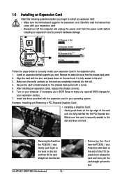
... expansion card. • Always turn off the computer and unplug the power cord from the slot. After installing all expansion cards, replace the chassis cover(s). 6. GA-EP45C-DS3R/DS3 Motherboard - 18 - • Removing the Card from the PCIEX8_1 slot: Press the white latch at the end of the card until it is fully seated...
... expansion card. • Always turn off the computer and unplug the power cord from the slot. After installing all expansion cards, replace the chassis cover(s). 6. GA-EP45C-DS3R/DS3 Motherboard - 18 - • Removing the Card from the PCIEX8_1 slot: Press the white latch at the end of the card until it is fully seated...

Manual
Page 20
... The USB port supports the USB 2.0/1.1 specification. Use this feature, ensure that supports digital coaxial audio. Before using this port for an IEEE 1394a device. GA-EP45C-DS3R/DS3 Motherboard - 20 - 1-7 Back Panel Connectors PS/2 Keyboard and PS/2 Mouse Port Use the upper port (green) to connect a PS/2 mouse and the lower port (purple...
... The USB port supports the USB 2.0/1.1 specification. Use this feature, ensure that supports digital coaxial audio. Before using this port for an IEEE 1394a device. GA-EP45C-DS3R/DS3 Motherboard - 20 - 1-7 Back Panel Connectors PS/2 Keyboard and PS/2 Mouse Port Use the upper port (green) to connect a PS/2 mouse and the lower port (purple...
Manual
Page 22
... sure your devices are compliant with the connectors you wish to connect. • Before installing the devices, be sure to the connector on the motherboard. GA-EP45C-DS3R/DS3 Motherboard - 22 - Unplug the power cord from the power outlet to prevent damage to the devices. • After installing the device and before connecting external...
... sure your devices are compliant with the connectors you wish to connect. • Before installing the devices, be sure to the connector on the motherboard. GA-EP45C-DS3R/DS3 Motherboard - 22 - Unplug the power cord from the power outlet to prevent damage to the devices. • After installing the device and before connecting external...

Manual
Page 24
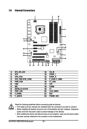
... system may hang. • These fan headers are : 360 KB, 720 KB, 1.2 MB, 1.44 MB, and 2.88 MB. The types of different color. 34 33 GA-EP45C-DS3R/DS3 Motherboard 2 1 - 24 - Before connecting a floppy disk drive, be sure to prevent your CPU and system from overheating. Most fan headers possess a foolproof insertion design. Do...
... system may hang. • These fan headers are : 360 KB, 720 KB, 1.2 MB, 1.44 MB, and 2.88 MB. The types of different color. 34 33 GA-EP45C-DS3R/DS3 Motherboard 2 1 - 24 - Before connecting a floppy disk drive, be sure to prevent your CPU and system from overheating. Most fan headers possess a foolproof insertion design. Do...

Manual
Page 25
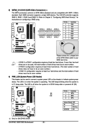
... SATA 1.5Gb/s standard. Please connect the L-shaped end of the IDE devices (for example, master or slave). (For information about configuring master/slave settings for GA-EP45C-DS3. - 25 - Each SATA connector supports a single SATA device. Hardware Installation If you wish to connect two IDE devices, remember to set the jumpers and the...
... SATA 1.5Gb/s standard. Please connect the L-shaped end of the IDE devices (for example, master or slave). (For information about configuring master/slave settings for GA-EP45C-DS3. - 25 - Each SATA connector supports a single SATA device. Hardware Installation If you wish to connect two IDE devices, remember to set the jumpers and the...
Manual
Page 26
... Definition 1 MPD+ 1 2 MPD- 3 MPD- The LED is off when the system is operating. Refer to Chapter 5, "Configuring SATA Hard Drive(s)," for GA-EP45C-DS3R. Definition 1 GND 2 TXP SATA2_4 SATA2_2 SATA2_0 3 TXN 7 1 4 GND 1 7 5 RXN 6 RXP SATA2_5 SATA2_3 SATA2_1 7 GND Please connect the L-shaped... power LED on when the system is in S1 sleep state. The LED is on the chassis to indicate system power status. GA-EP45C-DS3R/DS3 Motherboard - 26 - Each SATA connector supports a single SATA device. Pin No. 8) SATA2_0/1/2/3/4/5 (SATA 3Gb/s Connectors) The ...
... Definition 1 MPD+ 1 2 MPD- 3 MPD- The LED is off when the system is operating. Refer to Chapter 5, "Configuring SATA Hard Drive(s)," for GA-EP45C-DS3R. Definition 1 GND 2 TXP SATA2_4 SATA2_2 SATA2_0 3 TXN 7 1 4 GND 1 7 5 RXN 6 RXP SATA2_5 SATA2_3 SATA2_1 7 GND Please connect the L-shaped... power LED on when the system is in S1 sleep state. The LED is on the chassis to indicate system power status. GA-EP45C-DS3R/DS3 Motherboard - 26 - Each SATA connector supports a single SATA device. Pin No. 8) SATA2_0/1/2/3/4/5 (SATA 3Gb/s Connectors) The ...

Manual
Page 28
.... 12) CD_IN (CD In Connector, Black) You may connect your chassis front panel audio module to the header. Pin No. Definition 1 CD-L 2 GND 3 GND 4 CD-R 1 GA-EP45C-DS3R/DS3 Motherboard - 28 - Incorrect connection between the module connector and the motherboard header will make the device unable to activate AC'97 functioninality via the audio...
.... 12) CD_IN (CD In Connector, Black) You may connect your chassis front panel audio module to the header. Pin No. Definition 1 CD-L 2 GND 3 GND 4 CD-R 1 GA-EP45C-DS3R/DS3 Motherboard - 28 - Incorrect connection between the module connector and the motherboard header will make the device unable to activate AC'97 functioninality via the audio...
Manual
Page 30
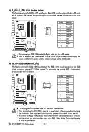
GA-EP45C-DS3R/DS3 Motherboard - 30 - The IEEE 1394a header can provide two USB ports via an optional IEEE 1394a bracket. Each USB header can provide one end of ...
GA-EP45C-DS3R/DS3 Motherboard - 30 - The IEEE 1394a header can provide two USB ports via an optional IEEE 1394a bracket. Each USB header can provide one end of ...
Manual
Page 32
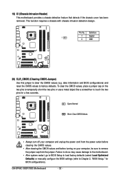
... the two pins for BIOS configurations). To clear the CMOS values, place a jumper cap on your computer and unplug the power cord from the jumper. GA-EP45C-DS3R/DS3 Motherboard - 32 - Pin No. Open: Normal Short: Clear CMOS Values • Always turn off your computer, be sure to remove the jumper cap from the...
... the two pins for BIOS configurations). To clear the CMOS values, place a jumper cap on your computer and unplug the power cord from the jumper. GA-EP45C-DS3R/DS3 Motherboard - 32 - Pin No. Open: Normal Short: Clear CMOS Values • Always turn off your computer, be sure to remove the jumper cap from the...
Manual
Page 34
GA-EP45C-DS3R/DS3 Motherboard - 34 -
GA-EP45C-DS3R/DS3 Motherboard - 34 -


