
Manual
Page 4
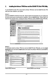
... button and "Xpress Install" will automatically scan your system and list all of Smart TPM to the Install New Utilities menu. Some motherboard driver disks include the Smart TPM utility in "Xpress Install." Click the "Install All" button on the right of the selected drivers..., including the Infineon TPM driver. 2.2. Installing the Infineon TPM Driver Insert the GIGABYTE motherboard driver disk. Click the Install button on the "Xpress Install" main menu to install. 2. Installing the Smart TPM Utility Click the tab ...
... button and "Xpress Install" will automatically scan your system and list all of Smart TPM to the Install New Utilities menu. Some motherboard driver disks include the Smart TPM utility in "Xpress Install." Click the "Install All" button on the right of the selected drivers..., including the Infineon TPM driver. 2.2. Installing the Infineon TPM Driver Insert the GIGABYTE motherboard driver disk. Click the Install button on the "Xpress Install" main menu to install. 2. Installing the Smart TPM Utility Click the tab ...

Manual
Page 7
... the initialization of the TPM chip and the setups of the TPM User Password, your phone. Before creating a Bluetooth cell phone key, make sure your motherboard includes a Bluetooth receiver and turn on the search and Bluetooth functions on your cell phone. Upon completing the steps above, click OK to use as...
... the initialization of the TPM chip and the setups of the TPM User Password, your phone. Before creating a Bluetooth cell phone key, make sure your motherboard includes a Bluetooth receiver and turn on the search and Bluetooth functions on your cell phone. Upon completing the steps above, click OK to use as...

Manual
Page 19
...'t display your Bluetooth-enabled cell phone, click Refresh to let Smart TPM re-detect the device.) Before creating a Bluetooth cell phone key, make sure your motherboard includes a Bluetooth receiver and turn off or reset your computer when a USB key is being created. • If you enter the TPM User Password incorrectly...
...'t display your Bluetooth-enabled cell phone, click Refresh to let Smart TPM re-detect the device.) Before creating a Bluetooth cell phone key, make sure your motherboard includes a Bluetooth receiver and turn off or reset your computer when a USB key is being created. • If you enter the TPM User Password incorrectly...
Manual
Page 3
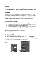
... system and list all of the Infineon TPM Driver and GIGABYTE Ultra TPM items. Install the Infineon TPM driver. Installing the Infineon TPM Driver and the GIGABYTE Ultra TPM Utility To use GIGABYTE's Ultra TPM, ensure that are recommended for installation. 2. Method 1: Insert the GIGABYTE motherboard driver disk. "Xpress Install" will install all the drivers...
... system and list all of the Infineon TPM Driver and GIGABYTE Ultra TPM items. Install the Infineon TPM driver. Installing the Infineon TPM Driver and the GIGABYTE Ultra TPM Utility To use GIGABYTE's Ultra TPM, ensure that are recommended for installation. 2. Method 1: Insert the GIGABYTE motherboard driver disk. "Xpress Install" will install all the drivers...
Manual
Page 1
GA-EP45-UD3P/ GA-EP45-UD3R/ GA-EP45-UD3 LGA775 socket motherboard for Intel® Core™ processor family/ Intel® Pentium® processor family/Intel® Celeron® processor family User's Manual Rev. 1601 12ME-EP45U3P-1601R
GA-EP45-UD3P/ GA-EP45-UD3R/ GA-EP45-UD3 LGA775 socket motherboard for Intel® Core™ processor family/ Intel® Pentium® processor family/Intel® Celeron® processor family User's Manual Rev. 1601 12ME-EP45U3P-1601R

Manual
Page 2
Motherboard GA-EP45-UD3P/GA-EP45-UD3R/GA-EP45-UD3 Sept. 15, 2008 Motherboard GA-EP45-UD3P/GA-EP45-UD3R/ GA-EP45-UD3 Sept. 15, 2008
Motherboard GA-EP45-UD3P/GA-EP45-UD3R/GA-EP45-UD3 Sept. 15, 2008 Motherboard GA-EP45-UD3P/GA-EP45-UD3R/ GA-EP45-UD3 Sept. 15, 2008
Manual
Page 3
..., drivers, or when looking for technical information. No part of this : "REV: X.X." For product-related information, check on our website at: http://www.gigabyte.com.tw Identifying Your Motherboard Revision The revision number on how to use of this manual are legally registered to assist in any form or by any means...
..., drivers, or when looking for technical information. No part of this : "REV: X.X." For product-related information, check on our website at: http://www.gigabyte.com.tw Identifying Your Motherboard Revision The revision number on how to use of this manual are legally registered to assist in any form or by any means...

Manual
Page 4
Table of Contents Box Contents...6 Optional Items...6 GA-EP45-UD3P/UD3R/UD3 Motherboard Layout 7 Block Diagram...8 Chapter 1 Hardware Installation 9 1-1 Installation Precautions 9 1-2 Product Specifications 10 1-3 Installing the CPU and CPU Cooler 13 1-3-1 Installing the CPU 13 1-3-2 Installing the CPU ...
Table of Contents Box Contents...6 Optional Items...6 GA-EP45-UD3P/UD3R/UD3 Motherboard Layout 7 Block Diagram...8 Chapter 1 Hardware Installation 9 1-1 Installation Precautions 9 1-2 Product Specifications 10 1-3 Installing the CPU and CPU Cooler 13 1-3-1 Installing the CPU 13 1-3-2 Installing the CPU ...
Manual
Page 6
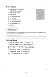
... port cable (Part No. 12CF1-1CM001-3*R) LPT port cable (Part No. 12CF1-1LP001-0*R) - 6 - The box contents are for reference only. k Only for GA-EP45-UD3P. Box Contents GA-EP45-UD3P, GA-EP45-UD3R, or GA-EP45-UD3 motherboard Motherboard driver disk User's Manual Quick Installation Guide One IDE cable Four SATA 3Gb/s cables jk Two SATA 3Gb/s cables l One SATA bracket jk...
... port cable (Part No. 12CF1-1CM001-3*R) LPT port cable (Part No. 12CF1-1LP001-0*R) - 6 - The box contents are for reference only. k Only for GA-EP45-UD3P. Box Contents GA-EP45-UD3P, GA-EP45-UD3R, or GA-EP45-UD3 motherboard Motherboard driver disk User's Manual Quick Installation Guide One IDE cable Four SATA 3Gb/s cables jk Two SATA 3Gb/s cables l One SATA bracket jk...

Manual
Page 7
GA-EP45-UD3P/UD3R/UD3 Motherboard Layout KB_MS R_SPDIF USB_1394_2 ATX_12V_2X4 USB_1394_1 USB_LAN2 j PWR_FAN LGA775 CPU_FAN PHASE_LED ATX GA-EP45-UD3P/UD3R/UD3 USB_LAN1 RTL8111C j AUDIO F_AUDIO SYS_FAN1 PCIEX1_1 RTL8111C PCIEX1_2 PCIEX16_1 CODEC PCIEX1_3 BAT ... DDR2_1 DDR2_2 Intel® ICH10R jk Intel® ICH10 l GIGABYTE SATA2 SATA2_4 SATA2_2 SATA2_0 SATA2_5 SATA2_3 SATA2_1 TPM IC j M_BIOS B_BIOS TSB43AB23 FDD PWR_LED CLR_CMOS COMA LPT F1_1394 F_USB2 F_USB1 F_PANEL GSATA2_1 j Only for GA-EP45-UD3. - 7 - l Only for GA-EP45-UD3P. k Only for GA-EP45-UD3R.
GA-EP45-UD3P/UD3R/UD3 Motherboard Layout KB_MS R_SPDIF USB_1394_2 ATX_12V_2X4 USB_1394_1 USB_LAN2 j PWR_FAN LGA775 CPU_FAN PHASE_LED ATX GA-EP45-UD3P/UD3R/UD3 USB_LAN1 RTL8111C j AUDIO F_AUDIO SYS_FAN1 PCIEX1_1 RTL8111C PCIEX1_2 PCIEX16_1 CODEC PCIEX1_3 BAT ... DDR2_1 DDR2_2 Intel® ICH10R jk Intel® ICH10 l GIGABYTE SATA2 SATA2_4 SATA2_2 SATA2_0 SATA2_5 SATA2_3 SATA2_1 TPM IC j M_BIOS B_BIOS TSB43AB23 FDD PWR_LED CLR_CMOS COMA LPT F1_1394 F_USB2 F_USB1 F_PANEL GSATA2_1 j Only for GA-EP45-UD3. - 7 - l Only for GA-EP45-UD3P. k Only for GA-EP45-UD3R.

Manual
Page 9
... to wear an electrostatic discharge (ESD) wrist strap when handling electronic com- Chapter 1 Hardware Installation 1-1 Installation Precautions The motherboard contains numerous delicate electronic circuits and components which can lead to damage to system components as well as physical harm to the... electrostatic shielding container. • Before unplugging the power supply cable from the power outlet before installing or removing the motherboard or other hardware components. • When connecting hardware components to the internal connectors on the computer power during the ...
... to wear an electrostatic discharge (ESD) wrist strap when handling electronic com- Chapter 1 Hardware Installation 1-1 Installation Precautions The motherboard contains numerous delicate electronic circuits and components which can lead to damage to system components as well as physical harm to the... electrostatic shielding container. • Before unplugging the power supply cable from the power outlet before installing or removing the motherboard or other hardware components. • When connecting hardware components to the internal connectors on the computer power during the ...

Manual
Page 12
...; 30.5cm x 24.4cm j Only for GA-EP45-UD3P. (Note 1) Due to Windows Vista/XP 32-bit operating system limitation, when more than 4 GB. (Note 2) For optimum performance, if only one PCI Express graphics card is supported will be sure to install it in EasyTune may differ by motherboard model. I/O w Hardware Monitor w w w w w w BIOS w w w w Unique...
...; 30.5cm x 24.4cm j Only for GA-EP45-UD3P. (Note 1) Due to Windows Vista/XP 32-bit operating system limitation, when more than 4 GB. (Note 2) For optimum performance, if only one PCI Express graphics card is supported will be sure to install it in EasyTune may differ by motherboard model. I/O w Hardware Monitor w w w w w w BIOS w w w w Unique...

Manual
Page 13
...prevent hardware damage. • Locate the pin one of the CPU. • Do not turn on the CPU - 13 - Locate the alignment keys on the motherboard CPU socket and the notches on the surface of the CPU. LGA775 CPU Socket Alignment Key LGA775 CPU Alignment Key Pin One Corner of the.... age of the CPU Socket Notch Notch Triangle Pin One Marking on the computer if the CPU cooler is not recommended that the motherboard supports the CPU. (Go to GIGABYTE's website for the peripherals. It is not installed, otherwise overheating and dam- If you may occur. • Set the CPU host ...
...prevent hardware damage. • Locate the pin one of the CPU. • Do not turn on the CPU - 13 - Locate the alignment keys on the motherboard CPU socket and the notches on the surface of the CPU. LGA775 CPU Socket Alignment Key LGA775 CPU Alignment Key Pin One Corner of the.... age of the CPU Socket Notch Notch Triangle Pin One Marking on the computer if the CPU cooler is not recommended that the motherboard supports the CPU. (Go to GIGABYTE's website for the peripherals. It is not installed, otherwise overheating and dam- If you may occur. • Set the CPU host ...

Manual
Page 14
..., always replace the protective socket cover when the CPU is properly inserted, replace the load plate and push the CPU socket lever back into the motherboard CPU socket. B. Step 2: Lift the metal load plate from the CPU socket. (DO NOT touch socket contacts.) Step 3: Remove the protective socket cover from the...
..., always replace the protective socket cover when the CPU is properly inserted, replace the load plate and push the CPU socket lever back into the motherboard CPU socket. B. Step 2: Lift the metal load plate from the CPU socket. (DO NOT touch socket contacts.) Step 3: Remove the protective socket cover from the...

Manual
Page 15
... sign on the male push pin. (Turning the push pin along the direction of the CPU cooler to the CPU fan header (CPU_FAN) on the motherboard. Check that the Male and Female push pins are joined closely. (Refer to your CPU cooler installation manual for instructions on installing the cooler.) Step.... If the push pin is inserted as the example cooler.) Step 1: Apply an even and thin layer of thermal grease on the surface of the motherboard. Use extreme care when removing the CPU cooler because the thermal grease/tape between the CPU cooler and CPU may damage the CPU. - 15 - Push...
... sign on the male push pin. (Turning the push pin along the direction of the CPU cooler to the CPU fan header (CPU_FAN) on the motherboard. Check that the Male and Female push pins are joined closely. (Refer to your CPU cooler installation manual for instructions on installing the cooler.) Step.... If the push pin is inserted as the example cooler.) Step 1: Apply an even and thin layer of thermal grease on the surface of the motherboard. Use extreme care when removing the CPU cooler because the thermal grease/tape between the CPU cooler and CPU may damage the CPU. - 15 - Push...

Manual
Page 16
...if only one direction. If you begin to install the memory: • Make sure that the motherboard supports the memory. The four DDR2 memory sockets are unable to GIGABYTE's website for optimum performance. When memory modules of different capacity and chips are installed, a message ...before installing the memory to be used . (Go to insert the memory, switch the direction. 1-4-1 Dual Channel Memory Configuration This motherboard provides four DDR2 memory sockets and supports Dual Channel Technology. Enabling Dual Channel memory mode will appear during the POST. When enabling ...
...if only one direction. If you begin to install the memory: • Make sure that the motherboard supports the memory. The four DDR2 memory sockets are unable to GIGABYTE's website for optimum performance. When memory modules of different capacity and chips are installed, a message ...before installing the memory to be used . (Go to insert the memory, switch the direction. 1-4-1 Dual Channel Memory Configuration This motherboard provides four DDR2 memory sockets and supports Dual Channel Technology. Enabling Dual Channel memory mode will appear during the POST. When enabling ...

Manual
Page 17
..., make sure to turn off the computer and unplug the power cord from the power outlet to prevent damage to install DDR2 DIMMs on this motherboard. Hardware Installation
..., make sure to turn off the computer and unplug the power cord from the power outlet to prevent damage to install DDR2 DIMMs on this motherboard. Hardware Installation
Manual
Page 18
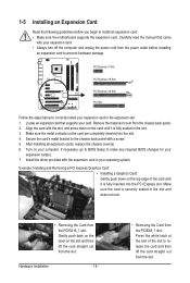
... slot and then lift the card straight out from the slot. Secure the card's metal bracket to install an expansion card: • Make sure the motherboard supports the expansion card. After installing all expansion cards, replace the chassis cover(s). 6. Hardware Installation - 18 - • Removing the Card from the PCIEX8_1 slot: Press...
... slot and then lift the card straight out from the slot. Secure the card's metal bracket to install an expansion card: • Make sure the motherboard supports the expansion card. After installing all expansion cards, replace the chassis cover(s). 6. Hardware Installation - 18 - • Removing the Card from the PCIEX8_1 slot: Press...
Manual
Page 19
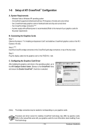
... cards of ATI CrossFireX™ Configuration A. Procedure and driver screen for the power requirement) B. 1-6 Setup of identical brand and chip and correct driver - A CrossFireX-supported motherboard with your graphics cards. Step 3: Plug the display cable into the graphics card on your graphics cards for more information about enabling CrossFireX technology. - 19...
... cards of ATI CrossFireX™ Configuration A. Procedure and driver screen for the power requirement) B. 1-6 Setup of identical brand and chip and correct driver - A CrossFireX-supported motherboard with your graphics cards. Step 3: Plug the display cable into the graphics card on your graphics cards for more information about enabling CrossFireX technology. - 19...

Manual
Page 20
... 3: Connect the power cable from the bracket to the power supply. Hardware Installation - 20 - Follow the steps below to the chassis back panel with the GA-EP45-UD3P/GA-EP45-UD3R only. Step 4: Plug one free PCI slot and secure the SATA bracket to install the SATA bracket: Step 1: Locate one end of the external... of the SATA signal cable into the corresponding connectors when installing. For SATA device in external enclosure, you to connect external SATA device(s) to your motherboard.
... 3: Connect the power cable from the bracket to the power supply. Hardware Installation - 20 - Follow the steps below to the chassis back panel with the GA-EP45-UD3P/GA-EP45-UD3R only. Step 4: Plug one free PCI slot and secure the SATA bracket to install the SATA bracket: Step 1: Locate one end of the external... of the SATA signal cable into the corresponding connectors when installing. For SATA device in external enclosure, you to connect external SATA device(s) to your motherboard.


