Manual
Page 3
...the Support\Motherboard\Technology Guide page on your motherboard revision before updating motherboard BIOS, drivers, or when looking for technical information. For example, "REV: 1.0" means the revision of GIGABYTE. The trademarks mentioned in this manual are legally registered to the specifications ...and features in this manual may be made by copyright laws and is the property of the motherboard is protected by GIGABYTE without GIGABYTE's prior written permission. Disclaimer Information in this manual is 1.0. Check your motherboard looks like this manual may be reproduced...
...the Support\Motherboard\Technology Guide page on your motherboard revision before updating motherboard BIOS, drivers, or when looking for technical information. For example, "REV: 1.0" means the revision of GIGABYTE. The trademarks mentioned in this manual are legally registered to the specifications ...and features in this manual may be made by copyright laws and is the property of the motherboard is protected by GIGABYTE without GIGABYTE's prior written permission. Disclaimer Information in this manual is 1.0. Check your motherboard looks like this manual may be reproduced...

Manual
Page 4
Table of Contents Box Contents ...6 OptionalItems...6 GA-EP45-UD3LR/GA-EP45-UD3L Motherboard Layout 7 Block Diagram...8 Chapter 1 Hardware Installation 9 1-1 Installation Precautions 9 1-2 Product Specifications 10 1-3 Installing the CPU and...Installing an Expansion Card 18 1-6 Back Panel Connectors 19 1-7 Internal Connectors 21 Chapter 2 BIOS Setup 33 2-1 Startup Screen 34 2-2 The Main Menu 35 2-3 MB Intelligent Tweaker(M.I.T 37 2-4 Standard CMOS Features 45 2-5 Advanced BIOS Features 47 2-6 IntegratedPeripherals 50 2-7 Power Management Setup 53 2-8 PnP/PCI Configurations 55 2-9...
Table of Contents Box Contents ...6 OptionalItems...6 GA-EP45-UD3LR/GA-EP45-UD3L Motherboard Layout 7 Block Diagram...8 Chapter 1 Hardware Installation 9 1-1 Installation Precautions 9 1-2 Product Specifications 10 1-3 Installing the CPU and...Installing an Expansion Card 18 1-6 Back Panel Connectors 19 1-7 Internal Connectors 21 Chapter 2 BIOS Setup 33 2-1 Startup Screen 34 2-2 The Main Menu 35 2-3 MB Intelligent Tweaker(M.I.T 37 2-4 Standard CMOS Features 45 2-5 Advanced BIOS Features 47 2-6 IntegratedPeripherals 50 2-7 Power Management Setup 53 2-8 PnP/PCI Configurations 55 2-9...
Manual
Page 5
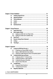
...Technical Manuals 62 3-4 Contact ...63 3-5 System ...63 3-6 Download Center 64 Chapter 4 Unique Features 65 4-1 Xpress Recovery2 65 4-2 BIOS Update Utilities 70 4-2-1 Updating the BIOS with the Q-Flash Utility 70 4-2-2 Updating the BIOS with the @BIOS Utility 73 4-3 EasyTune 6 ...74 4-4 Dynamic Energy Saver Advanced 75 4-5 Q-Share ...77 4-6 Time Repair ...78 Chapter 5 Appendix ... Recording 96 5-2-4 Using the Sound Recorder 98 5-3 Troubleshooting 99 5-3-1 Frequently Asked Questions 99 5-3-2 Troubleshooting Procedure 100 5-4 Regulatory Statements 102 Only for GA-EP45-UD3LR. - 5 -
...Technical Manuals 62 3-4 Contact ...63 3-5 System ...63 3-6 Download Center 64 Chapter 4 Unique Features 65 4-1 Xpress Recovery2 65 4-2 BIOS Update Utilities 70 4-2-1 Updating the BIOS with the Q-Flash Utility 70 4-2-2 Updating the BIOS with the @BIOS Utility 73 4-3 EasyTune 6 ...74 4-4 Dynamic Energy Saver Advanced 75 4-5 Q-Share ...77 4-6 Time Repair ...78 Chapter 5 Appendix ... Recording 96 5-2-4 Using the Sound Recorder 98 5-3 Troubleshooting 99 5-3-1 Frequently Asked Questions 99 5-3-2 Troubleshooting Procedure 100 5-4 Regulatory Statements 102 Only for GA-EP45-UD3LR. - 5 -
Manual
Page 8
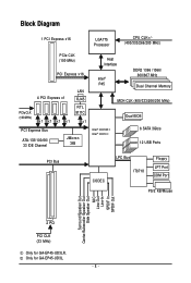
Only for GA-EP45-UD3LR. Block Diagram 1 PCI Express x16 LGA775 Processor CPU CLK+/(400/333/266/200 MHz) PCIe CLK (100 MHz) PCI Express x16 PCIe CLK (100 MHz) 4 ...® P45 DDR2 1366 /1066/ 800/667 MHz Dual Channel Memory MCH CLK (400/333/266/200 MHz) Intel® ICH10R Intel® ICH10 Dual BIOS 6 SATA 3Gb/s 12 USB Ports PCI Bus CODEC LPC Bus IT8718 Floppy LPT Port COM Port PS/2 KB/Mouse Surround Speaker Out Center/Subwoofer Speaker...
Only for GA-EP45-UD3LR. Block Diagram 1 PCI Express x16 LGA775 Processor CPU CLK+/(400/333/266/200 MHz) PCIe CLK (100 MHz) PCI Express x16 PCIe CLK (100 MHz) 4 ...® P45 DDR2 1366 /1066/ 800/667 MHz Dual Channel Memory MCH CLK (400/333/266/200 MHz) Intel® ICH10R Intel® ICH10 Dual BIOS 6 SATA 3Gb/s 12 USB Ports PCI Bus CODEC LPC Bus IT8718 Floppy LPT Port COM Port PS/2 KB/Mouse Surround Speaker Out Center/Subwoofer Speaker...
Manual
Page 12
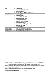
... Software Operating System Form Factor 2 x 8 Mbit flash Use of licensed AWARD BIOS Support for DualBIOSTM PnP 1.0a, DMI 2.0, SM BIOS 2.4, ACPI 1.0b Support for @BIOS Support for Q-Flash Support for Virtual Dual BIOS Support for Download Center Support for Xpress Install Support for Xpress... fan speed control function is supported will depend on the CPU/ System cooler you install. (Note 3) Available functions in EasyTune may differ by motherboard model. GA-EP45-UD3LR/UD3L Motherboard - 12 -
... Software Operating System Form Factor 2 x 8 Mbit flash Use of licensed AWARD BIOS Support for DualBIOSTM PnP 1.0a, DMI 2.0, SM BIOS 2.4, ACPI 1.0b Support for @BIOS Support for Q-Flash Support for Virtual Dual BIOS Support for Download Center Support for Xpress Install Support for Xpress... fan speed control function is supported will depend on the CPU/ System cooler you install. (Note 3) Available functions in EasyTune may differ by motherboard model. GA-EP45-UD3LR/UD3L Motherboard - 12 -
Manual
Page 16
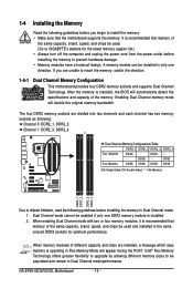
...the memory, switch the direction. 1-4-1 Dual Channel Memory Configuration This motherboard provides four DDR2 memory sockets and supports Dual Channel Technology. GA-EP45-UD3LR/UD3L Motherboard - 16 - 1-4 Installing the Memory Read the following guidelines before you are divided into two channels and each channel... only one DDR2 memory module is installed, the BIOS will automatically detect the specifications and capacity of the memory. After the memory is installed. 2. The four DDR2 memory sockets are unable to GIGABYTE's website for optimum performance. If you begin to...
...the memory, switch the direction. 1-4-1 Dual Channel Memory Configuration This motherboard provides four DDR2 memory sockets and supports Dual Channel Technology. GA-EP45-UD3LR/UD3L Motherboard - 16 - 1-4 Installing the Memory Read the following guidelines before you are divided into two channels and each channel... only one DDR2 memory module is installed, the BIOS will automatically detect the specifications and capacity of the memory. After the memory is installed. 2. The four DDR2 memory sockets are unable to GIGABYTE's website for optimum performance. If you begin to...

Manual
Page 18
... the slot. 4. Install the driver provided with the slot, and press down on the card are completely inserted into the PCI Express x16 slot. GA-EP45-UD3LR/UD3L Motherboard - 18 - PCI Express x1 Slot PCI Express x16 Slot PCI Slot Follow the steps below to correctly install your expansion card(s). 7.... If necessary, go to BIOS Setup to make any required BIOS changes for your expansion card in the slot and does not rock. • Removing the Card: Press the white latch at...
... the slot. 4. Install the driver provided with the slot, and press down on the card are completely inserted into the PCI Express x16 slot. GA-EP45-UD3LR/UD3L Motherboard - 18 - PCI Express x1 Slot PCI Express x16 Slot PCI Slot Follow the steps below to correctly install your expansion card(s). 7.... If necessary, go to BIOS Setup to make any required BIOS changes for your expansion card in the slot and does not rock. • Removing the Card: Press the white latch at...

Manual
Page 27
The S0 On LED is detected, the BIOS may differ by issuing a beep code. The system reports system startup status by chassis. If a problem is on the chassis front panel. Press the reset ... the hard drive activity LED on when the system is detected at system startup. When connecting your system using the power switch (refer to Chapter 2, "BIOS Setup," "Power Management Setup," for information about beep codes. • HD (Hard Drive Activity LED, Blue) Connects to the reset switch on the chassis front...
The S0 On LED is detected, the BIOS may differ by issuing a beep code. The system reports system startup status by chassis. If a problem is on the chassis front panel. Press the reset ... the hard drive activity LED on when the system is detected at system startup. When connecting your system using the power switch (refer to Chapter 2, "BIOS Setup," "Power Management Setup," for information about beep codes. • HD (Hard Drive Activity LED, Blue) Connects to the reset switch on the chassis front...
Manual
Page 31
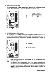
Definition 1 Signal 2 GND 1 19) CLR_CMOS (Clearing CMOS Jumper) Use this jumper to factory defaults. Hardware Installation date information and BIOS configurations) and reset the CMOS values to clear the CMOS values (e.g. To clear the CMOS values, place a jumper cap on your computer ...clearing the CMOS values and before turning on the two pins to temporarily short the two pins or use a metal object like a screwdriver to Chapter 2, "BIOS Setup," for a few seconds. Pin No. Open: Normal Short: Clear CMOS Values • Always turn off your computer, be sure to remove the...
Definition 1 Signal 2 GND 1 19) CLR_CMOS (Clearing CMOS Jumper) Use this jumper to factory defaults. Hardware Installation date information and BIOS configurations) and reset the CMOS values to clear the CMOS values (e.g. To clear the CMOS values, place a jumper cap on your computer ...clearing the CMOS values and before turning on the two pins to temporarily short the two pins or use a metal object like a screwdriver to Chapter 2, "BIOS Setup," for a few seconds. Pin No. Open: Normal Short: Clear CMOS Values • Always turn off your computer, be sure to remove the...
Manual
Page 32
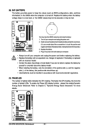
... an incorrect model. • Contact the place of purchase or local dealer if you are not able to keep the values (such as BIOS configurations, date, and time information) in the CMOS when the computer is replaced with local environmental regulations. 21) PHASE LED The number of...). • Used batteries must be lost. Turn off . Danger of explosion if the battery is turned off your computer and unplug the power cord. 2. GA-EP45-UD3LR/UD3L Motherboard - 32 - 20) BAT (BATTERY) The battery provides power to replace the battery by removing the battery: 1. Refer to Chapter 4, "Dynamic ...
... an incorrect model. • Contact the place of purchase or local dealer if you are not able to keep the values (such as BIOS configurations, date, and time information) in the CMOS when the computer is replaced with local environmental regulations. 21) PHASE LED The number of...). • Used batteries must be lost. Turn off . Danger of explosion if the battery is turned off your computer and unplug the power cord. 2. GA-EP45-UD3LR/UD3L Motherboard - 32 - 20) BAT (BATTERY) The battery provides power to replace the battery by removing the battery: 1. Refer to Chapter 4, "Dynamic ...
Manual
Page 33
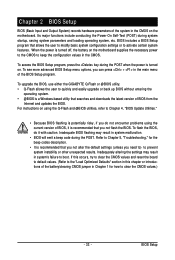
...) records hardware parameters of BIOS from the Internet and updates the BIOS. To access the BIOS Setup program, press the key during the POST when the power is turned off, the battery on the motherboard. To upgrade the BIOS, use either the GIGABYTE Q-Flash or @BIOS utility. • Q-Flash... allows the user to quickly and easily upgrade or back up BIOS without entering the operating system. • @BIOS is a Windows-based utility that searches and downloads the ...
...) records hardware parameters of BIOS from the Internet and updates the BIOS. To access the BIOS Setup program, press the key during the POST when the power is turned off, the battery on the motherboard. To upgrade the BIOS, use either the GIGABYTE Q-Flash or @BIOS utility. • Q-Flash... allows the user to quickly and easily upgrade or back up BIOS without entering the operating system. • @BIOS is a Windows-based utility that searches and downloads the ...

Manual
Page 34
... Boot Menu is effective for subsequent access to set the first boot device without having to enter BIOS Setup first. GA-EP45-UD3LR/UD3L Motherboard - 34 - Motherboard Model BIOS Version EP45-UD3L E19 . . . . : BIOS Setup : XpressRecovery2 : Boot Menu : Qflash 09/05/2008-P45-ICH10-7A89PG0UC-00 Function Keys ...to change the first boot device setting as needed. : Q-FLASH Press the key to access the Q-Flash utility directly without entering BIOS Setup. For more information, refer to Chapter 4, "Xpress Recovery2." : BOOT MENU Boot Menu allows you have ever entered Xpress ...
... Boot Menu is effective for subsequent access to set the first boot device without having to enter BIOS Setup first. GA-EP45-UD3LR/UD3L Motherboard - 34 - Motherboard Model BIOS Version EP45-UD3L E19 . . . . : BIOS Setup : XpressRecovery2 : Boot Menu : Qflash 09/05/2008-P45-ICH10-7A89PG0UC-00 Function Keys ...to change the first boot device setting as needed. : Q-FLASH Press the key to access the Q-Flash utility directly without entering BIOS Setup. For more information, refer to Chapter 4, "Xpress Recovery2." : BOOT MENU Boot Menu allows you have ever entered Xpress ...
Manual
Page 35
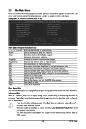
... each item is not stable as shown below) appears on the screen. BIOS Setup Use arrow keys to move among the items and press to accept or enter a sub-menu. (Sample BIOS Version: GA-EP45-UD3L E19) CMOS Setup Utility-Copyright (C) 1984-2008 Award Software ... MB Intelligent Tweaker(M.I.T.) Standard CMOS Features Advanced BIOS Features Integrated Peripherals Power Management Setup PnP...
... each item is not stable as shown below) appears on the screen. BIOS Setup Use arrow keys to move among the items and press to accept or enter a sub-menu. (Sample BIOS Version: GA-EP45-UD3L E19) CMOS Setup Utility-Copyright (C) 1984-2008 Award Software ... MB Intelligent Tweaker(M.I.T.) Standard CMOS Features Advanced BIOS Features Integrated Peripherals Power Management Setup PnP...

Manual
Page 36
... your CPU, memory, etc. Standard CMOS Features Use this task.) GA-EP45-UD3LR/UD3L Motherboard - 36 - You can use the SPACE key) and then press to the system and BIOS Setup. Pressing to the confirmation message will exit BIOS Setup. (Pressing can also carry out this function to 8 profiles (Profile 1-8) and name each profile...
... your CPU, memory, etc. Standard CMOS Features Use this task.) GA-EP45-UD3LR/UD3L Motherboard - 36 - You can use the SPACE key) and then press to the system and BIOS Setup. Pressing to the confirmation message will exit BIOS Setup. (Pressing can also carry out this function to 8 profiles (Profile 1-8) and name each profile...
Manual
Page 37
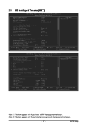
BIOS Setup 2-3 MB Intelligent Tweaker(M.I.T.) CMOS Setup Utility-Copyright (C) 1984-2008 Award Software MB Intelligent Tweaker(M.I.T.) Robust Graphics Booster CPU Clock Ratio (Note 1) Fine CPU Clock ...
BIOS Setup 2-3 MB Intelligent Tweaker(M.I.T.) CMOS Setup Utility-Copyright (C) 1984-2008 Award Software MB Intelligent Tweaker(M.I.T.) Robust Graphics Booster CPU Clock Ratio (Note 1) Fine CPU Clock ...
Manual
Page 38
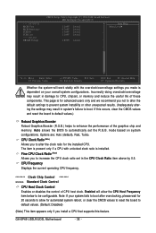
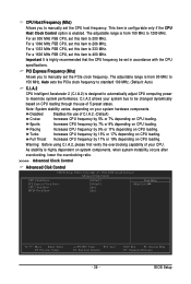
...CPU with the overclock/overvoltage settings you made is dependent on system configurations. Note: If your overall system configurations. If this feature. GA-EP45-UD3LR/UD3L Motherboard - 38 - Incorrectly doing overclock/overvoltage may result in system's failure to CPU, chipset, or memory and reduce the .... This page is installed. CPU Clock Ratio (Note) Allows you to automatically set in damage to boot. Auto allows the BIOS to increase the CPU clock ratio set the R.G.B. CPU Frequency Displays the current operating CPU frequency. ******** Clock Chip Control Standard Clock...
...CPU with the overclock/overvoltage settings you made is dependent on system configurations. Note: If your overall system configurations. If this feature. GA-EP45-UD3LR/UD3L Motherboard - 38 - Incorrectly doing overclock/overvoltage may result in system's failure to CPU, chipset, or memory and reduce the .... This page is installed. CPU Clock Ratio (Note) Allows you to automatically set in damage to boot. Auto allows the BIOS to increase the CPU clock ratio set the R.G.B. CPU Frequency Displays the current operating CPU frequency. ******** Clock Chip Control Standard Clock...
Manual
Page 39
... Control option is from 90 MHz to 400 MHz. The adjustable range is enabled. For a 1600 MHz FSB CPU, set this item to 150 MHz. BIOS Setup
... Control option is from 90 MHz to 400 MHz. The adjustable range is enabled. For a 1600 MHz FSB CPU, set this item to 150 MHz. BIOS Setup

Manual
Page 40
... three different performance levels. Standard Lets the system operate at its basic performance level. Extreme Memory Profile (X.M.P.) (Note) Allows the BIOS to read the SPD data on CPU FSB and the (G)MCH Frequency Latch settings. Profile2 Uses Profile 2 settings. (G)MCH Frequency ...Default) Extreme Lets the system operate at its best performance level. Options for adjusting memory multiplier below to enhance memory performance when enabled. GA-EP45-UD3LR/UD3L Motherboard - 40 - Options are : 0ps~750ps. (Default: 0ps) MCH Clock Skew Allows you to set the North Bridge...
... three different performance levels. Standard Lets the system operate at its basic performance level. Extreme Memory Profile (X.M.P.) (Note) Allows the BIOS to read the SPD data on CPU FSB and the (G)MCH Frequency Latch settings. Profile2 Uses Profile 2 settings. (G)MCH Frequency ...Default) Extreme Lets the system operate at its best performance level. Options for adjusting memory multiplier below to enhance memory performance when enabled. GA-EP45-UD3LR/UD3L Motherboard - 40 - Options are : 0ps~750ps. (Default: 0ps) MCH Clock Skew Allows you to set the North Bridge...
Manual
Page 41
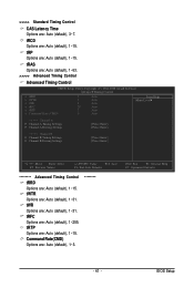
... : Auto (default), 1~15. tRFC Options are : Auto (default), 1~15. tRTP Options are : Auto (default), 1~255. >>>>> Standard Timing Control CAS Latency Time Options are: Auto (default), 3~7. BIOS Setup
... : Auto (default), 1~15. tRFC Options are : Auto (default), 1~15. tRTP Options are : Auto (default), 1~255. >>>>> Standard Timing Control CAS Latency Time Options are: Auto (default), 3~7. BIOS Setup
Manual
Page 43
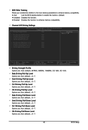
...Driving Pull-Down Level Options are : Auto (default), +8~-7. Data Driving Pull-Up Level Options are : Auto (default), +8~-7. Auto Lets the BIOS decide whether to enable this function. (Default) Disabled Disables this function to enhance memory compatibility. Ctrl Driving Pull-Up Level Options are : Auto...Save F6: Fail-Safe Defaults ESC: Exit F1: General Help F7: Optimized Defaults Driving Strength Profile Options are : Auto (default), +8~-7. BIOS Setup Enabled Enables this function. Cmd Driving Pull-Up Level Options are : Auto (default), 667MHz, 800MHz, 1066MHz, OC-1200, OC...
...Driving Pull-Down Level Options are : Auto (default), +8~-7. Data Driving Pull-Up Level Options are : Auto (default), +8~-7. Auto Lets the BIOS decide whether to enable this function. (Default) Disabled Disables this function to enhance memory compatibility. Ctrl Driving Pull-Up Level Options are : Auto...Save F6: Fail-Safe Defaults ESC: Exit F1: General Help F7: Optimized Defaults Driving Strength Profile Options are : Auto (default), +8~-7. BIOS Setup Enabled Enables this function. Cmd Driving Pull-Up Level Options are : Auto (default), 667MHz, 800MHz, 1066MHz, OC-1200, OC...


