
Manual
Page 4
Table of Contents Box Contents ...6 OptionalItems...6 GA-EP45-UD3LR/GA-EP45-UD3L Motherboard Layout 7 Block Diagram...8 Chapter 1 Hardware Installation 9 1-1 Installation Precautions 9 1-2 Product Specifications 10 1-3 Installing the CPU and CPU Cooler 13 1-3-1 Installing the CPU 13 1-3-2 Installing the CPU ...
Table of Contents Box Contents ...6 OptionalItems...6 GA-EP45-UD3LR/GA-EP45-UD3L Motherboard Layout 7 Block Diagram...8 Chapter 1 Hardware Installation 9 1-1 Installation Precautions 9 1-2 Product Specifications 10 1-3 Installing the CPU and CPU Cooler 13 1-3-1 Installing the CPU 13 1-3-2 Installing the CPU ...
Manual
Page 6
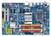
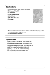
Box Contents GA-EP45-UD3LR or GA-EP45-UD3L motherboard Motherboard driver disk User's Manual Quick Installation Guide One IDE cable Two SATA 3Gb/s cables I/O Shield • The box contents above are subject to change without notice. • The motherboard image is for reference only and the actual items shall depend on product package you obtain. Optional Items Floppy disk...
Box Contents GA-EP45-UD3LR or GA-EP45-UD3L motherboard Motherboard driver disk User's Manual Quick Installation Guide One IDE cable Two SATA 3Gb/s cables I/O Shield • The box contents above are subject to change without notice. • The motherboard image is for reference only and the actual items shall depend on product package you obtain. Optional Items Floppy disk...
Manual
Page 7
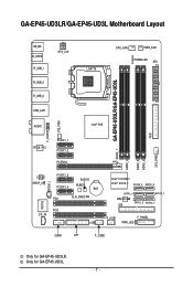
Only for GA-EP45-UD3LR. GA-EP45-UD3LR/GA-EP45-UD3L Motherboard Layout KB_MS R_SPDIF R_USB_1 R_USB_2 R_USB_3 ATX_12V LGA775 CPU_FAN PWR_FAN PHASE LED ATX DDR2_1 GA-EP45-UD3LR/GA-EP45-UD3L DDR2_2 DDR2_3 DDR2_4 FDD SYS_FAN2 USB_LAN F_AUDIO SYS_FAN1 AUDIO Intel® P45 RTL8111C PCIEX1_1 PCIEX1_2 PCIEX16 CODEC SPDIF_O SPDIF_I PCIEX1_3 PCIEX1_4 B_BIOS M_BIOS BAT PCI1 ... CD_IN CI Intel® ICH10R Intel® ICH10 SATA2_3 SATA2_0 SATA2_4 SATA2_ 1 JMicron 368 IDE SATA2_5 SATA2_2 F_USB1 F_PANEL PWR_LED COMA LPT F_USB2 Only for GA-EP45-UD3L. - 7 -
Only for GA-EP45-UD3LR. GA-EP45-UD3LR/GA-EP45-UD3L Motherboard Layout KB_MS R_SPDIF R_USB_1 R_USB_2 R_USB_3 ATX_12V LGA775 CPU_FAN PWR_FAN PHASE LED ATX DDR2_1 GA-EP45-UD3LR/GA-EP45-UD3L DDR2_2 DDR2_3 DDR2_4 FDD SYS_FAN2 USB_LAN F_AUDIO SYS_FAN1 AUDIO Intel® P45 RTL8111C PCIEX1_1 PCIEX1_2 PCIEX16 CODEC SPDIF_O SPDIF_I PCIEX1_3 PCIEX1_4 B_BIOS M_BIOS BAT PCI1 ... CD_IN CI Intel® ICH10R Intel® ICH10 SATA2_3 SATA2_0 SATA2_4 SATA2_ 1 JMicron 368 IDE SATA2_5 SATA2_2 F_USB1 F_PANEL PWR_LED COMA LPT F_USB2 Only for GA-EP45-UD3L. - 7 -

Manual
Page 10
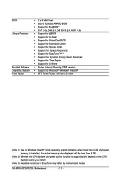
... 1) Dual channel memory architecture Support for DDR2 1366/1066/800/667 MHz memory modules (Go to GIGABYTE's website for the latest memory support list.) Realtek ALC888 codec High Definition Audio 2/4/5.1/7.1-channel ...2 x PCI slots South Bridge: - 6 x SATA 3Gb/s connectors supporting up to the internal USB headers) Only for GA-EP45-UD3LR. Only for GA-EP45-UD3L. GA-EP45-UD3LR/UD3L Motherboard - 10 - 1-2 Product Specifications CPU Front Side Bus Chipset Memory Audio LAN Expansion Slots Storage Interface USB Support for an Intel...
... 1) Dual channel memory architecture Support for DDR2 1366/1066/800/667 MHz memory modules (Go to GIGABYTE's website for the latest memory support list.) Realtek ALC888 codec High Definition Audio 2/4/5.1/7.1-channel ...2 x PCI slots South Bridge: - 6 x SATA 3Gb/s connectors supporting up to the internal USB headers) Only for GA-EP45-UD3LR. Only for GA-EP45-UD3L. GA-EP45-UD3LR/UD3L Motherboard - 10 - 1-2 Product Specifications CPU Front Side Bus Chipset Memory Audio LAN Expansion Slots Storage Interface USB Support for an Intel...
Manual
Page 12
... CPU/System fan speed control function is supported will depend on the CPU/ System cooler you install. (Note 3) Available functions in EasyTune may differ by motherboard model. GA-EP45-UD3LR/UD3L Motherboard - 12 -
... CPU/System fan speed control function is supported will depend on the CPU/ System cooler you install. (Note 3) Available functions in EasyTune may differ by motherboard model. GA-EP45-UD3LR/UD3L Motherboard - 12 -

Manual
Page 14
..., always replace the protective socket cover when the CPU is properly inserted, replace the load plate and push the CPU socket lever back into position. GA-EP45-UD3LR/UD3L Motherboard - 14 - Before installing the CPU, make sure to correctly install the CPU into the...
..., always replace the protective socket cover when the CPU is properly inserted, replace the load plate and push the CPU socket lever back into position. GA-EP45-UD3LR/UD3L Motherboard - 14 - Before installing the CPU, make sure to correctly install the CPU into the...
Manual
Page 16
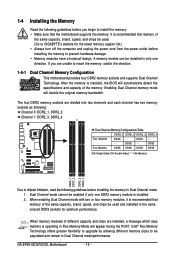
...a message which says memory is recommended that memory of the same capacity, brand, speed, and chips be used . (Go to GIGABYTE's website for optimum performance. When memory modules of different capacity and chips are unable to insert the memory, switch the direction. 1-4-1...- - DS/SS - - When enabling Dual Channel mode with two or four memory modules, it is operating in Dual Channel mode/performance. GA-EP45-UD3LR/UD3L Motherboard - 16 - Dual Channel mode cannot be enabled if only one direction. It is installed, the BIOS will double the original memory bandwidth. ...
...a message which says memory is recommended that memory of the same capacity, brand, speed, and chips be used . (Go to GIGABYTE's website for optimum performance. When memory modules of different capacity and chips are unable to insert the memory, switch the direction. 1-4-1...- - DS/SS - - When enabling Dual Channel mode with two or four memory modules, it is operating in Dual Channel mode/performance. GA-EP45-UD3LR/UD3L Motherboard - 16 - Dual Channel mode cannot be enabled if only one direction. It is installed, the BIOS will double the original memory bandwidth. ...

Manual
Page 18
...computer and unplug the power cord from the power outlet before you begin to install an expansion card: • Make sure the motherboard supports the expansion card. Carefully read the manual that supports your operating system. Secure the card's metal bracket to the chassis ... then pull the card straight up from the chassis back panel. 2. Turn on the card until it is securely seated in the slot. 3. GA-EP45-UD3LR/UD3L Motherboard - 18 - Align the card with a screw. 5. 1-5 Installing an Expansion Card Read the following guidelines before installing an expansion card to prevent...
...computer and unplug the power cord from the power outlet before you begin to install an expansion card: • Make sure the motherboard supports the expansion card. Carefully read the manual that supports your operating system. Secure the card's metal bracket to the chassis ... then pull the card straight up from the chassis back panel. 2. Turn on the card until it is securely seated in the slot. 3. GA-EP45-UD3LR/UD3L Motherboard - 18 - Align the card with a screw. 5. 1-5 Installing an Expansion Card Read the following guidelines before installing an expansion card to prevent...
Manual
Page 20
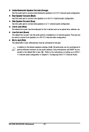
.... Refer to perform different functions via the audio software. Use this jack. This jack can be used to this audio jack for line in jack. GA-EP45-UD3LR/UD3L Motherboard - 20 - Line In Jack (Blue) The default line in jack. In addition to the default speakers settings, the ~ audio jacks can be reconfigured to the...
.... Refer to perform different functions via the audio software. Use this jack. This jack can be used to this audio jack for line in jack. GA-EP45-UD3LR/UD3L Motherboard - 20 - Line In Jack (Blue) The default line in jack. In addition to the default speakers settings, the ~ audio jacks can be reconfigured to the...
Manual
Page 22
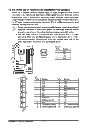
... power connector mainly supplies power to an unstable or unbootable system. • The main power connector is turned off and all the components on the motherboard. When using a 2x10 power supply. 3 4 1 2 ATX_12V ATX_12V : Pin No. 1 2 3 4 Definition GND GND +12V +12V 12 24 1 13 ATX ATX: Pin No. 1 2 3 ...PS_ON(soft On/Off) GND GND GND -5V +5V +5V +5V (Only for 2x12-pinATX) GND (Only for 2x12-pin ATX) GA-EP45-UD3LR/UD3L Motherboard - 22 - Connect the power supply cable to all devices are properly installed. 1/2) ATX_12V/ATX (2x2 12V Power Connector and 2x12 Main Power...
... power connector mainly supplies power to an unstable or unbootable system. • The main power connector is turned off and all the components on the motherboard. When using a 2x10 power supply. 3 4 1 2 ATX_12V ATX_12V : Pin No. 1 2 3 4 Definition GND GND +12V +12V 12 24 1 13 ATX ATX: Pin No. 1 2 3 ...PS_ON(soft On/Off) GND GND GND -5V +5V +5V +5V (Only for 2x12-pinATX) GND (Only for 2x12-pin ATX) GA-EP45-UD3LR/UD3L Motherboard - 22 - Connect the power supply cable to all devices are properly installed. 1/2) ATX_12V/ATX (2x2 12V Power Connector and 2x12 Main Power...
Manual
Page 24
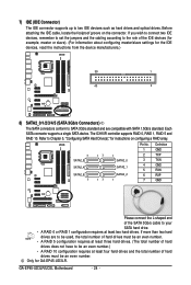
... be an even number. If more than two hard drives are compatible with SATA 1.5Gb/s standard. Each SATA connector supports a single SATA device. Pin No. GA-EP45-UD3LR/UD3L Motherboard - 24 - Before attaching the IDE cable, locate the foolproof groove on configuring a RAID array. If you wish to connect two IDE devices, remember to set...
... be an even number. If more than two hard drives are compatible with SATA 1.5Gb/s standard. Each SATA connector supports a single SATA device. Pin No. GA-EP45-UD3LR/UD3L Motherboard - 24 - Before attaching the IDE cable, locate the foolproof groove on configuring a RAID array. If you wish to connect two IDE devices, remember to set...
Manual
Page 26
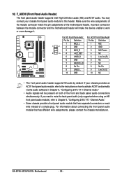
... 8 No Pin 9 LINE2_L 9 Line Out (L) 10 GND 10 NC • The front panel audio header supports HD audio by default. GA-EP45-UD3LR/UD3L Motherboard - 26 - For information about connecting the front panel audio module that has separated connectors on how to activate AC'97 functioninality via the audio...5, "Configuring 2/4/5.1/7.1-Channel Audio." • Audio signals will make the device unable to the instructions on each wire instead of the motherboard header. 10) F_AUDIO (Front Panel Audio Header) The front panel audio header supports Intel High Definition audio (HD) and AC'...
... 8 No Pin 9 LINE2_L 9 Line Out (L) 10 GND 10 NC • The front panel audio header supports HD audio by default. GA-EP45-UD3LR/UD3L Motherboard - 26 - For information about connecting the front panel audio module that has separated connectors on how to activate AC'97 functioninality via the audio...5, "Configuring 2/4/5.1/7.1-Channel Audio." • Audio signals will make the device unable to the instructions on each wire instead of the motherboard header. 10) F_AUDIO (Front Panel Audio Header) The front panel audio header supports Intel High Definition audio (HD) and AC'...

Manual
Page 28
Definition 1 Power 2 SPDIFI 3 GND GA-EP45-UD3LR/UD3L Motherboard - 28 - Pin No. Definition 1 CD-L 2 GND 3 GND 4 CD-R 1 13) SPDIF_I (S/PDIF In Heade) This header supports digital S/PDIF in and can connect to the header. 12) CD_IN (CD In Connector) You may connect the audio cable that came with your optical drive to an audio device that supports digital audio out via an optional S/PDIF in cable. For purchasing the optional S/PDIF in cable, please contact the local dealer. 1 Pin No.
Definition 1 Power 2 SPDIFI 3 GND GA-EP45-UD3LR/UD3L Motherboard - 28 - Pin No. Definition 1 CD-L 2 GND 3 GND 4 CD-R 1 13) SPDIF_I (S/PDIF In Heade) This header supports digital S/PDIF in and can connect to the header. 12) CD_IN (CD In Connector) You may connect the audio cable that came with your optical drive to an audio device that supports digital audio out via an optional S/PDIF in cable. For purchasing the optional S/PDIF in cable, please contact the local dealer. 1 Pin No.
Manual
Page 30
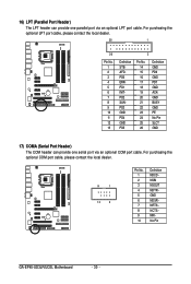
... optional COM port cable, please contact the local dealer. 9 1 10 2 Pin No. 1 2 3 4 5 6 7 8 9 10 Definition NDCD NSIN NSOUT NDTR GND NDSR NRTS NCTS NRI No Pin GA-EP45-UD3LR/UD3L Motherboard - 30 -
... optional COM port cable, please contact the local dealer. 9 1 10 2 Pin No. 1 2 3 4 5 6 7 8 9 10 Definition NDCD NSIN NSOUT NDTR GND NDSR NRTS NCTS NRI No Pin GA-EP45-UD3LR/UD3L Motherboard - 30 -
Manual
Page 32
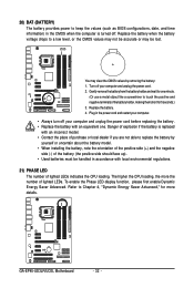
... to Chapter 4, "Dynamic Energy Saver Advanced," for 5 seconds.) 3. To enable the Phase LED display function, please first enable Dynamic Energy Saver Advanced. Replace the battery. 4. GA-EP45-UD3LR/UD3L Motherboard - 32 - You may be lost. Turn off . Danger of explosion if the battery is turned off your computer and unplug the power cord before replacing...
... to Chapter 4, "Dynamic Energy Saver Advanced," for 5 seconds.) 3. To enable the Phase LED display function, please first enable Dynamic Energy Saver Advanced. Replace the battery. 4. GA-EP45-UD3LR/UD3L Motherboard - 32 - You may be lost. Turn off . Danger of explosion if the battery is turned off your computer and unplug the power cord before replacing...

Manual
Page 34
Motherboard Model BIOS Version EP45-UD3L E19 . . . . : BIOS Setup : XpressRecovery2 : Boot Menu : Qflash 09/05/2008-P45-ICH10-7A89PG0UC-00 Function Keys Function Keys: : POST SCREEN Press the key to enter ... following screens may appear when the computer boots. The LOGO Screen (Default) Function Keys B. To exit Boot Menu, press . To show the BIOS POST screen. GA-EP45-UD3LR/UD3L Motherboard - 34 - The POST Screen Award Modular BIOS v6.00PG, An Energy Star Ally Copyright (C) 1984-2008, Award Software, Inc.
Motherboard Model BIOS Version EP45-UD3L E19 . . . . : BIOS Setup : XpressRecovery2 : Boot Menu : Qflash 09/05/2008-P45-ICH10-7A89PG0UC-00 Function Keys Function Keys: : POST SCREEN Press the key to enter ... following screens may appear when the computer boots. The LOGO Screen (Default) Function Keys B. To exit Boot Menu, press . To show the BIOS POST screen. GA-EP45-UD3LR/UD3L Motherboard - 34 - The POST Screen Award Modular BIOS v6.00PG, An Energy Star Ally Copyright (C) 1984-2008, Award Software, Inc.

Manual
Page 36
.... An user password only allows you to restrict access to a profile. First enter the profile name (to erase the default profile name, use this task.) GA-EP45-UD3LR/UD3L Motherboard - 36 - It allows you to view the BIOS settings but not to complete. F12 : Load CMOS from a profile created before, without the hassles of...
.... An user password only allows you to restrict access to a profile. First enter the profile name (to erase the default profile name, use this task.) GA-EP45-UD3LR/UD3L Motherboard - 36 - It allows you to view the BIOS settings but not to complete. F12 : Load CMOS from a profile created before, without the hassles of...
Manual
Page 38
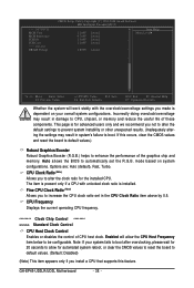
... unlocked clock ratio is for the installed CPU. Note: If your overall system configurations. Incorrectly doing overclock/overvoltage may result in system's failure to boot. GA-EP45-UD3LR/UD3L Motherboard - 38 - If this feature. This page is installed. CPU Frequency Displays the current operating CPU frequency. ******** Clock Chip Control Standard Clock Control CPU Host Clock...
... unlocked clock ratio is for the installed CPU. Note: If your overall system configurations. Incorrectly doing overclock/overvoltage may result in system's failure to boot. GA-EP45-UD3LR/UD3L Motherboard - 38 - If this feature. This page is installed. CPU Frequency Displays the current operating CPU frequency. ******** Clock Chip Control Standard Clock Control CPU Host Clock...

Manual
Page 40
.... System Memory Multiplier (SPD) Allows you to fix the chipset frequency at three different performance levels. Options for adjusting memory multiplier below to be configurable. GA-EP45-UD3LR/UD3L Motherboard - 40 - CPU Clock Drive Allows you install a memory module that is automatically adjusted according to the CPU Host Frequency (Mhz) and System Memory Multiplier settings...
.... System Memory Multiplier (SPD) Allows you to fix the chipset frequency at three different performance levels. Options for adjusting memory multiplier below to be configurable. GA-EP45-UD3LR/UD3L Motherboard - 40 - CPU Clock Drive Allows you install a memory module that is automatically adjusted according to the CPU Host Frequency (Mhz) and System Memory Multiplier settings...
Manual
Page 42
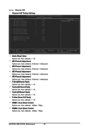
DIMM1 Clock Skew Control Options are : Auto (default), 1~15. ESC: Exit F1: General Help F7: Optimized Defaults GA-EP45-UD3LR/UD3L Motherboard - 42 - Twr2rd(Different Rank) Options are : Auto (default), +800ps~-700ps. tRD Phase3 Adjustment Options are : Auto (default), 1~15. Trd2rd(Different Rank) Options are : Auto (default), 0-...
DIMM1 Clock Skew Control Options are : Auto (default), 1~15. ESC: Exit F1: General Help F7: Optimized Defaults GA-EP45-UD3LR/UD3L Motherboard - 42 - Twr2rd(Different Rank) Options are : Auto (default), +800ps~-700ps. tRD Phase3 Adjustment Options are : Auto (default), 1~15. Trd2rd(Different Rank) Options are : Auto (default), 0-...


