
Manual
Page 7
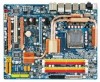
... KB_MS SYS_FAN1 CPU_LED R_SPDIF USB_1394_2 ATX_12V_2X LGA775 CPU_FAN PHASE LED ACPI_LED (S0/1/3/4/5_LED) PWR_FAN USB_1394_1 GA-EP45-DS4P/DS4 DIMM_LED ATX USB_LAN2 USB_LAN1 RTL8111C F_AUDIO AUDIO PCIEX1_1 PE1_LED Intel® P45 RTL8111C PCIEX16_1 NB_FAN CODEC PCIEX1_2 M_BIOS PCIEX1_3 B_BIOS BAT FDD PE_LED ... SATA2_4 SATA2_2 SPDIF_O COMA CLR_CMOS PWR_LED SPDIF_I PW_SW CMOS_SW RST_SW F_PANEL TPM_IC*(Note) SYS_FAN2 F_1394 SATA2_5 SATA2_3 SA_LED F_USB2 F_USB1 SYS_FAN3 "*" Only for GA-EP45-DS4P. (Note) This feature is optional due to different regional policy. - 7 -
... KB_MS SYS_FAN1 CPU_LED R_SPDIF USB_1394_2 ATX_12V_2X LGA775 CPU_FAN PHASE LED ACPI_LED (S0/1/3/4/5_LED) PWR_FAN USB_1394_1 GA-EP45-DS4P/DS4 DIMM_LED ATX USB_LAN2 USB_LAN1 RTL8111C F_AUDIO AUDIO PCIEX1_1 PE1_LED Intel® P45 RTL8111C PCIEX16_1 NB_FAN CODEC PCIEX1_2 M_BIOS PCIEX1_3 B_BIOS BAT FDD PE_LED ... SATA2_4 SATA2_2 SPDIF_O COMA CLR_CMOS PWR_LED SPDIF_I PW_SW CMOS_SW RST_SW F_PANEL TPM_IC*(Note) SYS_FAN2 F_1394 SATA2_5 SATA2_3 SA_LED F_USB2 F_USB1 SYS_FAN3 "*" Only for GA-EP45-DS4P. (Note) This feature is optional due to different regional policy. - 7 -

Manual
Page 10
...TSB43AB23 chip Š Up to 3 IEEE 1394a ports (2 on the back panel, 1 via the IEEE 1394a bracket connected to the internal IEEE 1394a header) GA-EP45-DS4P/DS4 Motherboard - 10 - Support for Teaming Š 1 x PCI Express x16 slot (Note 3) Š 1 x PCI Express x8 slot (The PCIEX16_1 and ...GB of system memory (Note 1) Š Dual channel memory architecture Š Support for DDR2 1200/1066/800/667 MHz memory modules (Go to GIGABYTE's website for the latest memory support list.) Š Realtek ALC889A codec Š High Definition Audio Š 2/4/5.1/7.1-channel Š Support for Dolby®...
...TSB43AB23 chip Š Up to 3 IEEE 1394a ports (2 on the back panel, 1 via the IEEE 1394a bracket connected to the internal IEEE 1394a header) GA-EP45-DS4P/DS4 Motherboard - 10 - Support for Teaming Š 1 x PCI Express x16 slot (Note 3) Š 1 x PCI Express x8 slot (The PCIEX16_1 and ...GB of system memory (Note 1) Š Dual channel memory architecture Š Support for DDR2 1200/1066/800/667 MHz memory modules (Go to GIGABYTE's website for the latest memory support list.) Š Realtek ALC889A codec Š High Definition Audio Š 2/4/5.1/7.1-channel Š Support for Dolby®...

Manual
Page 12
GA-EP45-DS4P/DS4 Motherboard - 12 - "*" Only for GA-EP45-DS4P. When both of the PCIEX16_1 and PCIEX8_1 slots are installing one PCI Express graphics card, be less than 4 GB of licensed AWARD BIOS Š Support ...
GA-EP45-DS4P/DS4 Motherboard - 12 - "*" Only for GA-EP45-DS4P. When both of the PCIEX16_1 and PCIEX8_1 slots are installing one PCI Express graphics card, be less than 4 GB of licensed AWARD BIOS Š Support ...

Manual
Page 14
... Socket Lever Step 1: Completely raise the CPU socket lever. Step 4: Hold the CPU with the socket alignment keys) and gently insert the CPU into position. GA-EP45-DS4P/DS4 Motherboard - 14 - Align the CPU pin one marking (triangle) with the pin one corner of the CPU socket (or you may align the CPU notches...
... Socket Lever Step 1: Completely raise the CPU socket lever. Step 4: Hold the CPU with the socket alignment keys) and gently insert the CPU into position. GA-EP45-DS4P/DS4 Motherboard - 14 - Align the CPU pin one marking (triangle) with the pin one corner of the CPU socket (or you may align the CPU notches...

Manual
Page 16
... Dual Channel Memory Configurations Table DDR2_1 DDR2_2 DDR2_3 DDR2_4 Two Modules DS/SS - - It is operating in Flex Memory Mode will appear during the POST. GA-EP45-DS4P/DS4 Motherboard - 16 - A memory module can be installed in only one DDR2 memory module is installed, the BIOS will double the original memory bandwidth. 1-4 Installing the...
... Dual Channel Memory Configurations Table DDR2_1 DDR2_2 DDR2_3 DDR2_4 Two Modules DS/SS - - It is operating in Flex Memory Mode will appear during the POST. GA-EP45-DS4P/DS4 Motherboard - 16 - A memory module can be installed in only one DDR2 memory module is installed, the BIOS will double the original memory bandwidth. 1-4 Installing the...

Manual
Page 18
... is fully seated in your card. Secure the card's metal bracket to install an expansion card: • Make sure the motherboard supports the expansion card. GA-EP45-DS4P/DS4 Motherboard - 18 - • Removing the Card from the power outlet before you begin to the chassis back panel with the expansion card in the slot...
... is fully seated in your card. Secure the card's metal bracket to install an expansion card: • Make sure the motherboard supports the expansion card. GA-EP45-DS4P/DS4 Motherboard - 18 - • Removing the Card from the power outlet before you begin to the chassis back panel with the expansion card in the slot...

Manual
Page 20
... LAN Port The Gigabit Ethernet LAN port provides Internet connection at up to connect a PS/2 keyboard. USB Port The USB port supports the USB 2.0/1.1 specification. GA-EP45-DS4P/DS4 Motherboard - 20 - 1-7 Back Panel Connectors PS/2 Keyboard and PS/2 Mouse Port Use the upper port (green) to connect a PS/2 mouse and the lower port (purple...
... LAN Port The Gigabit Ethernet LAN port provides Internet connection at up to connect a PS/2 keyboard. USB Port The USB port supports the USB 2.0/1.1 specification. GA-EP45-DS4P/DS4 Motherboard - 20 - 1-7 Back Panel Connectors PS/2 Keyboard and PS/2 Mouse Port Use the upper port (green) to connect a PS/2 mouse and the lower port (purple...

Manual
Page 22
... potential hardware damage due to quickly turn on/off or reset the system or clear the CMOS values. Power Switch Reset Switch Clearing CMOS Switch GA-EP45-DS4P/DS4 Motherboard - 22 - The LED will light up during the POST when the components/devices have a problem. The 7 LEDs indicate if a component (including CPU and memory...
... potential hardware damage due to quickly turn on/off or reset the system or clear the CMOS values. Power Switch Reset Switch Clearing CMOS Switch GA-EP45-DS4P/DS4 Motherboard - 22 - The LED will light up during the POST when the components/devices have a problem. The 7 LEDs indicate if a component (including CPU and memory...

Manual
Page 24
... (Only for 2x4 pin 12V) 2 GND (Only for 2x4 pin 12V) 3 GND 4 GND 5 +12V (Only for 2x4 pin 12V) 6 +12V (Only for 2x12 pin ATX) GA-EP45-DS4P/DS4 Motherboard - 24 - The power connector possesses a foolproof design. If a power supply is used that can withstand high power consumption be used (500W or greater). 1/2) ATX_12V_2X...
... (Only for 2x4 pin 12V) 2 GND (Only for 2x4 pin 12V) 3 GND 4 GND 5 +12V (Only for 2x4 pin 12V) 6 +12V (Only for 2x12 pin ATX) GA-EP45-DS4P/DS4 Motherboard - 24 - The power connector possesses a foolproof design. If a power supply is used that can withstand high power consumption be used (500W or greater). 1/2) ATX_12V_2X...

Manual
Page 26
... (for example, master or slave). (For information about configuring master/slave settings for the IDE devices, read the instructions from the device manufacturers.) 1 2 39 40 GA-EP45-DS4P/DS4 Motherboard - 26 - 7) FDD (Floppy Disk Drive Connector) This connector is typically designated by a stripe of different color. 34 33 2 1 8) IDE (IDE Connector) The IDE connector...
... (for example, master or slave). (For information about configuring master/slave settings for the IDE devices, read the instructions from the device manufacturers.) 1 2 39 40 GA-EP45-DS4P/DS4 Motherboard - 26 - 7) FDD (Floppy Disk Drive Connector) This connector is typically designated by a stripe of different color. 34 33 2 1 8) IDE (IDE Connector) The IDE connector...

Manual
Page 28
... the place of purchase or local dealer if you are not able to replace the battery by removing the battery: 1. The LED is off (S5). GA-EP45-DS4P/DS4 Motherboard - 28 - Pin No. The LED is on the chassis to keep the values (such as BIOS configurations, date, and time information) in the CMOS...
... the place of purchase or local dealer if you are not able to replace the battery by removing the battery: 1. The LED is off (S5). GA-EP45-DS4P/DS4 Motherboard - 28 - Pin No. The LED is on the chassis to keep the values (such as BIOS configurations, date, and time information) in the CMOS...

Manual
Page 30
... chassis provide a front panel audio module that came with your chassis front panel audio module to the header. 1 Pin No. Definition 1 CD-L 2 GND 3 GND 4 CD-R GA-EP45-DS4P/DS4 Motherboard - 30 - You may connect the audio cable that has separated connectors on how to work or even damage it. Definition 1 MIC2_L Pin No. 1 Definition...
... chassis provide a front panel audio module that came with your chassis front panel audio module to the header. 1 Pin No. Definition 1 CD-L 2 GND 3 GND 4 CD-R GA-EP45-DS4P/DS4 Motherboard - 30 - You may connect the audio cable that has separated connectors on how to work or even damage it. Definition 1 MIC2_L Pin No. 1 Definition...

Manual
Page 32
Pin No. Ensure that the cable is securely connected. GA-EP45-DS4P/DS4 Motherboard - 32 - The IEEE 1394a header can provide two USB ports via an optional IEEE 1394a bracket. Each USB header can provide one end of ...
Pin No. Ensure that the cable is securely connected. GA-EP45-DS4P/DS4 Motherboard - 32 - The IEEE 1394a header can provide two USB ports via an optional IEEE 1394a bracket. Each USB header can provide one end of ...

Manual
Page 34
... settings (refer to Chapter 2, "BIOS Setup," for a few seconds. The higher the CPU loading, the more the number of lighted LEDs indicates the CPU loading. GA-EP45-DS4P/DS4 Motherboard - 34 - 21) CLR_CMOS (Clearing CMOS Jumper) Use this jumper to factory defaults. date information and BIOS configurations) and reset the CMOS values to clear...
... settings (refer to Chapter 2, "BIOS Setup," for a few seconds. The higher the CPU loading, the more the number of lighted LEDs indicates the CPU loading. GA-EP45-DS4P/DS4 Motherboard - 34 - 21) CLR_CMOS (Clearing CMOS Jumper) Use this jumper to factory defaults. date information and BIOS configurations) and reset the CMOS values to clear...

Manual
Page 36
... screen. To exit Boot Menu, press . Note: The setting in Boot Menu is effective for subsequent access to XpressRecovery2 during the POST. GA-EP45-DS4P/DS4 Motherboard - 36 - Motherboard Model BIOS Version EP45-DS4P F1a . . . . : BIOS Setup : XpressRecovery2 : Boot Menu : Qflash 04/29/2008-P45-ICH10-7A89PG07C-00 Function Keys Function Keys Function Keys: : POST Screen...
... screen. To exit Boot Menu, press . Note: The setting in Boot Menu is effective for subsequent access to XpressRecovery2 during the POST. GA-EP45-DS4P/DS4 Motherboard - 36 - Motherboard Model BIOS Version EP45-DS4P F1a . . . . : BIOS Setup : XpressRecovery2 : Boot Menu : Qflash 04/29/2008-P45-ICH10-7A89PG07C-00 Function Keys Function Keys Function Keys: : POST Screen...

Manual
Page 38
... to 8 profiles (Profile 1-8) and name each profile. An user password only allows you to view the BIOS settings but not to make changes in effect. GA-EP45-DS4P/DS4 Motherboard - 38 - „ The Functions of the and keys (For the Main Menu Only) ` F11 : Save CMOS to BIOS This function allows you to save... Defaults Fail-Safe defaults are factory settings for the most stable, minimal-performance system operations. „ Load Optimized Defaults Optimized defaults are factory settings for GA-EP45-DS4P.
... to 8 profiles (Profile 1-8) and name each profile. An user password only allows you to view the BIOS settings but not to make changes in effect. GA-EP45-DS4P/DS4 Motherboard - 38 - „ The Functions of the and keys (For the Main Menu Only) ` F11 : Save CMOS to BIOS This function allows you to save... Defaults Fail-Safe defaults are factory settings for the most stable, minimal-performance system operations. „ Load Optimized Defaults Optimized defaults are factory settings for GA-EP45-DS4P.
Manual
Page 40
.... Options are: Auto (default), Fast, Turbo. The item is present only if a CPU with the overclock/overvoltage settings you made is dependent on system configurations. GA-EP45-DS4P/DS4 Motherboard - 40 - CMOS Setup Utility-Copyright (C) 1984-2008 Award Software MB Intelligent Tweaker(M.I.T.) >>> MCH/ICH MCH Core MCH Reference MCH/DRAM Reference ICH I/O ICH Core...
.... Options are: Auto (default), Fast, Turbo. The item is present only if a CPU with the overclock/overvoltage settings you made is dependent on system configurations. GA-EP45-DS4P/DS4 Motherboard - 40 - CMOS Setup Utility-Copyright (C) 1984-2008 Award Software MB Intelligent Tweaker(M.I.T.) >>> MCH/ICH MCH Core MCH Reference MCH/DRAM Reference ICH I/O ICH Core...

Manual
Page 42
Disabled Disables this feature. Options are : 700mV, 800mV (default), 900mV, 1000mV. GA-EP45-DS4P/DS4 Motherboard - 42 - Options are : Auto (default), 200MHz, 266MHz, 333MHz, 400MHz. PCI Express Clock Drive Allows you to set the system memory multiplier. Options are : 700mV, ...
Disabled Disables this feature. Options are : 700mV, 800mV (default), 900mV, 1000mV. GA-EP45-DS4P/DS4 Motherboard - 42 - Options are : Auto (default), 200MHz, 266MHz, 333MHz, 400MHz. PCI Express Clock Drive Allows you to set the system memory multiplier. Options are : 700mV, ...

Manual
Page 44
Twr2wr(Different Rank) Options are : Auto (default), 1~15. GA-EP45-DS4P/DS4 Motherboard - 44 - tRTP Options are : Auto (default), 1~15. tRD Phase0 Adjustment Options are : Auto (default), 1~15. Trd2rd(Different Rank) Options are : Auto (default), 1-Advanced, 0-Normal. ...
Twr2wr(Different Rank) Options are : Auto (default), 1~15. GA-EP45-DS4P/DS4 Motherboard - 44 - tRTP Options are : Auto (default), 1~15. tRD Phase0 Adjustment Options are : Auto (default), 1~15. Trd2rd(Different Rank) Options are : Auto (default), 1-Advanced, 0-Normal. ...

Manual
Page 46
... time. For example, 1 p.m. Select the desired field and use the up arrow or down arrow key to autodetect the parameters of the three methods below: GA-EP45-DS4P/DS4 Motherboard - 46 - 2-4 Standard CMOS Features Date (mm:dd:yy) Time (hh:mm:ss) CMOS Setup Utility-Copyright (C) 1984-2008 Award Software Standard CMOS Features Mon...
... time. For example, 1 p.m. Select the desired field and use the up arrow or down arrow key to autodetect the parameters of the three methods below: GA-EP45-DS4P/DS4 Motherboard - 46 - 2-4 Standard CMOS Features Date (mm:dd:yy) Time (hh:mm:ss) CMOS Setup Utility-Copyright (C) 1984-2008 Award Software Standard CMOS Features Mon...

