
Manual
Page 1
GA-EP45-DS4P/ GA-EP45-DS4 LGA775 socket motherboard for Intel® CoreTM processor family/ Intel® Pentium® processor family/Intel® Celeron® processor family User's Manual Rev. 1003 12ME-EP45DS4-1003R
GA-EP45-DS4P/ GA-EP45-DS4 LGA775 socket motherboard for Intel® CoreTM processor family/ Intel® Pentium® processor family/Intel® Celeron® processor family User's Manual Rev. 1003 12ME-EP45DS4-1003R
Manual
Page 2
Motherboard GA-EP45-DS4P/GA-EP45-DS4 May 15, 2008 Motherboard GA-EP45-DS4P/ GA-EP45-DS4 May 15, 2008
Motherboard GA-EP45-DS4P/GA-EP45-DS4 May 15, 2008 Motherboard GA-EP45-DS4P/ GA-EP45-DS4 May 15, 2008

Manual
Page 4
Table of Contents Box Contents ...6 OptionalItems ...6 GA-EP45-DS4P/GA-EP45-DS4 Motherboard Layout 7 Block Diagram ...8 Chapter 1 Hardware Installation 9 1-1 Installation Precautions 9 1-2 Product Specifications 10 1-3 Installing the CPU and CPU Cooler 13 1-3-1 Installing the CPU 13 1-3-2 Installing the ... 59 2-12 Set Supervisor/User Password 60 2-13 Save & Exit Setup 61 2-14 Exit Without Saving 61 2-15 Security Chip Configuration* (Note 62 "*" Only for GA-EP45-DS4P. - 4 -
Table of Contents Box Contents ...6 OptionalItems ...6 GA-EP45-DS4P/GA-EP45-DS4 Motherboard Layout 7 Block Diagram ...8 Chapter 1 Hardware Installation 9 1-1 Installation Precautions 9 1-2 Product Specifications 10 1-3 Installing the CPU and CPU Cooler 13 1-3-1 Installing the CPU 13 1-3-2 Installing the ... 59 2-12 Set Supervisor/User Password 60 2-13 Save & Exit Setup 61 2-14 Exit Without Saving 61 2-15 Security Chip Configuration* (Note 62 "*" Only for GA-EP45-DS4P. - 4 -

Manual
Page 5
... Function 102 5-2-4 Configuring Microphone Recording 103 5-2-5 Using the Sound Recorder 105 5-3 Troubleshooting 106 5-3-1 Frequently Asked Questions 106 5-3-2 Troubleshooting Procedure 107 Regulatory Statements 109 "*" Only for GA-EP45-DS4P. (Note) This feature is optional due to different regional policy. - 5 -
... Function 102 5-2-4 Configuring Microphone Recording 103 5-2-5 Using the Sound Recorder 105 5-3 Troubleshooting 106 5-3-1 Frequently Asked Questions 106 5-3-2 Troubleshooting Procedure 107 Regulatory Statements 109 "*" Only for GA-EP45-DS4P. (Note) This feature is optional due to different regional policy. - 5 -

Manual
Page 6
Box Contents GA-EP45-DS4P/GA-EP45-DS4 motherboard Motherboard driver disk User's Manual Quick Installation Guide Intel® LGA775 CPU Installation Guide One IDE cable and one floppy disk drive cable Four ...
Box Contents GA-EP45-DS4P/GA-EP45-DS4 motherboard Motherboard driver disk User's Manual Quick Installation Guide Intel® LGA775 CPU Installation Guide One IDE cable and one floppy disk drive cable Four ...

Manual
Page 7
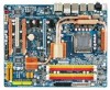
GA-EP45-DS4P/GA-EP45-DS4 Motherboard Layout KB_MS SYS_FAN1 CPU_LED R_SPDIF USB_1394_2 ATX_12V_2X LGA775 CPU_FAN PHASE LED ACPI_LED (S0/1/3/4/5_LED) PWR_FAN USB_1394_1 GA-EP45-DS4P/DS4 DIMM_LED ATX USB_LAN2 USB_LAN1 RTL8111C F_AUDIO AUDIO PCIEX1_1 PE1_LED Intel® P45 RTL8111C PCIEX16_1 NB_FAN CODEC PCIEX1_2 M_BIOS PCIEX1_3 B_BIOS ... COMA CLR_CMOS PWR_LED SPDIF_I PW_SW CMOS_SW RST_SW F_PANEL TPM_IC*(Note) SYS_FAN2 F_1394 SATA2_5 SATA2_3 SA_LED F_USB2 F_USB1 SYS_FAN3 "*" Only for GA-EP45-DS4P. (Note) This feature is optional due to different regional policy. - 7 -
GA-EP45-DS4P/GA-EP45-DS4 Motherboard Layout KB_MS SYS_FAN1 CPU_LED R_SPDIF USB_1394_2 ATX_12V_2X LGA775 CPU_FAN PHASE LED ACPI_LED (S0/1/3/4/5_LED) PWR_FAN USB_1394_1 GA-EP45-DS4P/DS4 DIMM_LED ATX USB_LAN2 USB_LAN1 RTL8111C F_AUDIO AUDIO PCIEX1_1 PE1_LED Intel® P45 RTL8111C PCIEX16_1 NB_FAN CODEC PCIEX1_2 M_BIOS PCIEX1_3 B_BIOS ... COMA CLR_CMOS PWR_LED SPDIF_I PW_SW CMOS_SW RST_SW F_PANEL TPM_IC*(Note) SYS_FAN2 F_1394 SATA2_5 SATA2_3 SA_LED F_USB2 F_USB1 SYS_FAN3 "*" Only for GA-EP45-DS4P. (Note) This feature is optional due to different regional policy. - 7 -

Manual
Page 8
... Speaker Out Center/Subwoofer Speaker Out Side Speaker Out MIC Line-Out Line-In SPDIF In SPDIF Out 1 PCI PCI CLK (33 MHz) "*" Only for GA-EP45-DS4P. (Note) This feature is optional due to different regional policy. - 8 -
... Speaker Out Center/Subwoofer Speaker Out Side Speaker Out MIC Line-Out Line-In SPDIF In SPDIF Out 1 PCI PCI CLK (33 MHz) "*" Only for GA-EP45-DS4P. (Note) This feature is optional due to different regional policy. - 8 -

Manual
Page 10
...174; Pentium® Dual-Core processor/Intel® Celeron® processor in the LGA 775 package (Go to GIGABYTE's website for the latest CPU support list.) Š L2 cache varies with CPU Š 1600/1333/1066... Š Dual channel memory architecture Š Support for DDR2 1200/1066/800/667 MHz memory modules (Go to GIGABYTE's website for the latest memory support list.) Š Realtek ALC889A codec Š High Definition Audio Š 2/4/5.1/7.1-... Š South Bridge: - 6 x SATA 3Gb/s connectors supporting up to the internal IEEE 1394a header) GA-EP45-DS4P/DS4 Motherboard - 10 -
...174; Pentium® Dual-Core processor/Intel® Celeron® processor in the LGA 775 package (Go to GIGABYTE's website for the latest CPU support list.) Š L2 cache varies with CPU Š 1600/1333/1066... Š Dual channel memory architecture Š Support for DDR2 1200/1066/800/667 MHz memory modules (Go to GIGABYTE's website for the latest memory support list.) Š Realtek ALC889A codec Š High Definition Audio Š 2/4/5.1/7.1-... Š South Bridge: - 6 x SATA 3Gb/s connectors supporting up to the internal IEEE 1394a header) GA-EP45-DS4P/DS4 Motherboard - 10 -

Manual
Page 12
... CPU fan speed control function is supported will depend on the CPU cooler you install. (Note 6) Available functions in the PCIEX16_1 slot for optimum performance. GA-EP45-DS4P/DS4 Motherboard - 12 - "*" Only for GA-EP45-DS4P. When both of physical memory is installed, the actual memory size displayed will be sure to different regional policy.
... CPU fan speed control function is supported will depend on the CPU cooler you install. (Note 6) Available functions in the PCIEX16_1 slot for optimum performance. GA-EP45-DS4P/DS4 Motherboard - 12 - "*" Only for GA-EP45-DS4P. When both of physical memory is installed, the actual memory size displayed will be sure to different regional policy.

Manual
Page 14
... one marking (triangle) with the pin one corner of the CPU socket (or you may align the CPU notches with your thumb and index fingers. GA-EP45-DS4P/DS4 Motherboard - 14 - Follow the steps below to the CPU.
... one marking (triangle) with the pin one corner of the CPU socket (or you may align the CPU notches with your thumb and index fingers. GA-EP45-DS4P/DS4 Motherboard - 14 - Follow the steps below to the CPU.

Manual
Page 16
... cord from the power outlet before installing the memory in Dual Channel mode. 1. The four DDR2 memory sockets are unable to GIGABYTE's website for optimum performance. Dual Channel mode cannot be enabled if only one direction. It is recommended that the motherboard supports the...sockets as following: Channel 0: DDR2_1, DDR2_2 Channel 1: DDR2_3, DDR2_4 Dual Channel Memory Configurations Table DDR2_1 DDR2_2 DDR2_3 DDR2_4 Two Modules DS/SS - - GA-EP45-DS4P/DS4 Motherboard - 16 - DS/SS Four Modules DS/SS DS/SS DS/SS DS/SS (SS=Single-Sided, DS=Double-Sided, "- -"=No Memory...
... cord from the power outlet before installing the memory in Dual Channel mode. 1. The four DDR2 memory sockets are unable to GIGABYTE's website for optimum performance. Dual Channel mode cannot be enabled if only one direction. It is recommended that the motherboard supports the...sockets as following: Channel 0: DDR2_1, DDR2_2 Channel 1: DDR2_3, DDR2_4 Dual Channel Memory Configurations Table DDR2_1 DDR2_2 DDR2_3 DDR2_4 Two Modules DS/SS - - GA-EP45-DS4P/DS4 Motherboard - 16 - DS/SS Four Modules DS/SS DS/SS DS/SS DS/SS (SS=Single-Sided, DS=Double-Sided, "- -"=No Memory...

Manual
Page 18
... card is fully inserted into the slot. 4. Make sure the metal contacts on the slot and then lift the card straight out from the slot. GA-EP45-DS4P/DS4 Motherboard - 18 - • Removing the Card from the PCIEX8_1/PCIEX4_1 Slot: Press the white latch at the end of the card until it is securely...
... card is fully inserted into the slot. 4. Make sure the metal contacts on the slot and then lift the card straight out from the slot. GA-EP45-DS4P/DS4 Motherboard - 18 - • Removing the Card from the PCIEX8_1/PCIEX4_1 Slot: Press the white latch at the end of the card until it is securely...

Manual
Page 20
... audio system that supports digital optical audio. Use this port for an IEEE 1394a device. The following describes the states of the LAN port LEDs. GA-EP45-DS4P/DS4 Motherboard - 20 - Use this port for USB devices such as an USB keyboard/mouse, USB printer, USB flash drive and etc. Before using this feature...
... audio system that supports digital optical audio. Use this port for an IEEE 1394a device. The following describes the states of the LAN port LEDs. GA-EP45-DS4P/DS4 Motherboard - 20 - Use this port for USB devices such as an USB keyboard/mouse, USB printer, USB flash drive and etc. Before using this feature...

Manual
Page 22
... a component (including CPU and memory) or a device (including PCI and PCIe cards and IDE/SATA devices) works abnormally. Power Switch Reset Switch Clearing CMOS Switch GA-EP45-DS4P/DS4 Motherboard - 22 - 1-8 Onboard LEDs and Switches Diagnostic LEDs This motherboard has 7 onboard LEDs controlled by the system BIOS. Quick Switches This motherboard has 3 quick switches...
... a component (including CPU and memory) or a device (including PCI and PCIe cards and IDE/SATA devices) works abnormally. Power Switch Reset Switch Clearing CMOS Switch GA-EP45-DS4P/DS4 Motherboard - 22 - 1-8 Onboard LEDs and Switches Diagnostic LEDs This motherboard has 7 onboard LEDs controlled by the system BIOS. Quick Switches This motherboard has 3 quick switches...

Manual
Page 24
... 3.3V -12V GND PS_ON(soft On/Off) GND GND GND -5V +5V +5V +5V (Only for 2x12 pin ATX) GND (Only for 2x12 pin ATX) GA-EP45-DS4P/DS4 Motherboard - 24 -
... 3.3V -12V GND PS_ON(soft On/Off) GND GND GND -5V +5V +5V +5V (Only for 2x12 pin ATX) GND (Only for 2x12 pin ATX) GA-EP45-DS4P/DS4 Motherboard - 24 -

Manual
Page 26
... (for example, master or slave). (For information about configuring master/slave settings for the IDE devices, read the instructions from the device manufacturers.) 1 2 39 40 GA-EP45-DS4P/DS4 Motherboard - 26 - The types of floppy disk drives supported are: 360 KB, 720 KB, 1.2 MB, 1.44 MB, and 2.88 MB. Before attaching the IDE cable...
... (for example, master or slave). (For information about configuring master/slave settings for the IDE devices, read the instructions from the device manufacturers.) 1 2 39 40 GA-EP45-DS4P/DS4 Motherboard - 26 - The types of floppy disk drives supported are: 360 KB, 720 KB, 1.2 MB, 1.44 MB, and 2.88 MB. Before attaching the IDE cable...

Manual
Page 28
... is off when the system is turned off. Pin No. Replace the battery. 4. Gently remove the battery from the battery holder and wait for one . GA-EP45-DS4P/DS4 Motherboard - 28 -
... is off when the system is turned off. Pin No. Replace the battery. 4. Gently remove the battery from the battery holder and wait for one . GA-EP45-DS4P/DS4 Motherboard - 28 -

Manual
Page 30
... HD audio by default. Make sure the wire assignments of the module connector match the pin assignments of a single plug. Definition 1 CD-L 2 GND 3 GND 4 CD-R GA-EP45-DS4P/DS4 Motherboard - 30 - For HD Front Panel Audio: For AC'97 Front Panel Audio: 1 2 Pin No. For information about connecting the front panel audio module that...
... HD audio by default. Make sure the wire assignments of the module connector match the pin assignments of a single plug. Definition 1 CD-L 2 GND 3 GND 4 CD-R GA-EP45-DS4P/DS4 Motherboard - 30 - For HD Front Panel Audio: For AC'97 Front Panel Audio: 1 2 Pin No. For information about connecting the front panel audio module that...

Manual
Page 32
...; Prior to installing the USB bracket, be sure to turn off your computer and then attach the other end of the cable to USB 2.0/1.1 specification. GA-EP45-DS4P/DS4 Motherboard - 32 - 17) F_USB1/F_USB2 (USB Headers, Yellow) The headers conform to the IEEE 1394a device. For purchasing the optional USB bracket, please contact the...
...; Prior to installing the USB bracket, be sure to turn off your computer and then attach the other end of the cable to USB 2.0/1.1 specification. GA-EP45-DS4P/DS4 Motherboard - 32 - 17) F_USB1/F_USB2 (USB Headers, Yellow) The headers conform to the IEEE 1394a device. For purchasing the optional USB bracket, please contact the...

Manual
Page 34
... BIOS settings (refer to Chapter 2, "BIOS Setup," for a few seconds. date information and BIOS configurations) and reset the CMOS values to clear the CMOS values (e.g. GA-EP45-DS4P/DS4 Motherboard - 34 - The higher the CPU loading, the more the number of lighted LEDs indicates the CPU loading. Open: Normal Short: Clear CMOS Values •...
... BIOS settings (refer to Chapter 2, "BIOS Setup," for a few seconds. date information and BIOS configurations) and reset the CMOS values to clear the CMOS values (e.g. GA-EP45-DS4P/DS4 Motherboard - 34 - The higher the CPU loading, the more the number of lighted LEDs indicates the CPU loading. Open: Normal Short: Clear CMOS Values •...