
Manual
Page 5
... Audio Input and Output 90 5-2-1 Configuring 2/4/5.1/7.1-Channel Audio 90 5-2-2 Installing the S/PDIF In Cable (Optional 92 5-2-3 Configuring Microphone Recording 94 5-2-4 Using the Sound Recorder 96 5-3 Troubleshooting 97 5-3-1 Frequently Asked Questions 97 5-3-2 Troubleshooting Procedure 98 5-4 Regulatory Statements 100 Only for GA-EP45-DS3LR. - 5 -
... Audio Input and Output 90 5-2-1 Configuring 2/4/5.1/7.1-Channel Audio 90 5-2-2 Installing the S/PDIF In Cable (Optional 92 5-2-3 Configuring Microphone Recording 94 5-2-4 Using the Sound Recorder 96 5-3 Troubleshooting 97 5-3-1 Frequently Asked Questions 97 5-3-2 Troubleshooting Procedure 98 5-4 Regulatory Statements 100 Only for GA-EP45-DS3LR. - 5 -
Manual
Page 27
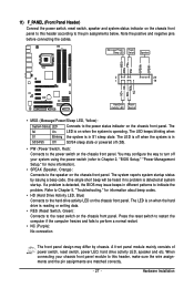
... keeps blinking when S1 Blinking the system is in different patterns to the hard drive activity LED on the chassis front panel. Refer to Chapter 5, "Troubleshooting," for more information). • SPEAK (Speaker, Orange): Connects to the power status indicator on the chassis front panel. When connecting your system using the power...
... keeps blinking when S1 Blinking the system is in different patterns to the hard drive activity LED on the chassis front panel. Refer to Chapter 5, "Troubleshooting," for more information). • SPEAK (Speaker, Orange): Connects to the power status indicator on the chassis front panel. When connecting your system using the power...
Manual
Page 33
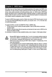
... in the main menu of the BIOS Setup program. To access the BIOS Setup program, press the key during the POST. Refer to Chapter 5, "Troubleshooting," for how to clear the CMOS values.) - 33 - When the power is turned on the motherboard. BIOS Setup BIOS includes a BIOS Setup program... Defaults" section in this chapter or introductions of the battery/clearing CMOS jumper in the CMOS on . To upgrade the BIOS, use either the GIGABYTE Q-Flash or @BIOS utility. • Q-Flash allows the user to activate certain system features. If this occurs, try to clear the CMOS ...
... in the main menu of the BIOS Setup program. To access the BIOS Setup program, press the key during the POST. Refer to Chapter 5, "Troubleshooting," for how to clear the CMOS values.) - 33 - When the power is turned on the motherboard. BIOS Setup BIOS includes a BIOS Setup program... Defaults" section in this chapter or introductions of the battery/clearing CMOS jumper in the CMOS on . To upgrade the BIOS, use either the GIGABYTE Q-Flash or @BIOS utility. • Q-Flash allows the user to activate certain system features. If this occurs, try to clear the CMOS ...
Manual
Page 97
5-3 Troubleshooting 5-3-1 Frequently Asked Questions To read more FAQs for your motherboard, please go to the Support\Motherboard\FAQ page on the motherboard battery in the BIOS ... the BIOS Setup program, why are hidden in Chapter 1. Gently remove the battery from the battery holder to stop supplying power to the instructions on GIGABYTE's website. Replace the battery. 4. Q:Why do I have this jumper, refer to the CMOS, which will clear the CMOS values after the computer shuts down ? A: The...
5-3 Troubleshooting 5-3-1 Frequently Asked Questions To read more FAQs for your motherboard, please go to the Support\Motherboard\FAQ page on the motherboard battery in the BIOS ... the BIOS Setup program, why are hidden in Chapter 1. Gently remove the battery from the battery holder to stop supplying power to the instructions on GIGABYTE's website. Replace the battery. 4. Q:Why do I have this jumper, refer to the CMOS, which will clear the CMOS values after the computer shuts down ? A: The...
Manual
Page 98
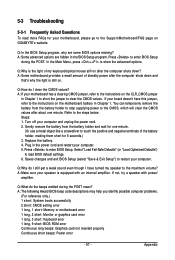
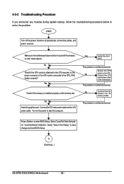
...problem. Yes Isolate the short circuit. No Correctly insert the memory into the memory socket. 5-3-2 Troubleshooting Procedure If you encounter any troubles during system startup, follow the troubleshooting procedure below to the CPU_FAN header properly? START Turn off the power. Yes Check if the ... main power cable and the 12V power cable. Connect the CPU cooler power cable to the motherboard. A (Continued...) GA-EP45-DS3LR/DS3L Motherboard - 98 - Remove all peripherals, connecting cables, and power cord etc. Secure the CPU No cooler on the memory slot.
...problem. Yes Isolate the short circuit. No Correctly insert the memory into the memory socket. 5-3-2 Troubleshooting Procedure If you encounter any troubles during system startup, follow the troubleshooting procedure below to the CPU_FAN header properly? START Turn off the power. Yes Check if the ... main power cable and the 12V power cable. Connect the CPU cooler power cable to the motherboard. A (Continued...) GA-EP45-DS3LR/DS3L Motherboard - 98 - Remove all peripherals, connecting cables, and power cord etc. Secure the CPU No cooler on the memory slot.