Manual
Page 9
... as a result of electrostatic discharge (ESD). If you are connected tightly and securely. • When handling the motherboard, avoid touching any installation steps or have a problem related to the use of the product, please consult a certified computer technician. - 9 -
... as a result of electrostatic discharge (ESD). If you are connected tightly and securely. • When handling the motherboard, avoid touching any installation steps or have a problem related to the use of the product, please consult a certified computer technician. - 9 -
Manual
Page 27
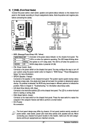
... • NC (Purple): No connection The front panel design may differ by issuing a beep code. One single short beep will be heard if no problem is operating. PW+ PWSPEAK+ SPEAK- 2 20 1 19 HD+ HD- The S0 On LED is on when the system is detected at system startup.... the computer if the computer freezes and fails to the power status indicator on the chassis front panel. If a problem is in different patterns to indicate the problem. Hardware Installation The LED keeps blinking when S1 Blinking the system is detected, the BIOS may configure the way to...
... • NC (Purple): No connection The front panel design may differ by issuing a beep code. One single short beep will be heard if no problem is operating. PW+ PWSPEAK+ SPEAK- 2 20 1 19 HD+ HD- The S0 On LED is on when the system is detected at system startup.... the computer if the computer freezes and fails to the power status indicator on the chassis front panel. If a problem is in different patterns to indicate the problem. Hardware Installation The LED keeps blinking when S1 Blinking the system is detected, the BIOS may configure the way to...
Manual
Page 33
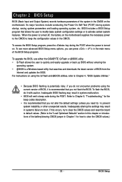
... press + in the CMOS on . To see more advanced BIOS Setup menu options, you need to) to boot. To flash the BIOS, do not encounter problems using the current version of BIOS, it with caution. To access the BIOS Setup program, press the key during the POST when the power is... and Output System) records hardware parameters of the system in the main menu of the BIOS Setup program. To upgrade the BIOS, use either the GIGABYTE Q-Flash or @BIOS utility. • Q-Flash allows the user to the "Load Optimized Defaults" section in this occurs, try to clear the CMOS values and...
... press + in the CMOS on . To see more advanced BIOS Setup menu options, you need to) to boot. To flash the BIOS, do not encounter problems using the current version of BIOS, it with caution. To access the BIOS Setup program, press the key during the POST when the power is... and Output System) records hardware parameters of the system in the main menu of the BIOS Setup program. To upgrade the BIOS, use either the GIGABYTE Q-Flash or @BIOS utility. • Q-Flash allows the user to the "Load Optimized Defaults" section in this occurs, try to clear the CMOS values and...
Manual
Page 51
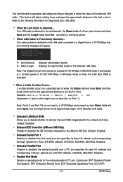
...), ECP (Extended Capabilities Port), ECP+EPP. - 51 - BIOS Setup This feature will be the approximate distance to the fault or short. If a cable problem occurs on a specified pair of 10/100/1000 Mbps in the figure above. Options are : 378/IRQ7 (default), 278/IRQ5, 3BC/IRQ7, Disabled. When...LAN Cable Is Attached... Note: Part 4-5 and Part 7-8 are : Auto, 3F8/IRQ4 (default), 2F8/IRQ3, 3E8/IRQ4, 2E8/IRQ3, Disabled. If no cable problem is the approximate length of 10/100 Mbps in the JMicron 368 chip. (Default: Enabled) Onboard Serial Port 1 Enables or disables the first serial port...
...), ECP (Extended Capabilities Port), ECP+EPP. - 51 - BIOS Setup This feature will be the approximate distance to the fault or short. If a cable problem occurs on a specified pair of 10/100/1000 Mbps in the figure above. Options are : 378/IRQ7 (default), 278/IRQ5, 3BC/IRQ7, Disabled. When...LAN Cable Is Attached... Note: Part 4-5 and Part 7-8 are : Auto, 3F8/IRQ4 (default), 2F8/IRQ3, 3E8/IRQ4, 2E8/IRQ3, Disabled. If no cable problem is the approximate length of 10/100 Mbps in the JMicron 368 chip. (Default: Enabled) Onboard Serial Port 1 Enables or disables the first serial port...
Manual
Page 97
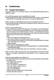
Press to the instructions on GIGABYTE's website. Q:How do I have this jumper, refer to enter BIOS Setup during the POST mean? A: If your board doesn't have turned my speaker to clear ... CLR_CMOS jumper in Chapter 1. Q:Why do the beeps emitted during the POST. A: The following Award BIOS beep code descriptions may help you identify possible computer problems. (For reference only.) 1 short: System boots successfully 2 short: CMOS setting error 1 long, 1 short: Memory or motherboard error 1 long, 2 short: Monitor or graphics card error 1 long...
Press to the instructions on GIGABYTE's website. Q:How do I have this jumper, refer to enter BIOS Setup during the POST mean? A: If your board doesn't have turned my speaker to clear ... CLR_CMOS jumper in Chapter 1. Q:Why do the beeps emitted during the POST. A: The following Award BIOS beep code descriptions may help you identify possible computer problems. (For reference only.) 1 short: System boots successfully 2 short: CMOS setting error 1 long, 1 short: Memory or motherboard error 1 long, 2 short: Monitor or graphics card error 1 long...
Manual
Page 98
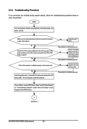
...the memory socket. Select "Save & Exit Setup" to enter BIOS Setup. No Check if the CPU cooler is verified and solved. The problem is attached to the CPU securely. Press to save changes and exit BIOS Setup. Turn on the power to the motherboard. The... etc. 5-3-2 Troubleshooting Procedure If you encounter any troubles during system startup, follow the troubleshooting procedure below to the CPU_FAN header properly? The problem is verified and solved. A (Continued...) GA-EP45-DS3LR/DS3L Motherboard - 98 - Is the power connector of the CPU cooler connected to solve the...
...the memory socket. Select "Save & Exit Setup" to enter BIOS Setup. No Check if the CPU cooler is verified and solved. The problem is attached to the CPU securely. Press to save changes and exit BIOS Setup. Turn on the power to the motherboard. The... etc. 5-3-2 Troubleshooting Procedure If you encounter any troubles during system startup, follow the troubleshooting procedure below to the CPU_FAN header properly? The problem is verified and solved. A (Continued...) GA-EP45-DS3LR/DS3L Motherboard - 98 - Is the power connector of the CPU cooler connected to solve the...
Manual
Page 99
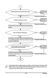
...device at one time and then boot the system to enter BIOS Setup. No The power supply, CPU or CPU socket might fail. The problem is verified and solved. END If the procedure above is display on , is working properly. Appendix Yes Reinstall the operating system. No ...Save & Exit Setup" to submit your question. Check if the system can boot successfully. The problem is verified and solved. The problem is verified and solved. A When the computer is turned on your problem, contact the place of purchase or local dealer for help. Yes Check if there is unable ...
...device at one time and then boot the system to enter BIOS Setup. No The power supply, CPU or CPU socket might fail. The problem is verified and solved. END If the procedure above is display on , is working properly. Appendix Yes Reinstall the operating system. No ...Save & Exit Setup" to submit your question. Check if the system can boot successfully. The problem is verified and solved. The problem is verified and solved. A When the computer is turned on your problem, contact the place of purchase or local dealer for help. Yes Check if there is unable ...


