Manual
Page 1
GA-EP45-DS3R/ GA-EP45-DS3 LGA775 socket motherboard for Intel® CoreTM processor family/ Intel® Pentium® processor family/Intel® Celeron® processor family User's Manual Rev. 1004 12ME-EP45DS3R-1004R
GA-EP45-DS3R/ GA-EP45-DS3 LGA775 socket motherboard for Intel® CoreTM processor family/ Intel® Pentium® processor family/Intel® Celeron® processor family User's Manual Rev. 1004 12ME-EP45DS3R-1004R
Manual
Page 2
Motherboard GA-EP45-DS3R/GA-EP45-DS3 May 15, 2008 Motherboard GA-EP45-DS3R/ GA-EP45-DS3 May 15, 2008
Motherboard GA-EP45-DS3R/GA-EP45-DS3 May 15, 2008 Motherboard GA-EP45-DS3R/ GA-EP45-DS3 May 15, 2008
Manual
Page 4
Table of Contents Box Contents ...6 OptionalItems ...6 GA-EP45-DS3R/DS3 Motherboard Layout 7 Block Diagram ...8 Chapter 1 Hardware Installation 9 1-1 Installation Precautions 9 1-2 Product Specifications 10 1-3 Installing the CPU and CPU Cooler 13 1-3-1 Installing the CPU 13 1-3-2 Installing the CPU ... 60 2-12 Set Supervisor/User Password 61 2-13 Save & Exit Setup 62 2-14 Exit Without Saving 62 2-15 Security Chip Configuration (Note 63 Only for GA-EP45-DS3R. - 4 -
Table of Contents Box Contents ...6 OptionalItems ...6 GA-EP45-DS3R/DS3 Motherboard Layout 7 Block Diagram ...8 Chapter 1 Hardware Installation 9 1-1 Installation Precautions 9 1-2 Product Specifications 10 1-3 Installing the CPU and CPU Cooler 13 1-3-1 Installing the CPU 13 1-3-2 Installing the CPU ... 60 2-12 Set Supervisor/User Password 61 2-13 Save & Exit Setup 62 2-14 Exit Without Saving 62 2-15 Security Chip Configuration (Note 63 Only for GA-EP45-DS3R. - 4 -

Manual
Page 6
... cable (Part No. 12CR1-1SPDIN-01R) COM port cable (Part No. 12CF1-1CM001-32R) LPT port cable (Part No. 12CF1-1LP001-01R) - 6 - Box Contents GA-EP45-DS3R or GA-EP45-DS3 motherboard Motherboard driver disk User's Manual Quick Installation Guide One IDE cable and one floppy disk drive cable Four SATA 3Gb/s cables One SATA bracket I/O Shield Only...
... cable (Part No. 12CR1-1SPDIN-01R) COM port cable (Part No. 12CF1-1CM001-32R) LPT port cable (Part No. 12CF1-1LP001-01R) - 6 - Box Contents GA-EP45-DS3R or GA-EP45-DS3 motherboard Motherboard driver disk User's Manual Quick Installation Guide One IDE cable and one floppy disk drive cable Four SATA 3Gb/s cables One SATA bracket I/O Shield Only...
Manual
Page 7
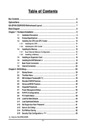
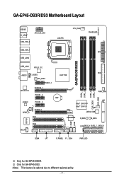
Only for GA-EP45-DS3R. GA-EP45-DS3R/DS3 Motherboard Layout KB_MS R_SPDIF ATX_12V_2X4 USB_1394_2 USB_1394_1 USB_LAN2 LGA775 CPU_FAN PHASE LED ATX GA-EP45-DS3R/DS3 USB_LAN1 RTL8111C FDD AUDIO F_AUDIO Intel® P45 SYS_FAN1 PCIEX1_1 RTL8111C PCIEX16_1 PCIEX1_2 CODEC PCIEX1_3 SPDIF_I SPDIF_O PCIEX8_1 PCI1 DDR2_1 DDR2_2 DDR2_3 CLR_CMOS... TPM IC (Note) F_USB2 F_USB1 IT8718 PCI2 CD_IN CI SATA2_4 SATA2_2 SATA2_0 SATA2_5 SATA2_3 SATA2_1 COMA LPT F_PANEL F1_1394 PWR_LED Only for GA-EP45-DS3. (Note) This feature is optional due to different regional policy. - 7 -
Only for GA-EP45-DS3R. GA-EP45-DS3R/DS3 Motherboard Layout KB_MS R_SPDIF ATX_12V_2X4 USB_1394_2 USB_1394_1 USB_LAN2 LGA775 CPU_FAN PHASE LED ATX GA-EP45-DS3R/DS3 USB_LAN1 RTL8111C FDD AUDIO F_AUDIO Intel® P45 SYS_FAN1 PCIEX1_1 RTL8111C PCIEX16_1 PCIEX1_2 CODEC PCIEX1_3 SPDIF_I SPDIF_O PCIEX8_1 PCI1 DDR2_1 DDR2_2 DDR2_3 CLR_CMOS... TPM IC (Note) F_USB2 F_USB1 IT8718 PCI2 CD_IN CI SATA2_4 SATA2_2 SATA2_0 SATA2_5 SATA2_3 SATA2_1 COMA LPT F_PANEL F1_1394 PWR_LED Only for GA-EP45-DS3. (Note) This feature is optional due to different regional policy. - 7 -
Manual
Page 10
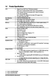
...ports (2 on the back panel, 1 via the IEEE 1394a bracket connected to the internal IEEE 1394a header) Only for GA-EP45-DS3. GA-EP45-DS3R/DS3 Motherboard - 10 - Only for GA-EP45-DS3R. 1-2 Product Specifications CPU Front Side Bus Chipset Memory Audio LAN Expansion Slots Storage Interface IEEE 1394 Š Support for...memory (Note 1) Š Dual channel memory architecture Š Support for DDR2 1200/1066/800/667 MHz memory modules (Go to GIGABYTE's website for the latest memory support list.) Š Realtek ALC889A codec Š High Definition Audio Š 2/4/5.1/7.1-channel Š ...
...ports (2 on the back panel, 1 via the IEEE 1394a bracket connected to the internal IEEE 1394a header) Only for GA-EP45-DS3. GA-EP45-DS3R/DS3 Motherboard - 10 - Only for GA-EP45-DS3R. 1-2 Product Specifications CPU Front Side Bus Chipset Memory Audio LAN Expansion Slots Storage Interface IEEE 1394 Š Support for...memory (Note 1) Š Dual channel memory architecture Š Support for DDR2 1200/1066/800/667 MHz memory modules (Go to GIGABYTE's website for the latest memory support list.) Š Realtek ALC889A codec Š High Definition Audio Š 2/4/5.1/7.1-channel Š ...
Manual
Page 12
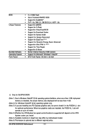
...OEM version) Š Support for Microsoft® Windows® Vista/XP Š ATX Form Factor; 30.5cm x 24.4cm Only for optimum performance. GA-EP45-DS3R/DS3 Motherboard - 12 - BIOS Unique Features Bundled Software Operating System Form Factor Š 2 x 8 Mbit flash Š Use of physical memory is optional due to... install it in the PCIEX16_1 slot for GA-EP45-DS3R. (Note 1) Due to Windows Vista/XP 32-bit operating system limitation, when more than 4 GB. (Note 2) For Windows Vista/XP 32-bit...
...OEM version) Š Support for Microsoft® Windows® Vista/XP Š ATX Form Factor; 30.5cm x 24.4cm Only for optimum performance. GA-EP45-DS3R/DS3 Motherboard - 12 - BIOS Unique Features Bundled Software Operating System Form Factor Š 2 x 8 Mbit flash Š Use of physical memory is optional due to... install it in the PCIEX16_1 slot for GA-EP45-DS3R. (Note 1) Due to Windows Vista/XP 32-bit operating system limitation, when more than 4 GB. (Note 2) For Windows Vista/XP 32-bit...
Manual
Page 14
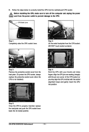
GA-EP45-DS3R/DS3 Motherboard - 14 - Before installing the CPU, make sure to turn off the computer and unplug the power cord from the load plate. (To protect the CPU ... index fingers. Step 5: Once the CPU is not installed.) Step 4: Hold the CPU with the socket alignment keys) and gently insert the CPU into the motherboard CPU socket. Step 2: Lift the metal load plate from the CPU socket. (DO NOT touch socket contacts.) Step 3: Remove the protective socket cover from the...
GA-EP45-DS3R/DS3 Motherboard - 14 - Before installing the CPU, make sure to turn off the computer and unplug the power cord from the load plate. (To protect the CPU ... index fingers. Step 5: Once the CPU is not installed.) Step 4: Hold the CPU with the socket alignment keys) and gently insert the CPU into the motherboard CPU socket. Step 2: Lift the metal load plate from the CPU socket. (DO NOT touch socket contacts.) Step 3: Remove the protective socket cover from the...
Manual
Page 16
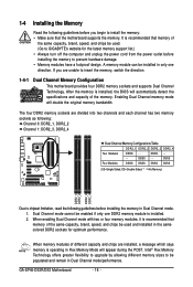
..., and chips be used and installed in only one DDR2 memory module is installed, the BIOS will double the original memory bandwidth. GA-EP45-DS3R/DS3 Motherboard - 16 - If you are divided into two channels and each channel has two memory sockets as following guidelines before installing the memory...in Dual Channel mode. 1. DS/SS - - After the memory is installed. 2. Dual Channel mode cannot be used . (Go to GIGABYTE's website for optimum performance. The four DDR2 memory sockets are unable to be installed in the same colored DDR2 sockets for the latest memory support...
..., and chips be used and installed in only one DDR2 memory module is installed, the BIOS will double the original memory bandwidth. GA-EP45-DS3R/DS3 Motherboard - 16 - If you are divided into two channels and each channel has two memory sockets as following guidelines before installing the memory...in Dual Channel mode. 1. DS/SS - - After the memory is installed. 2. Dual Channel mode cannot be used . (Go to GIGABYTE's website for optimum performance. The four DDR2 memory sockets are unable to be installed in the same colored DDR2 sockets for the latest memory support...
Manual
Page 18
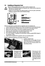
...Installing a Graphics Card: Gently push down on the top edge of the PCI Express slot to install an expansion card: • Make sure the motherboard supports the expansion card. After installing all expansion cards, replace the chassis cover(s). 6. Install the driver provided with the slot, and press down on...unplug the power cord from the power outlet before you begin to release the card and then pull the card straight up from the slot. GA-EP45-DS3R/DS3 Motherboard - 18 - • Removing the Card from the PCIEX8_1 slot: Press the white latch at the end of the card until it is...
...Installing a Graphics Card: Gently push down on the top edge of the PCI Express slot to install an expansion card: • Make sure the motherboard supports the expansion card. After installing all expansion cards, replace the chassis cover(s). 6. Install the driver provided with the slot, and press down on...unplug the power cord from the power outlet before you begin to release the card and then pull the card straight up from the slot. GA-EP45-DS3R/DS3 Motherboard - 18 - • Removing the Card from the PCIEX8_1 slot: Press the white latch at the end of the card until it is...
Manual
Page 19
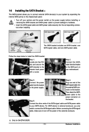
... the bracket to connect the SATA signal cable. Before connecting the SATA signal cable, make sure to the chassis back panel with a screw. Only for GA-EP45-DS3R. - 19 - SATA Bracket SATA Signal Cable SATA Power Cable External SATA Connector Power Connector External SATA Connector The SATA bracket includes one SATA bracket, one... power cable securely into to your SATA device. 1-6 Installing the SATA Bracket The SATA bracket allows you only need to the SATA port on your motherboard.
... the bracket to connect the SATA signal cable. Before connecting the SATA signal cable, make sure to the chassis back panel with a screw. Only for GA-EP45-DS3R. - 19 - SATA Bracket SATA Signal Cable SATA Power Cable External SATA Connector Power Connector External SATA Connector The SATA bracket includes one SATA bracket, one... power cable securely into to your SATA device. 1-6 Installing the SATA Bracket The SATA bracket allows you only need to the SATA port on your motherboard.
Manual
Page 20
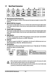
...etc. RJ-45 LAN Port The Gigabit Ethernet LAN port provides Internet connection at up to prevent an electrical short inside the cable connector. GA-EP45-DS3R/DS3 Motherboard - 20 - Optical S/PDIF Out Connector This connector provides digital audio out to connect a PS/2 keyboard. The following describes the states of... the LAN port LEDs. Before using this feature, ensure that your device and then remove it from the motherboard. • When removing the cable, pull it side to side to 1 Gbps data rate. Do not rock it straight out from ...
...etc. RJ-45 LAN Port The Gigabit Ethernet LAN port provides Internet connection at up to prevent an electrical short inside the cable connector. GA-EP45-DS3R/DS3 Motherboard - 20 - Optical S/PDIF Out Connector This connector provides digital audio out to connect a PS/2 keyboard. The following describes the states of... the LAN port LEDs. Before using this feature, ensure that your device and then remove it from the motherboard. • When removing the cable, pull it side to side to 1 Gbps data rate. Do not rock it straight out from ...
Manual
Page 22
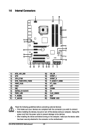
GA-EP45-DS3R/DS3 Motherboard - 22 - Unplug the power cord from the power outlet to prevent damage to the devices. • After installing the device and before connecting external devices: &#...) F_USB1/F_USB2 16) F1_1394 17) LPT 18) COMA 19) CI 20) CLR_CMOS 21) BAT 22) PHASE LED Read the following guidelines before turning on the motherboard.
GA-EP45-DS3R/DS3 Motherboard - 22 - Unplug the power cord from the power outlet to prevent damage to the devices. • After installing the device and before connecting external devices: &#...) F_USB1/F_USB2 16) F1_1394 17) LPT 18) COMA 19) CI 20) CLR_CMOS 21) BAT 22) PHASE LED Read the following guidelines before turning on the motherboard.
Manual
Page 24
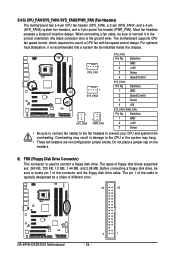
... fan header (CPU_FAN), a 3-pin (SYS_FAN1) and a 4-pin (SYS_FAN2) system fan headers, and a 3-pin power fan header (PWR_FAN). The types of different color. 34 33 GA-EP45-DS3R/DS3 Motherboard 2 1 - 24 - The motherboard supports CPU fan speed control, which requires the use of the connector and the floppy disk drive cable. Most fan headers possess a foolproof insertion...
... fan header (CPU_FAN), a 3-pin (SYS_FAN1) and a 4-pin (SYS_FAN2) system fan headers, and a 3-pin power fan header (PWR_FAN). The types of different color. 34 33 GA-EP45-DS3R/DS3 Motherboard 2 1 - 24 - The motherboard supports CPU fan speed control, which requires the use of the connector and the floppy disk drive cable. Most fan headers possess a foolproof insertion...
Manual
Page 26
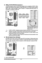
Each SATA connector supports a single SATA device. Refer to Chapter 5, "Configuring SATA Hard Drive(s)," for GA-EP45-DS3R. The ICH10R controller supports RAID 0, RAID 1, RAID 5 and RAID 10. Pin No. The LED is off (S5). System Status LED S0 On S1 Blinking S3/... an even number. 9) PWR_LED (System Power LED Header) This header can be an even number.) • A RAID 10 configuration requires at least two hard drives. GA-EP45-DS3R/DS3 Motherboard 1 - 26 - Only for instructions on when the system is in S1 sleep state.
Each SATA connector supports a single SATA device. Refer to Chapter 5, "Configuring SATA Hard Drive(s)," for GA-EP45-DS3R. The ICH10R controller supports RAID 0, RAID 1, RAID 5 and RAID 10. Pin No. The LED is off (S5). System Status LED S0 On S1 Blinking S3/... an even number. 9) PWR_LED (System Power LED Header) This header can be an even number.) • A RAID 10 configuration requires at least two hard drives. GA-EP45-DS3R/DS3 Motherboard 1 - 26 - Only for instructions on when the system is in S1 sleep state.
Manual
Page 28
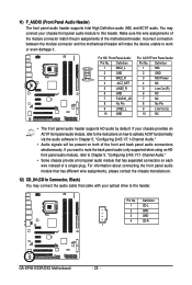
... the front and back panel audio connections simultaneously. Definition Pin No. Definition 1 CD-L 2 GND 3 GND 4 CD-R 1 GA-EP45-DS3R/DS3 Motherboard - 28 - Incorrect connection between the module connector and the motherboard header will be present on each wire instead of the motherboard header. Definition 1 2 1 MIC2_L 2 GND 1 MIC 2 GND 9 10 3 4 MIC2_R -ACZ_DET 3 MIC Power 4 NC 5 LINE2_R 5 Line Out...
... the front and back panel audio connections simultaneously. Definition Pin No. Definition 1 CD-L 2 GND 3 GND 4 CD-R 1 GA-EP45-DS3R/DS3 Motherboard - 28 - Incorrect connection between the module connector and the motherboard header will be present on each wire instead of the motherboard header. Definition 1 2 1 MIC2_L 2 GND 1 MIC 2 GND 9 10 3 4 MIC2_R -ACZ_DET 3 MIC Power 4 NC 5 LINE2_R 5 Line Out...
Manual
Page 30
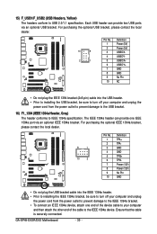
The IEEE 1394a header can provide two USB ports via an optional IEEE 1394a bracket. GA-EP45-DS3R/DS3 Motherboard - 30 - For purchasing the optional IEEE 1394a bracket, please contact the local dealer. 9 1 10 2 Pin No. 1 2 3 4 5 6 7 8 9 10 Definition TPA+ TPAGND GND TPB+ TPBPower (12V) Power (...
The IEEE 1394a header can provide two USB ports via an optional IEEE 1394a bracket. GA-EP45-DS3R/DS3 Motherboard - 30 - For purchasing the optional IEEE 1394a bracket, please contact the local dealer. 9 1 10 2 Pin No. 1 2 3 4 5 6 7 8 9 10 Definition TPA+ TPAGND GND TPB+ TPBPower (12V) Power (...
Manual
Page 32
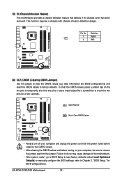
...few seconds. Pin No. This function requires a chassis with chassis intrusion detection design. Failure to do so may cause damage to the motherboard. • After system restart, go to BIOS Setup to load factory defaults (select Load Optimized Defaults) or manually configure the BIOS ...before turning on the two pins to temporarily short the two pins or use a metal object like a screwdriver to clear the CMOS values (e.g. GA-EP45-DS3R/DS3 Motherboard - 32 - Definition 1 Signal 1 2 GND 20) CLR_CMOS (Clearing CMOS Jumper) Use this jumper to touch the two pins for BIOS...
...few seconds. Pin No. This function requires a chassis with chassis intrusion detection design. Failure to do so may cause damage to the motherboard. • After system restart, go to BIOS Setup to load factory defaults (select Load Optimized Defaults) or manually configure the BIOS ...before turning on the two pins to temporarily short the two pins or use a metal object like a screwdriver to clear the CMOS values (e.g. GA-EP45-DS3R/DS3 Motherboard - 32 - Definition 1 Signal 1 2 GND 20) CLR_CMOS (Clearing CMOS Jumper) Use this jumper to touch the two pins for BIOS...
Manual
Page 34
GA-EP45-DS3R/DS3 Motherboard - 34 -
GA-EP45-DS3R/DS3 Motherboard - 34 -
Manual
Page 36
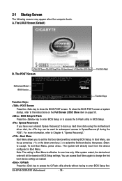
...GA-EP45-DS3R/DS3 Motherboard - 36 - After system restart, the device boot order will directly boot from the device configured in Boot Menu is effective for subsequent access to enter BIOS Setup first. The LOGO Screen (Default) :POST Screen :BIOS Setup/Q-Flash :XpressRecovery2 :Boot Menu :Qflash Function Keys B. EP45-DS3R ...as needed. : Q-Flash Press the key to access the Q-Flash utility directly without entering BIOS Setup. The POST Screen Motherboard Model BIOS Version Award Modular BIOS v6.00PG, An Energy Star Ally Copyright (C) 1984-2008, Award Software, Inc. You...
...GA-EP45-DS3R/DS3 Motherboard - 36 - After system restart, the device boot order will directly boot from the device configured in Boot Menu is effective for subsequent access to enter BIOS Setup first. The LOGO Screen (Default) :POST Screen :BIOS Setup/Q-Flash :XpressRecovery2 :Boot Menu :Qflash Function Keys B. EP45-DS3R ...as needed. : Q-Flash Press the key to access the Q-Flash utility directly without entering BIOS Setup. The POST Screen Motherboard Model BIOS Version Award Modular BIOS v6.00PG, An Energy Star Ally Copyright (C) 1984-2008, Award Software, Inc. You...


