Manual
Page 1
GA-EP45-DS3R/ GA-EP45-DS3 LGA775 socket motherboard for Intel® CoreTM processor family/ Intel® Pentium® processor family/Intel® Celeron® processor family User's Manual Rev. 1004 12ME-EP45DS3R-1004R
GA-EP45-DS3R/ GA-EP45-DS3 LGA775 socket motherboard for Intel® CoreTM processor family/ Intel® Pentium® processor family/Intel® Celeron® processor family User's Manual Rev. 1004 12ME-EP45DS3R-1004R
Manual
Page 2
Motherboard GA-EP45-DS3R/GA-EP45-DS3 May 15, 2008 Motherboard GA-EP45-DS3R/ GA-EP45-DS3 May 15, 2008
Motherboard GA-EP45-DS3R/GA-EP45-DS3 May 15, 2008 Motherboard GA-EP45-DS3R/ GA-EP45-DS3 May 15, 2008
Manual
Page 3
... detailed product information, carefully read the User's Manual. „ For instructions on how to use GIGABYTE's unique features, read or download the information on/from the Support\Motherboard\Technology Guide page on your motherboard revision before updating motherboard BIOS, drivers, or when looking for technical information. Disclaimer Information in any form or by any...
... detailed product information, carefully read the User's Manual. „ For instructions on how to use GIGABYTE's unique features, read or download the information on/from the Support\Motherboard\Technology Guide page on your motherboard revision before updating motherboard BIOS, drivers, or when looking for technical information. Disclaimer Information in any form or by any...
Manual
Page 4
Table of Contents Box Contents ...6 OptionalItems ...6 GA-EP45-DS3R/DS3 Motherboard Layout 7 Block Diagram ...8 Chapter 1 Hardware Installation 9 1-1 Installation Precautions 9 1-2 Product Specifications 10 1-3 Installing the CPU and CPU Cooler 13 1-3-1 Installing the CPU 13 1-3-2 Installing the CPU ... 60 2-12 Set Supervisor/User Password 61 2-13 Save & Exit Setup 62 2-14 Exit Without Saving 62 2-15 Security Chip Configuration (Note 63 Only for GA-EP45-DS3R. - 4 -
Table of Contents Box Contents ...6 OptionalItems ...6 GA-EP45-DS3R/DS3 Motherboard Layout 7 Block Diagram ...8 Chapter 1 Hardware Installation 9 1-1 Installation Precautions 9 1-2 Product Specifications 10 1-3 Installing the CPU and CPU Cooler 13 1-3-1 Installing the CPU 13 1-3-2 Installing the CPU ... 60 2-12 Set Supervisor/User Password 61 2-13 Save & Exit Setup 62 2-14 Exit Without Saving 62 2-15 Security Chip Configuration (Note 63 Only for GA-EP45-DS3R. - 4 -

Manual
Page 6
The box contents are for reference only. Box Contents GA-EP45-DS3R or GA-EP45-DS3 motherboard Motherboard driver disk User's Manual Quick Installation Guide One IDE cable and one floppy disk drive cable Four SATA 3Gb/s cables One SATA bracket I/O Shield Only for GA-EP45-DS3R. • The box contents above are subject to change without notice. • The...
The box contents are for reference only. Box Contents GA-EP45-DS3R or GA-EP45-DS3 motherboard Motherboard driver disk User's Manual Quick Installation Guide One IDE cable and one floppy disk drive cable Four SATA 3Gb/s cables One SATA bracket I/O Shield Only for GA-EP45-DS3R. • The box contents above are subject to change without notice. • The...
Manual
Page 7
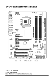
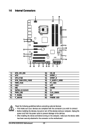
GA-EP45-DS3R/DS3 Motherboard Layout KB_MS R_SPDIF ATX_12V_2X4 USB_1394_2 USB_1394_1 USB_LAN2 LGA775 CPU_FAN PHASE LED ATX GA-EP45-DS3R/DS3 USB_LAN1 RTL8111C FDD AUDIO F_AUDIO Intel® P45 SYS_FAN1 PCIEX1_1 RTL8111C PCIEX16_1 PCIEX1_2 CODEC PCIEX1_3 SPDIF_I SPDIF_O PCIEX8_1 PCI1 DDR2_1 DDR2_2 DDR2_3 CLR_CMOS DDR2_4... B_BIOS TPM IC (Note) F_USB2 F_USB1 IT8718 PCI2 CD_IN CI SATA2_4 SATA2_2 SATA2_0 SATA2_5 SATA2_3 SATA2_1 COMA LPT F_PANEL F1_1394 PWR_LED Only for GA-EP45-DS3. (Note) This feature is optional due to different regional policy. - 7 - Only for...
GA-EP45-DS3R/DS3 Motherboard Layout KB_MS R_SPDIF ATX_12V_2X4 USB_1394_2 USB_1394_1 USB_LAN2 LGA775 CPU_FAN PHASE LED ATX GA-EP45-DS3R/DS3 USB_LAN1 RTL8111C FDD AUDIO F_AUDIO Intel® P45 SYS_FAN1 PCIEX1_1 RTL8111C PCIEX16_1 PCIEX1_2 CODEC PCIEX1_3 SPDIF_I SPDIF_O PCIEX8_1 PCI1 DDR2_1 DDR2_2 DDR2_3 CLR_CMOS DDR2_4... B_BIOS TPM IC (Note) F_USB2 F_USB1 IT8718 PCI2 CD_IN CI SATA2_4 SATA2_2 SATA2_0 SATA2_5 SATA2_3 SATA2_1 COMA LPT F_PANEL F1_1394 PWR_LED Only for GA-EP45-DS3. (Note) This feature is optional due to different regional policy. - 7 - Only for...

Manual
Page 9
...that all cables and power connectors of your hardware components are connected. • To prevent damage to the motherboard, do not remove or break motherboard S/N (Serial Number) sticker or warranty sticker provided by unplugging the power cord from the power outlet before ...of the product, please consult a certified computer technician. - 9 - These stickers are connected tightly and securely. • When handling the motherboard, avoid touching any installation steps or have a problem related to the use of electrostatic discharge (ESD). Prior to installation, carefully read the ...
...that all cables and power connectors of your hardware components are connected. • To prevent damage to the motherboard, do not remove or break motherboard S/N (Serial Number) sticker or warranty sticker provided by unplugging the power cord from the power outlet before ...of the product, please consult a certified computer technician. - 9 - These stickers are connected tightly and securely. • When handling the motherboard, avoid touching any installation steps or have a problem related to the use of electrostatic discharge (ESD). Prior to installation, carefully read the ...
Manual
Page 10
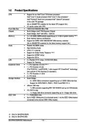
...® Pentium® Dual-Core processor/Intel® Celeron® processor in the LGA 775 package (Go to GIGABYTE's website for the latest CPU support list.) Š L2 cache varies with CPU Š 1600/1333/1066/800...1) Š Dual channel memory architecture Š Support for DDR2 1200/1066/800/667 MHz memory modules (Go to GIGABYTE's website for the latest memory support list.) Š Realtek ALC889A codec Š High Definition Audio Š 2/4/5.1/7.1-channel ...the IEEE 1394a bracket connected to the internal IEEE 1394a header) Only for GA-EP45-DS3. GA-EP45-DS3R/DS3 Motherboard - 10 -
...® Pentium® Dual-Core processor/Intel® Celeron® processor in the LGA 775 package (Go to GIGABYTE's website for the latest CPU support list.) Š L2 cache varies with CPU Š 1600/1333/1066/800...1) Š Dual channel memory architecture Š Support for DDR2 1200/1066/800/667 MHz memory modules (Go to GIGABYTE's website for the latest memory support list.) Š Realtek ALC889A codec Š High Definition Audio Š 2/4/5.1/7.1-channel ...the IEEE 1394a bracket connected to the internal IEEE 1394a header) Only for GA-EP45-DS3. GA-EP45-DS3R/DS3 Motherboard - 10 -
Manual
Page 12
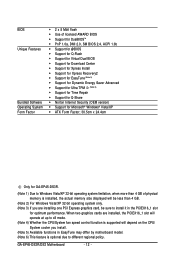
... (OEM version) Š Support for Microsoft® Windows® Vista/XP Š ATX Form Factor; 30.5cm x 24.4cm Only for GA-EP45-DS3R. (Note 1) Due to Windows Vista/XP 32-bit operating system limitation, when more than 4 GB of physical memory is installed, the actual...install. (Note 5) Available functions in EasyTune may differ by motherboard model. (Note 6) This feature is supported will operate at up to x8 mode. (Note 4) Whether the CPU/System fan speed control function is optional due to install it in the PCIEX16_1 slot for optimum performance. GA-EP45-DS3R/DS3 Motherboard - 12 -
... (OEM version) Š Support for Microsoft® Windows® Vista/XP Š ATX Form Factor; 30.5cm x 24.4cm Only for GA-EP45-DS3R. (Note 1) Due to Windows Vista/XP 32-bit operating system limitation, when more than 4 GB of physical memory is installed, the actual...install. (Note 5) Available functions in EasyTune may differ by motherboard model. (Note 6) This feature is supported will operate at up to x8 mode. (Note 4) Whether the CPU/System fan speed control function is optional due to install it in the PCIEX16_1 slot for optimum performance. GA-EP45-DS3R/DS3 Motherboard - 12 -

Manual
Page 13
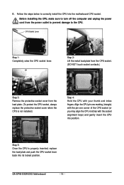
..., please do so according to prevent hardware damage. • Locate the pin one of the CPU. Locate the alignment keys on the motherboard CPU socket and the notches on the computer if the CPU cooler is not recom- Hardware Installation mended that the system bus frequency be... inserted if oriented incorrectly. (Or you begin to install the CPU: • Make sure that the motherboard supports the CPU. (Go to GIGABYTE's website for the peripherals. The CPU cannot be set the frequency beyond hardware specifications since it does not meet the standard ...
..., please do so according to prevent hardware damage. • Locate the pin one of the CPU. Locate the alignment keys on the motherboard CPU socket and the notches on the computer if the CPU cooler is not recom- Hardware Installation mended that the system bus frequency be... inserted if oriented incorrectly. (Or you begin to install the CPU: • Make sure that the motherboard supports the CPU. (Go to GIGABYTE's website for the peripherals. The CPU cannot be set the frequency beyond hardware specifications since it does not meet the standard ...
Manual
Page 14
... socket. Step 5: Once the CPU is not installed.) Step 4: Hold the CPU with the socket alignment keys) and gently insert the CPU into position. GA-EP45-DS3R/DS3 Motherboard - 14 - Align the CPU pin one marking (triangle) with the pin one corner of the CPU socket (or you may align the CPU notches with...
... socket. Step 5: Once the CPU is not installed.) Step 4: Hold the CPU with the socket alignment keys) and gently insert the CPU into position. GA-EP45-DS3R/DS3 Motherboard - 14 - Align the CPU pin one marking (triangle) with the pin one corner of the CPU socket (or you may align the CPU notches with...
Manual
Page 15
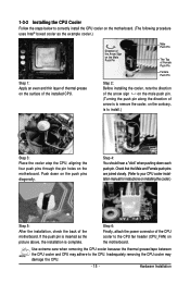
...is complete. Hardware Installation Step 4: You should hear a "click" when pushing down on the motherboard. Inadequately removing the CPU cooler may adhere to your CPU cooler installation manual for instructions on the motherboard. Check that the Male and Female push pins are joined closely. (Refer to the CPU.... the contrary, is inserted as the example cooler.) Step 1: Apply an even and thin layer of thermal grease on the surface of the motherboard. Use extreme care when removing the CPU cooler because the thermal grease/tape between the CPU cooler and CPU may damage the CPU. - ...
...is complete. Hardware Installation Step 4: You should hear a "click" when pushing down on the motherboard. Inadequately removing the CPU cooler may adhere to your CPU cooler installation manual for instructions on the motherboard. Check that the Male and Female push pins are joined closely. (Refer to the CPU.... the contrary, is inserted as the example cooler.) Step 1: Apply an even and thin layer of thermal grease on the surface of the motherboard. Use extreme care when removing the CPU cooler because the thermal grease/tape between the CPU cooler and CPU may damage the CPU. - ...
Manual
Page 16
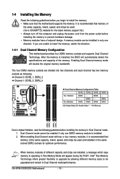
... When enabling Dual Channel mode with two or four memory modules, it is recommended that the motherboard supports the memory. Enabling Dual Channel memory mode will appear during the POST. GA-EP45-DS3R/DS3 Motherboard - 16 - A memory module can be installed in only one DDR2 memory module is operating ...in Flex Memory Mode will double the original memory bandwidth. When memory modules of the same capacity, brand, speed, and chips be used . (Go to GIGABYTE's...
... When enabling Dual Channel mode with two or four memory modules, it is recommended that the motherboard supports the memory. Enabling Dual Channel memory mode will appear during the POST. GA-EP45-DS3R/DS3 Motherboard - 16 - A memory module can be installed in only one DDR2 memory module is operating ...in Flex Memory Mode will double the original memory bandwidth. When memory modules of the same capacity, brand, speed, and chips be used . (Go to GIGABYTE's...
Manual
Page 17
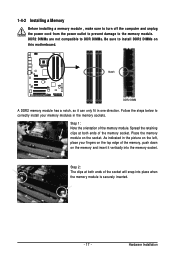
... insert it can only fit in the picture on the left, place your memory modules in the memory sockets. Place the memory module on this motherboard. Hardware Installation DDR2 DIMMs are not compatible to DDR DIMMs. Be sure to install DDR2 DIMMs on the socket. As indicated in one direction.
... insert it can only fit in the picture on the left, place your memory modules in the memory sockets. Place the memory module on this motherboard. Hardware Installation DDR2 DIMMs are not compatible to DDR DIMMs. Be sure to install DDR2 DIMMs on the socket. As indicated in one direction.
Manual
Page 18
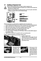
... PCI Express x16 Slot PCI Express x8 Slot PCI Slot Follow the steps below to install an expansion card: • Make sure the motherboard supports the expansion card. GA-EP45-DS3R/DS3 Motherboard - 18 - • Removing the Card from the PCIEX8_1 slot: Press the white latch at the end of the card until it is...
... PCI Express x16 Slot PCI Express x8 Slot PCI Slot Follow the steps below to install an expansion card: • Make sure the motherboard supports the expansion card. GA-EP45-DS3R/DS3 Motherboard - 18 - • Removing the Card from the PCIEX8_1 slot: Press the white latch at the end of the card until it is...
Manual
Page 19
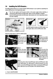
... the SATA signal cable, make sure to hardware. • Insert the SATA signal cable and SATA power cable securely into to your motherboard. SATA Bracket SATA Signal Cable SATA Power Cable External SATA Connector Power Connector External SATA Connector The SATA bracket includes one SATA bracket, ...the internal SATA port(s) to the chassis back panel. • Turn off your system and the power switch on Step 5: the bracket. Only for GA-EP45-DS3R. - 19 - Follow the steps below to install the SATA bracket: Step 1: Locate one SATA power cable. Step 2: Connect the SATA ...
... the SATA signal cable, make sure to hardware. • Insert the SATA signal cable and SATA power cable securely into to your motherboard. SATA Bracket SATA Signal Cable SATA Power Cable External SATA Connector Power Connector External SATA Connector The SATA bracket includes one SATA bracket, ...the internal SATA port(s) to the chassis back panel. • Turn off your system and the power switch on Step 5: the bracket. Only for GA-EP45-DS3R. - 19 - Follow the steps below to install the SATA bracket: Step 1: Locate one SATA power cable. Step 2: Connect the SATA ...
Manual
Page 20
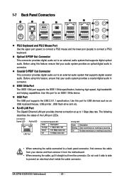
...-45 LAN Port The Gigabit Ethernet LAN port provides Internet connection at up to an external audio system that supports digital optical audio. GA-EP45-DS3R/DS3 Motherboard - 20 - Coaxial S/PDIF Out Connector This connector provides digital audio out to connect a PS/2 keyboard. The following describes the states... USB keyboard/mouse, USB printer, USB flash drive and etc. Use this feature, ensure that your device and then remove it from the motherboard. • When removing the cable, pull it side to side to a back panel connector, first remove the cable from the connector....
...-45 LAN Port The Gigabit Ethernet LAN port provides Internet connection at up to an external audio system that supports digital optical audio. GA-EP45-DS3R/DS3 Motherboard - 20 - Coaxial S/PDIF Out Connector This connector provides digital audio out to connect a PS/2 keyboard. The following describes the states... USB keyboard/mouse, USB printer, USB flash drive and etc. Use this feature, ensure that your device and then remove it from the motherboard. • When removing the cable, pull it side to side to a back panel connector, first remove the cable from the connector....
Manual
Page 22
GA-EP45-DS3R/DS3 Motherboard - 22 - Unplug the power cord from the power outlet to prevent damage to the devices. • After installing the device and before connecting external devices: &#..., make sure your devices are compliant with the connectors you wish to connect. • Before installing the devices, be sure to the connector on the motherboard.
GA-EP45-DS3R/DS3 Motherboard - 22 - Unplug the power cord from the power outlet to prevent damage to the devices. • After installing the device and before connecting external devices: &#..., make sure your devices are compliant with the connectors you wish to connect. • Before installing the devices, be sure to the connector on the motherboard.

Manual
Page 23
... using a power supply providing a 2x4 12V and power connector, remove the protective covers from the 12V power connector and the main power connector on the motherboard. Do not insert the power supply cables into pins under the protective covers when using an Intel Extreme Edition CPU (130W). • To meet expansion... for 2x12-pin ATX) - 23 - Before connecting the power connector, first make sure the power supply is turned off and all the components on the motherboard.
... using a power supply providing a 2x4 12V and power connector, remove the protective covers from the 12V power connector and the main power connector on the motherboard. Do not insert the power supply cables into pins under the protective covers when using an Intel Extreme Edition CPU (130W). • To meet expansion... for 2x12-pin ATX) - 23 - Before connecting the power connector, first make sure the power supply is turned off and all the components on the motherboard.
Manual
Page 24
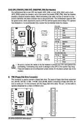
...+12V 3 Sense • Be sure to connect fan cables to the fan headers to connect a floppy disk drive. The types of different color. 34 33 GA-EP45-DS3R/DS3 Motherboard 2 1 - 24 - Most fan headers possess a foolproof insertion design. For optimum heat dissipation, it in damage to connect it is typically designated by a ... system may result in the correct orientation (the black connector wire is used to prevent your CPU and system from overheating. The motherboard supports CPU fan speed control, which requires the use of the connector and the floppy disk drive cable.
...+12V 3 Sense • Be sure to connect fan cables to the fan headers to connect a floppy disk drive. The types of different color. 34 33 GA-EP45-DS3R/DS3 Motherboard 2 1 - 24 - Most fan headers possess a foolproof insertion design. For optimum heat dissipation, it in damage to connect it is typically designated by a ... system may result in the correct orientation (the black connector wire is used to prevent your CPU and system from overheating. The motherboard supports CPU fan speed control, which requires the use of the connector and the floppy disk drive cable.


