Manual
Page 3
... The revision number on your motherboard revision before updating motherboard BIOS, drivers, or when looking for technical information. Check your motherboard looks like this manual are legally registered to assist in the use GIGABYTE's unique features, read the Quick Installation Guide included with the...and features in this manual may be made by copyright laws and is 1.0. Disclaimer Information in this manual is protected by GIGABYTE without GIGABYTE's prior written permission. The trademarks mentioned in any form or by any means without prior notice. Changes to use of...
... The revision number on your motherboard revision before updating motherboard BIOS, drivers, or when looking for technical information. Check your motherboard looks like this manual are legally registered to assist in the use GIGABYTE's unique features, read the Quick Installation Guide included with the...and features in this manual may be made by copyright laws and is 1.0. Disclaimer Information in this manual is protected by GIGABYTE without GIGABYTE's prior written permission. The trademarks mentioned in any form or by any means without prior notice. Changes to use of...
Manual
Page 4
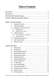
Table of Contents Box Contents...6 Optional Items...6 GA-EP43T-USB3 Motherboard Layout 7 GA-EP43T-USB3 Motherboard Block Diagram 8 Chapter 1 Hardware Installation 9 1-1 Installation Precautions 9 1-2 Product Specifications 10 1-3 Installing the CPU and CPU... an Expansion Card 18 1-6 Back Panel Connectors 19 1-7 Internal Connectors 21 Chapter 2 BIOS Setup 31 2-1 Startup Screen 32 2-2 The Main Menu 33 2-3 MB Intelligent Tweaker(M.I.T 35 2-4 Standard CMOS Features 43 2-5 Advanced BIOS Features 45 2-6 Integrated Peripherals 48 2-7 Power Management Setup 51 2-8 PnP/PCI Configurations...
Table of Contents Box Contents...6 Optional Items...6 GA-EP43T-USB3 Motherboard Layout 7 GA-EP43T-USB3 Motherboard Block Diagram 8 Chapter 1 Hardware Installation 9 1-1 Installation Precautions 9 1-2 Product Specifications 10 1-3 Installing the CPU and CPU... an Expansion Card 18 1-6 Back Panel Connectors 19 1-7 Internal Connectors 21 Chapter 2 BIOS Setup 31 2-1 Startup Screen 32 2-2 The Main Menu 33 2-3 MB Intelligent Tweaker(M.I.T 35 2-4 Standard CMOS Features 43 2-5 Advanced BIOS Features 45 2-6 Integrated Peripherals 48 2-7 Power Management Setup 51 2-8 PnP/PCI Configurations...
Manual
Page 5
... 60 3-4 Contact...61 3-5 System...61 3-6 Download Center 62 3-7 New Utilities...62 Chapter 4 Unique Features 63 4-1 Xpress Recovery2 63 4-2 BIOS Update Utilities 66 4-2-1 Updating the BIOS with the Q-Flash Utility 66 4-2-2 Updating the BIOS with the @BIOS Utility 69 4-3 EasyTune 6...70 4-4 Dynamic Energy Saver Advanced 71 4-5 Q-Share...73 4-6 SMART Recovery 74 4-7 Auto Green...75 Chapter...
... 60 3-4 Contact...61 3-5 System...61 3-6 Download Center 62 3-7 New Utilities...62 Chapter 4 Unique Features 63 4-1 Xpress Recovery2 63 4-2 BIOS Update Utilities 66 4-2-1 Updating the BIOS with the Q-Flash Utility 66 4-2-2 Updating the BIOS with the @BIOS Utility 69 4-3 EasyTune 6...70 4-4 Dynamic Energy Saver Advanced 71 4-5 Q-Share...73 4-6 SMART Recovery 74 4-7 Auto Green...75 Chapter...
Manual
Page 8
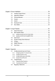
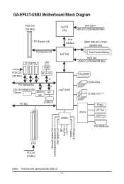
GA-EP43T-USB3 Motherboard Block Diagram PCIe CLK (100 MHz) LGA775 CPU CPU CLK+/(400 (O.C.)/333/266/200 MHz) 1 PCI Express x16 PCI Express x16 3 PCI Express x1 ... 3.0 Host Interface DDR3 1600 (O.C.)/1333/ 1066/800 MHz Intel® P43 Dual Channel Memory MCH CLK (400(O.C.)/333/266/200 MHz) Intel® ICH10 Dual BIOS 6 SATA 3Gb/s 12 USB 2.0/1.1(Note) CODEC IT8718 Floppy LPT Port COM Port PS/2 KB/Mouse Surround Speaker Out Center/Subwoofer Speaker Out Side Speaker Out...
GA-EP43T-USB3 Motherboard Block Diagram PCIe CLK (100 MHz) LGA775 CPU CPU CLK+/(400 (O.C.)/333/266/200 MHz) 1 PCI Express x16 PCI Express x16 3 PCI Express x1 ... 3.0 Host Interface DDR3 1600 (O.C.)/1333/ 1066/800 MHz Intel® P43 Dual Channel Memory MCH CLK (400(O.C.)/333/266/200 MHz) Intel® ICH10 Dual BIOS 6 SATA 3Gb/s 12 USB 2.0/1.1(Note) CODEC IT8718 Floppy LPT Port COM Port PS/2 KB/Mouse Surround Speaker Out Center/Subwoofer Speaker Out Side Speaker Out...

Manual
Page 11
... 3.0 ports 1 x RJ-45 port 6 x audio jacks (Center/Subwoofer Speaker Out/Rear Speaker Out/ Side Speaker Out/Line In/Line Out/Microphone) I/O w iTE IT8718 Hardware Monitor w w w w w w BIOS w w w w System voltage detection CPU/System temperature detection CPU/System/Power fan speed detection CPU overheating warning CPU/System/Power fan fail warning CPU/System fan...
... 3.0 ports 1 x RJ-45 port 6 x audio jacks (Center/Subwoofer Speaker Out/Rear Speaker Out/ Side Speaker Out/Line In/Line Out/Microphone) I/O w iTE IT8718 Hardware Monitor w w w w w w BIOS w w w w System voltage detection CPU/System temperature detection CPU/System/Power fan speed detection CPU overheating warning CPU/System/Power fan fail warning CPU/System fan...
Manual
Page 12
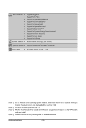
Unique Features w w w w w w w w w w w Bundled Software w Support for @BIOS Support for Q-Flash Support for Xpress BIOS Rescue Support for Download Center Support for Xpress Install Support for Xpress Recovery2 Support for EasyTune (Note 4) Support for Dynamic Energy Saver Advanced Support for ...
Unique Features w w w w w w w w w w w Bundled Software w Support for @BIOS Support for Q-Flash Support for Xpress BIOS Rescue Support for Download Center Support for Xpress Install Support for Xpress Recovery2 Support for EasyTune (Note 4) Support for Dynamic Energy Saver Advanced Support for ...
Manual
Page 16
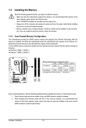
...direction. Hardware Installation - 16 - After the memory is recommended that the motherboard supports the memory. DS/SS - - A memory module can be used . (Go to GIGABYTE's website for optimum performance. 1-4 Installing the Memory Read the following guidelines before installing the memory to insert the memory, switch the direction. 1-4-1 Dual Channel Memory...following : Channel 0: DDR3_1, DDR3_2 Channel 1: DDR3_3, DDR3_4 Dual Channel Memory Configurations Table DDR3_1 DDR3_2 DDR3_3 DDR3_4 Two Modules DS/SS - - It is installed, the BIOS will double the original memory bandwidth.
...direction. Hardware Installation - 16 - After the memory is recommended that the motherboard supports the memory. DS/SS - - A memory module can be used . (Go to GIGABYTE's website for optimum performance. 1-4 Installing the Memory Read the following guidelines before installing the memory to insert the memory, switch the direction. 1-4-1 Dual Channel Memory...following : Channel 0: DDR3_1, DDR3_2 Channel 1: DDR3_3, DDR3_4 Dual Channel Memory Configurations Table DDR3_1 DDR3_2 DDR3_3 DDR3_4 Two Modules DS/SS - - It is installed, the BIOS will double the original memory bandwidth.
Manual
Page 18
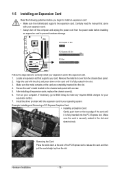
Remove the metal slot cover from the slot. If necessary, go to BIOS Setup to correctly install your expansion card in your operating system. Make sure the card is securely seated in the slot and does not rock. &#...: Gently push down on your expansion card(s). 7. PCI Express x1 Slot PCI Express x16 Slot PCI Slot Follow the steps below to make any required BIOS changes for your computer.
Remove the metal slot cover from the slot. If necessary, go to BIOS Setup to correctly install your expansion card in your operating system. Make sure the card is securely seated in the slot and does not rock. &#...: Gently push down on your expansion card(s). 7. PCI Express x1 Slot PCI Express x16 Slot PCI Slot Follow the steps below to make any required BIOS changes for your computer.

Manual
Page 25
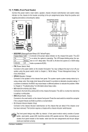
... removing the battery: 1. Danger of the battery holder, making them short for 5 seconds.) 3. 9) BAT (Battery) The battery provides power to keep the values (such as BIOS configurations, date, and time information) in accordance with local environmental regulations. 10) CD_IN (CD In Connector) You may connect the audio cable that came with...
... removing the battery: 1. Danger of the battery holder, making them short for 5 seconds.) 3. 9) BAT (Battery) The battery provides power to keep the values (such as BIOS configurations, date, and time information) in accordance with local environmental regulations. 10) CD_IN (CD In Connector) You may connect the audio cable that came with...
Manual
Page 26
... MSG/PWR (Message/Power/Sleep LED, Yellow/Purple): System Status LED Connects to the power status indicator on when the system is detected, the BIOS may differ by issuing a beep code. If a problem is operating. This function requires a chassis with a chassis intrusion switch/sensor. Message/Power... reset switch, power LED, hard drive activity LED, speaker and etc. When connecting your system using the power switch (refer to Chapter 2, "BIOS Setup," "Power Management Setup," for information about beep codes. • HD (Hard Drive Activity LED, Blue) Connects to the hard drive activity...
... MSG/PWR (Message/Power/Sleep LED, Yellow/Purple): System Status LED Connects to the power status indicator on when the system is detected, the BIOS may differ by issuing a beep code. If a problem is operating. This function requires a chassis with a chassis intrusion switch/sensor. Message/Power... reset switch, power LED, hard drive activity LED, speaker and etc. When connecting your system using the power switch (refer to Chapter 2, "BIOS Setup," "Power Management Setup," for information about beep codes. • HD (Hard Drive Activity LED, Blue) Connects to the hard drive activity...
Manual
Page 30
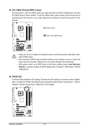
...the power cord from the jumper. To enable the PHASE LED display function, please first enable Dynamic Energy Saver™ . date information and BIOS configurations) and reset the CMOS values to Chapter 4, "Dynamic Energy Saver™ Advanced," for more the number of lighted LEDs. Failure to... before turning on the two pins to temporarily short the two pins or use a metal object like a screwdriver to touch the two pins for BIOS configurations). 19) PHASE LED The Phase LEDs indicate the CPU loading. Hardware Installation - 30 - Refer to factory defaults. 18) CLR_CMOS (Clearing ...
...the power cord from the jumper. To enable the PHASE LED display function, please first enable Dynamic Energy Saver™ . date information and BIOS configurations) and reset the CMOS values to Chapter 4, "Dynamic Energy Saver™ Advanced," for more the number of lighted LEDs. Failure to... before turning on the two pins to temporarily short the two pins or use a metal object like a screwdriver to touch the two pins for BIOS configurations). 19) PHASE LED The Phase LEDs indicate the CPU loading. Hardware Installation - 30 - Refer to factory defaults. 18) CLR_CMOS (Clearing ...
Manual
Page 31
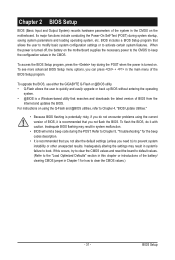
... default settings (unless you do it is a Windows-based utility that searches and downloads the latest version of BIOS from the Internet and updates the BIOS. To upgrade the BIOS, use either the GIGABYTE Q-Flash or @BIOS utility. • Q-Flash allows the user to prevent system instability or other unexpected results. For instructions on the...
... default settings (unless you do it is a Windows-based utility that searches and downloads the latest version of BIOS from the Internet and updates the BIOS. To upgrade the BIOS, use either the GIGABYTE Q-Flash or @BIOS utility. • Q-Flash allows the user to prevent system instability or other unexpected results. For instructions on the...
Manual
Page 32
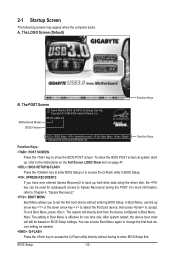
... utility in Boot Menu is effective for subsequent access to access the Q-Flash utility directly without entering BIOS Setup. BIOS Setup - 32 - The system will still be used for one time only. Motherboard Model BIOS Version EP43T-USB3 E4 . . . . : BIOS Setup : XpressRecovery2 : Boot Menu : Qflash 11/26/2009-P43-ICH10-6A79PG0AC-00 Function Keys Function Keys...
... utility in Boot Menu is effective for subsequent access to access the Q-Flash utility directly without entering BIOS Setup. BIOS Setup - 32 - The system will still be used for one time only. Motherboard Model BIOS Version EP43T-USB3 E4 . . . . : BIOS Setup : XpressRecovery2 : Boot Menu : Qflash 11/26/2009-P43-ICH10-6A79PG0AC-00 Function Keys Function Keys...

Manual
Page 33
...to select an item Execute command or enter the submenu Main Menu: Exit the BIOS Setup program Submenus: Exit current submenu Increase the numeric value or make changes Decrease... item is in the Item Help block on the screen. 2-2 The Main Menu Once you enter the BIOS Setup program, the Main Menu (as shown below) appears on the right side of the submenu. &#...Select Item F10: Save & Exit Setup Change CPU's Clock & Voltage F11: Save CMOS to BIOS F12: Load CMOS from BIOS Main Menu Help The on-screen description of a highlighted setup option is displayed on the bottom ...
...to select an item Execute command or enter the submenu Main Menu: Exit the BIOS Setup program Submenus: Exit current submenu Increase the numeric value or make changes Decrease... item is in the Item Help block on the screen. 2-2 The Main Menu Once you enter the BIOS Setup program, the Main Menu (as shown below) appears on the right side of the submenu. &#...Select Item F10: Save & Exit Setup Change CPU's Clock & Voltage F11: Save CMOS to BIOS F12: Load CMOS from BIOS Main Menu Help The on-screen description of a highlighted setup option is displayed on the bottom ...

Manual
Page 34
... Set Supervisor Password Change, set , or disable password. It allows you to restrict access to the system and BIOS Setup. Pressing to the confirmation message will exit BIOS Setup. (Pressing can also carry out this task.) Exit Without Saving Abandon all the power-saving functions. ...and date, hard drive types, floppy disk drive types, and the type of errors that stop the system boot, etc. Advanced BIOS Features Use this menu to configure the device boot order, advanced features available on the CPU, and the primary display adapter. Integrated...
... Set Supervisor Password Change, set , or disable password. It allows you to restrict access to the system and BIOS Setup. Pressing to the confirmation message will exit BIOS Setup. (Pressing can also carry out this task.) Exit Without Saving Abandon all the power-saving functions. ...and date, hard drive types, floppy disk drive types, and the type of errors that stop the system boot, etc. Advanced BIOS Features Use this menu to configure the device boot order, advanced features available on the CPU, and the primary display adapter. Integrated...

Manual
Page 35
...: Fail-Safe Defaults ESC: Exit F1: General Help F7: Optimized Defaults (Note) This item appears only if you install a CPU that supports this feature. - 35 - BIOS Setup
...: Fail-Safe Defaults ESC: Exit F1: General Help F7: Optimized Defaults (Note) This item appears only if you install a CPU that supports this feature. - 35 - BIOS Setup

Manual
Page 36
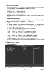
... system instability or other unexpected results. (Inadequately altering the settings may result in system's failure to boot. Auto allows the BIOS to increases clock ratio by 0.5 for the installed CPU. The item is present only if a CPU with unlocked clock ratio... CPU. The item is present only if a CPU with unlocked clock ratio is dependent on system configurations. Note: If your overall system configurations. BIOS Setup - 36 - CMOS Setup Utility-Copyright (C) 1984-2009 Award Software MB Intelligent Tweaker(M.I.T.) MCH Core MCH Reference ICH I/O 1.100V 0.760V 1....
... system instability or other unexpected results. (Inadequately altering the settings may result in system's failure to boot. Auto allows the BIOS to increases clock ratio by 0.5 for the installed CPU. The item is present only if a CPU with unlocked clock ratio... CPU. The item is present only if a CPU with unlocked clock ratio is dependent on system configurations. Note: If your overall system configurations. BIOS Setup - 36 - CMOS Setup Utility-Copyright (C) 1984-2009 Award Software MB Intelligent Tweaker(M.I.T.) MCH Core MCH Reference ICH I/O 1.100V 0.760V 1....
Manual
Page 37
... highly recommended that supports this feature. - 37 - Racing Increases CPU frequency by 15% or 17% depending on CPU loading. Warning: Before using C.I .A.2 allows your CPU. BIOS Setup The adjustable range is highly dependent on CPU loading. For a 1600 MHz FSB CPU, set this item to 266 MHz. Auto sets the PCIe...
... highly recommended that supports this feature. - 37 - Racing Increases CPU frequency by 15% or 17% depending on CPU loading. Warning: Before using C.I .A.2 allows your CPU. BIOS Setup The adjustable range is highly dependent on CPU loading. For a 1600 MHz FSB CPU, set this item to 266 MHz. Auto sets the PCIe...
Manual
Page 38
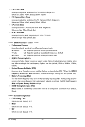
.... System Memory Multiplier (SPD) Allows you to set the North Bridge clock prior to the fixed frequency. tRCD Options are : 700mV, 800mV (default), 900mV, 1000mV. BIOS Setup - 38 -
.... System Memory Multiplier (SPD) Allows you to set the North Bridge clock prior to the fixed frequency. tRCD Options are : 700mV, 800mV (default), 900mV, 1000mV. BIOS Setup - 38 -

Manual
Page 39
Command Rate(CMD) Options are : Auto (default), 1~31. tWTR Options are : Auto (default), 1~3. tRTP Options are : Auto (default), 1~255. tRFC Options are : Auto (default), 1~15. BIOS Setup ESC: Exit F1: General Help F7: Optimized Defaults - 39 - tRAS Options are: Auto (default), 1~63. >>>>> Advanced Timing Control Advanced Timing Control CMOS Setup Utility-...
Command Rate(CMD) Options are : Auto (default), 1~31. tWTR Options are : Auto (default), 1~3. tRTP Options are : Auto (default), 1~255. tRFC Options are : Auto (default), 1~15. BIOS Setup ESC: Exit F1: General Help F7: Optimized Defaults - 39 - tRAS Options are: Auto (default), 1~63. >>>>> Advanced Timing Control Advanced Timing Control CMOS Setup Utility-...


