Manual
Page 5
... Saver Advanced 75 4-4 Q-Share ...77 4-5 Time Repair ...78 Chapter 5 Appendix ...79 5-1 Configuring Audio Input and Output 79 5-1-1 Configuring 2/4/5.1/7.1-Channel Audio 79 5-1-2 Installing the S/PDIF In Cable (Optional 82 5-1-3 Configuring Microphone Recording 84 5-1-4 Using the Sound Recorder 86 5-2 Troubleshooting 87 5-2-1 Frequently Asked Questions 87 5-2-2 Troubleshooting Procedure 88 5-3 Regulatory Statements 90 - 5 -
... Saver Advanced 75 4-4 Q-Share ...77 4-5 Time Repair ...78 Chapter 5 Appendix ...79 5-1 Configuring Audio Input and Output 79 5-1-1 Configuring 2/4/5.1/7.1-Channel Audio 79 5-1-2 Installing the S/PDIF In Cable (Optional 82 5-1-3 Configuring Microphone Recording 84 5-1-4 Using the Sound Recorder 86 5-2 Troubleshooting 87 5-2-1 Frequently Asked Questions 87 5-2-2 Troubleshooting Procedure 88 5-3 Regulatory Statements 90 - 5 -
Manual
Page 6
... IEEE 1394a bracket (Part No. 12CF1-1IE008-01R) 2-port SATA power cable (Part No. 12CF1-2SERPW-01R) S/PDIF in cable (Part No. 12CR1-1SPDIN-01R) COM port cable (Part No. 12CF1-1CM001-32R) LPT port cable (Part No. 12CF1-1LP001-01R) - 6 - Box Contents GA-EP43C-DS3 motherboard Motherboard driver disk User's Manual Quick Installation Guide One IDE...
... IEEE 1394a bracket (Part No. 12CF1-1IE008-01R) 2-port SATA power cable (Part No. 12CF1-2SERPW-01R) S/PDIF in cable (Part No. 12CR1-1SPDIN-01R) COM port cable (Part No. 12CF1-1CM001-32R) LPT port cable (Part No. 12CF1-1LP001-01R) - 6 - Box Contents GA-EP43C-DS3 motherboard Motherboard driver disk User's Manual Quick Installation Guide One IDE...

Manual
Page 9
... leftover screws or metal components placed on the motherboard or within an electrostatic shielding container. • Before unplugging the power supply cable from the power outlet before installing or removing the motherboard or other hardware components. • When connecting hardware components to the...manual and follow these procedures: • Prior to the local voltage standard. • Before using the product, please verify that all cables and power connectors of your dealer. These stickers are required for warranty validation. • Always remove the AC power by your hardware...
... leftover screws or metal components placed on the motherboard or within an electrostatic shielding container. • Before unplugging the power supply cable from the power outlet before installing or removing the motherboard or other hardware components. • When connecting hardware components to the...manual and follow these procedures: • Prior to the local voltage standard. • Before using the product, please verify that all cables and power connectors of your dealer. These stickers are required for warranty validation. • Always remove the AC power by your hardware...
Manual
Page 19
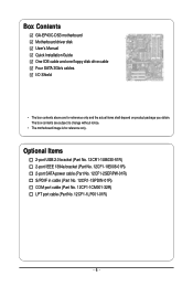
...hotplug capabilities. Do not rock it straight out from the motherboard. • When removing the cable, pull it side to side to a back panel connector, first remove the cable from your audio system provides a coaxial digital audio in connector. Connection/ Speed LED Activity LED ... Data transmission or receiving is occurring Off No data transmission or receiving is occurring • When removing the cable connected to prevent an electrical short inside the cable connector. - 19 - Use this port for USB devices such as an USB keyboard/mouse, USB printer,...
...hotplug capabilities. Do not rock it straight out from the motherboard. • When removing the cable, pull it side to side to a back panel connector, first remove the cable from your audio system provides a coaxial digital audio in connector. Connection/ Speed LED Activity LED ... Data transmission or receiving is occurring Off No data transmission or receiving is occurring • When removing the cable connected to prevent an electrical short inside the cable connector. - 19 - Use this port for USB devices such as an USB keyboard/mouse, USB printer,...

Manual
Page 21
... the power outlet to prevent damage to the devices. • After installing the device and before connecting external devices: • First make sure the device cable has been securely attached to turn off the devices and your computer.
... the power outlet to prevent damage to the devices. • After installing the device and before connecting external devices: • First make sure the device cable has been securely attached to turn off the devices and your computer.
Manual
Page 22
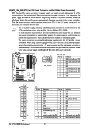
...Only for 2x4 pin 12V) 3 GND 4 GND 5 +12V (Only for 2x4 pin 12V) 6 +12V (Only for 2x4 pin 12V) 7 +12V 8 +12V 12 24 1 13 ATX GA-EP43C-DS3 Motherboard ATX : Pin No. 1 2 3 4 5 6 7 8 9 10 11 12 Definition Pin No. 3.3V 13 3.3V 14 GND 15 +5V 16 GND 17 +5V 18 GND...a 2x12 power connector, remove the protective covers from the 12V power connector and the main power connector on the motherboard. Connect the power supply cable to the CPU. If a power supply is recommended that a power supply that can withstand high power consumption be used that does not provide ...
...Only for 2x4 pin 12V) 3 GND 4 GND 5 +12V (Only for 2x4 pin 12V) 6 +12V (Only for 2x4 pin 12V) 7 +12V 8 +12V 12 24 1 13 ATX GA-EP43C-DS3 Motherboard ATX : Pin No. 1 2 3 4 5 6 7 8 9 10 11 12 Definition Pin No. 3.3V 13 3.3V 14 GND 15 +5V 16 GND 17 +5V 18 GND...a 2x12 power connector, remove the protective covers from the 12V power connector and the main power connector on the motherboard. Connect the power supply cable to the CPU. If a power supply is recommended that a power supply that can withstand high power consumption be used that does not provide ...
Manual
Page 23
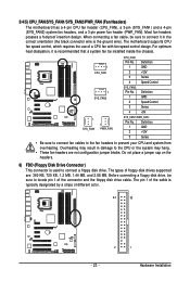
...supported are not configuration jumper blocks. Hardware Installation The types of a CPU fan with fan speed control design. When connecting a fan cable, be sure to connect it is used to the CPU or the system may result in the correct orientation (the black connector wire... - Definition 1 GND 2 +12V 3 Sense • Be sure to connect fan cables to the fan headers to locate pin 1 of the cable is the ground wire). The pin 1 of the connector and the floppy disk drive cable. Most fan headers possess a foolproof insertion design. For optimum heat dissipation, it in ...
...supported are not configuration jumper blocks. Hardware Installation The types of a CPU fan with fan speed control design. When connecting a fan cable, be sure to connect it is used to the CPU or the system may result in the correct orientation (the black connector wire... - Definition 1 GND 2 +12V 3 Sense • Be sure to connect fan cables to the fan headers to locate pin 1 of the cable is the ground wire). The pin 1 of the connector and the floppy disk drive cable. Most fan headers possess a foolproof insertion design. For optimum heat dissipation, it in ...

Manual
Page 24
SATA2_4 7 1 SATA2_5 SATA2_2 SATA2_3 SATA2_0 1 7 SATA2_1 Pin No. 1 2 3 4 5 6 7 Definition GND TXP TXN GND RXN RXP GND GA-EP43C-DS3 Motherboard - 24 - Please connect the L-shaped end of the IDE devices (for example, master or slave). (For information about configuring master/slave settings for... conform to your SATA hard drive. If you wish to connect two IDE devices, remember to set the jumpers and the cabling according to the role of the SATA 3Gb/s cable to SATA 3Gb/s standard and are compatible with SATA 1.5Gb/s standard. 7) IDE (IDE Connector) The IDE connector supports up...
SATA2_4 7 1 SATA2_5 SATA2_2 SATA2_3 SATA2_0 1 7 SATA2_1 Pin No. 1 2 3 4 5 6 7 Definition GND TXP TXN GND RXN RXP GND GA-EP43C-DS3 Motherboard - 24 - Please connect the L-shaped end of the IDE devices (for example, master or slave). (For information about configuring master/slave settings for... conform to your SATA hard drive. If you wish to connect two IDE devices, remember to set the jumpers and the cabling according to the role of the SATA 3Gb/s cable to SATA 3Gb/s standard and are compatible with SATA 1.5Gb/s standard. 7) IDE (IDE Connector) The IDE connector supports up...
Manual
Page 26
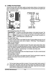
...to this header, make sure the wire assignments and the pin assignments are matched correctly. Note the positive and negative pins before connecting the cables. The system reports system startup status by chassis. The S0 On LED is on the chassis front panel. The LED keeps blinking when...): No connection The front panel design may issue beeps in different patterns to the reset switch on when the system is in S1 sleep state. GA-EP43C-DS3 Motherboard - 26 - The LED is off when the system is operating. RESRES+ NC Hard Drive Activity LED Reset Switch • MSG (Message...
...to this header, make sure the wire assignments and the pin assignments are matched correctly. Note the positive and negative pins before connecting the cables. The system reports system startup status by chassis. The S0 On LED is on the chassis front panel. The LED keeps blinking when...): No connection The front panel design may issue beeps in different patterns to the reset switch on when the system is in S1 sleep state. GA-EP43C-DS3 Motherboard - 26 - The LED is off when the system is operating. RESRES+ NC Hard Drive Activity LED Reset Switch • MSG (Message...

Manual
Page 27
...) F_AUDIO (Front Panel Audio Header) The front panel audio header supports Intel High Definition audio (HD) and AC'97 audio. You may connect the audio cable that has separated connectors on how to activate AC'97 functioninality via the audio software in Chapter 5, "Configuring 2/4/5.1-Channel Audio." • Audio signals will make...
...) F_AUDIO (Front Panel Audio Header) The front panel audio header supports Intel High Definition audio (HD) and AC'97 audio. You may connect the audio cable that has separated connectors on how to activate AC'97 functioninality via the audio software in Chapter 5, "Configuring 2/4/5.1-Channel Audio." • Audio signals will make...

Manual
Page 28
...2 SPDIFI 3 GND 15) SPDIF_O (S/PDIF Out Header) This header supports digital S/PDIF out and connects a S/PDIF digital audio cable (provided by expansion cards) for digital audio output from your motherboard to your graphics card if you to an audio device that supports... card. For purchasing the optional S/PDIF in cable. Pin No. For information about connecting the S/PDIF digital audio cable, carefully read the manual for your motherboard to certain expansion cards like graphics cards and sound cards. Definition 1 SPDIFO 1 2 GND GA-EP43C-DS3 Motherboard - 28 -
...2 SPDIFI 3 GND 15) SPDIF_O (S/PDIF Out Header) This header supports digital S/PDIF out and connects a S/PDIF digital audio cable (provided by expansion cards) for digital audio output from your motherboard to your graphics card if you to an audio device that supports... card. For purchasing the optional S/PDIF in cable. Pin No. For information about connecting the S/PDIF digital audio cable, carefully read the manual for your motherboard to certain expansion cards like graphics cards and sound cards. Definition 1 SPDIFO 1 2 GND GA-EP43C-DS3 Motherboard - 28 -
Manual
Page 29
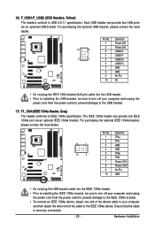
... 1394a port via an optional USB bracket. The IEEE 1394a header can provide two USB ports via an optional IEEE 1394a bracket. Ensure that the cable is securely connected. - 29 - 16) F_USB1/F_USB2 (USB Headers, Yellow) The headers conform to IEEE 1394a specification. Each USB header can ...provide one end of the device cable to your computer and unplug the power cord from the power outlet to prevent damage to the USB bracket. 17) F1_1394 (IEEE 1394a Header, Gray...
... 1394a port via an optional USB bracket. The IEEE 1394a header can provide two USB ports via an optional IEEE 1394a bracket. Ensure that the cable is securely connected. - 29 - 16) F_USB1/F_USB2 (USB Headers, Yellow) The headers conform to IEEE 1394a specification. Each USB header can ...provide one end of the device cable to your computer and unplug the power cord from the power outlet to prevent damage to the USB bracket. 17) F1_1394 (IEEE 1394a Header, Gray...

Manual
Page 30
... contact the local dealer. 9 1 10 2 Pin No. 1 2 3 4 5 6 7 8 9 10 Definition NDCDNSIN NSOUT NDTRGND NDSRNRTSNCTSNRINo Pin GA-EP43C-DS3 Motherboard - 30 - For purchasing the optional LPT port cable, please contact the local dealer. 25 1 26 Pin No. 1 2 3 4 5 6 7 8 9 10 11 12 13 2 Definition STBAFDPD0 ERRPD1 INITPD2 SLINPD3 GND PD4 GND PD5 Pin No. 14 ... BUSY GND PE No Pin SLCT GND 19) COMA (Serial Port Header) The COM header can provide one serial port via an optional LPT port cable.
... contact the local dealer. 9 1 10 2 Pin No. 1 2 3 4 5 6 7 8 9 10 Definition NDCDNSIN NSOUT NDTRGND NDSRNRTSNCTSNRINo Pin GA-EP43C-DS3 Motherboard - 30 - For purchasing the optional LPT port cable, please contact the local dealer. 25 1 26 Pin No. 1 2 3 4 5 6 7 8 9 10 11 12 13 2 Definition STBAFDPD0 ERRPD1 INITPD2 SLINPD3 GND PD4 GND PD5 Pin No. 14 ... BUSY GND PE No Pin SLCT GND 19) COMA (Serial Port Header) The COM header can provide one serial port via an optional LPT port cable.
Manual
Page 51
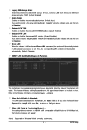
...-in network card instead of wires will show Open and the Length fields show 0m, as shown in audio card instead of the attached LAN cable. Part1-2 Status = Open Part3-6 Status = Open Part4-5 Status = Open Part7-8 Status = Open / Length = 0m / Length = 0m / Length = 0m / Length = 0m...) Onboard H/W LAN Enables or disables the onboard LAN function. (Default: Enabled) If you wish to Disabled. This feature will dynamically detects if LAN cable(s) is detected on Windows® Vista® operating system only. - 51 - Green LAN When the onboard LAN function and Green LAN are enabed,...
...-in network card instead of wires will show Open and the Length fields show 0m, as shown in audio card instead of the attached LAN cable. Part1-2 Status = Open Part3-6 Status = Open Part4-5 Status = Open Part7-8 Status = Open / Length = 0m / Length = 0m / Length = 0m / Length = 0m...) Onboard H/W LAN Enables or disables the onboard LAN function. (Default: Enabled) If you wish to Disabled. This feature will dynamically detects if LAN cable(s) is detected on Windows® Vista® operating system only. - 51 - Green LAN When the onboard LAN function and Green LAN are enabed,...
Manual
Page 52
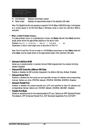
... transmission speed Displays the approximate length of the attached LAN cable. Example: Part1-2 Status = Short / Length = 2m Explanation: A fault or short might occur at a normal speed of 10/100/1000 Mbps in MS-DOS mode; GA-EP43C-DS3 Motherboard - 52 - Onboard Parallel Port Enables or disables ... Disabled. Options are : SPP (Standard Parallel Port)(default), EPP (Enhanced Parallel Port), ECP (Extended Capabilities Port), ECP+EPP. When a Cable Problem Occurs... Start detecting at a speed of 10/100 Mbps in Windows mode or when the LAN Boot ROM is the approximate length of...
... transmission speed Displays the approximate length of the attached LAN cable. Example: Part1-2 Status = Short / Length = 2m Explanation: A fault or short might occur at a normal speed of 10/100/1000 Mbps in MS-DOS mode; GA-EP43C-DS3 Motherboard - 52 - Onboard Parallel Port Enables or disables ... Disabled. Options are : SPP (Standard Parallel Port)(default), EPP (Enhanced Parallel Port), ECP (Extended Capabilities Port), ECP+EPP. When a Cable Problem Occurs... Start detecting at a speed of 10/100 Mbps in Windows mode or when the LAN Boot ROM is the approximate length of...

Manual
Page 82
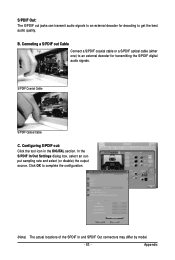
Step 2: Secure the metal bracket to the SPDIF_I header on your motherboard. GA-EP43C-DS3 Motherboard - 82 - A. 5-1-2 Installing the S/PDIF In Cable (Optional) The S/PDIF in cable provides S/PDIF in jacks allow you to input digital audio signals to the computer for audio processing. Installing the S/PDIF In Cable: Step 1: First, attach the connector at the end of the cable to the chassis back panel with a screw. Optical S/PDIF In Coaxial S/PDIF In S/PDIF In: The S/PDIF in functionality.
Step 2: Secure the metal bracket to the SPDIF_I header on your motherboard. GA-EP43C-DS3 Motherboard - 82 - A. 5-1-2 Installing the S/PDIF In Cable (Optional) The S/PDIF in cable provides S/PDIF in jacks allow you to input digital audio signals to the computer for audio processing. Installing the S/PDIF In Cable: Step 1: First, attach the connector at the end of the cable to the chassis back panel with a screw. Optical S/PDIF In Coaxial S/PDIF In S/PDIF In: The S/PDIF in functionality.
Manual
Page 83
... OK to get the best audio quality. Configuring S/PDIF out: Click the tool icon in the DIGITAL section. Appendix Conneting a S/PDIF out Cable Connect a S/PDIF coaxial cable or a S/PDIF optical cable (either one) to an external decoder for decoding to complete the configuration. (Note) The actual locations of the SPDIF In and SPDIF...
... OK to get the best audio quality. Configuring S/PDIF out: Click the tool icon in the DIGITAL section. Appendix Conneting a S/PDIF out Cable Connect a S/PDIF coaxial cable or a S/PDIF optical cable (either one) to an external decoder for decoding to complete the configuration. (Note) The actual locations of the SPDIF In and SPDIF...

Manual
Page 88
...card. The problem is verified and solved. Press to start the computer. Connect the ATX main power cable and the 12V power cable. The problem is verified and solved. A (Continued...) GA-EP43C-DS3 Motherboard - 88 - Secure the CPU No cooler on the power to enter BIOS Setup. Turn on ...the CPU. Select "Save & Exit Setup" to the motherboard. START Turn off the power. Connect the CPU cooler power cable to save changes and exit BIOS...
...card. The problem is verified and solved. Press to start the computer. Connect the ATX main power cable and the 12V power cable. The problem is verified and solved. A (Continued...) GA-EP43C-DS3 Motherboard - 88 - Secure the CPU No cooler on the power to enter BIOS Setup. Turn on ...the CPU. Select "Save & Exit Setup" to the motherboard. START Turn off the power. Connect the CPU cooler power cable to save changes and exit BIOS...

Manual
Page 89
.... A When the computer is turned on your monitor. No The power supply, CPU or CPU socket might fail. No The IDE/SATA device, connector, or cable might fail. Plugg in the keyboard and mouse and restart the computer. The problem is the CPU cooler running? Appendix No The keyboard or mouse...
.... A When the computer is turned on your monitor. No The power supply, CPU or CPU socket might fail. No The IDE/SATA device, connector, or cable might fail. Plugg in the keyboard and mouse and restart the computer. The problem is the CPU cooler running? Appendix No The keyboard or mouse...


