Manual
Page 8
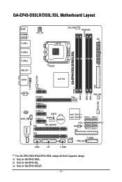
Only for GA-EP43-DS3L. GA-EP43-DS3LR/DS3L/S3L Motherboard Layout KB_MS R_SPDIF COAXIAL R_USB_1 R_USB_2 R_USB_3 ATX_12V CPU_FAN PHASE LED ATX LGA775 DDR2_1 GA-EP43-DS3LR/DS3L/S3L DDR2_2 DDR2_3 DDR2_4 FDD SYS_FAN2 USB_LAN AUDIO Intel® P43 F_AUDIO SYS_FAN1 RTL8111C PCIEX1_1 PCIEX16 PCIEX1_2 PWR_FAN CODEC SPDIF_O ...ICH10 Intel® ICH10R SATA2_3 SATA2_0 SATA2_4 SATA2_ 1 JMicron 368 IDE SATA2_5 SATA2_2 F_USB1 F_PANEL PWR_LED COMA LPT F_USB2 "*" The GA-EP43-DS3LR/GA-EP43-DS3L adopts All-Solid Capacitor design. Only for GA-EP43-S3L. Only for GA-EP43-DS3LR. - 8 -
Only for GA-EP43-DS3L. GA-EP43-DS3LR/DS3L/S3L Motherboard Layout KB_MS R_SPDIF COAXIAL R_USB_1 R_USB_2 R_USB_3 ATX_12V CPU_FAN PHASE LED ATX LGA775 DDR2_1 GA-EP43-DS3LR/DS3L/S3L DDR2_2 DDR2_3 DDR2_4 FDD SYS_FAN2 USB_LAN AUDIO Intel® P43 F_AUDIO SYS_FAN1 RTL8111C PCIEX1_1 PCIEX16 PCIEX1_2 PWR_FAN CODEC SPDIF_O ...ICH10 Intel® ICH10R SATA2_3 SATA2_0 SATA2_4 SATA2_ 1 JMicron 368 IDE SATA2_5 SATA2_2 F_USB1 F_PANEL PWR_LED COMA LPT F_USB2 "*" The GA-EP43-DS3LR/GA-EP43-DS3L adopts All-Solid Capacitor design. Only for GA-EP43-S3L. Only for GA-EP43-DS3LR. - 8 -
Manual
Page 13
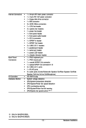
... 1 x CD In connector Š 1 x S/PDIF In header Š 1 x S/PDIF Out header Š 2 x USB 2.0/1.1 headers Š 1 x parallel port header Š 1 x serial port header Š 1 x power LED header Š 1 x chassis intrusion header Back Panel Š 1 x PS/2 keyboard port Connectors Š 1 x PS/2 mouse port Š 1 x coaxial S/PDIF Out connector Š 1 x optical S/PDIF Out...Power fan speed detection Š CPU overheating warning Š CPU/System/Power fan fail warning Š CPU/System fan speed control (Note 2) Only for GA-EP43-DS3LR. - 13 - Hardware Installation
... 1 x CD In connector Š 1 x S/PDIF In header Š 1 x S/PDIF Out header Š 2 x USB 2.0/1.1 headers Š 1 x parallel port header Š 1 x serial port header Š 1 x power LED header Š 1 x chassis intrusion header Back Panel Š 1 x PS/2 keyboard port Connectors Š 1 x PS/2 mouse port Š 1 x coaxial S/PDIF Out connector Š 1 x optical S/PDIF Out...Power fan speed detection Š CPU overheating warning Š CPU/System/Power fan fail warning Š CPU/System fan speed control (Note 2) Only for GA-EP43-DS3LR. - 13 - Hardware Installation
Manual
Page 21
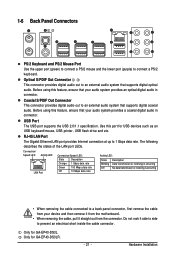
...Only for GA-EP43-DS3LR. - 21 - 1-6 Back Panel Connectors PS/2 Keyboard and PS/2 Mouse Port Use the upper port (green) to connect a PS/2 mouse and the lower port (purple) to 1 Gbps data rate. Connection/ Speed LED Activity LED LAN Port Connection/Speed LED: State...back panel connector, first remove the cable from the connector. The following describes the states of the LAN port LEDs. Do not rock it side to side to an external audio system that your device and then remove it from.... USB Port The USB port supports the USB 2.0/1.1 specification. Only for GA-EP43-DS3L.
...Only for GA-EP43-DS3LR. - 21 - 1-6 Back Panel Connectors PS/2 Keyboard and PS/2 Mouse Port Use the upper port (green) to connect a PS/2 mouse and the lower port (purple) to 1 Gbps data rate. Connection/ Speed LED Activity LED LAN Port Connection/Speed LED: State...back panel connector, first remove the cable from the connector. The following describes the states of the LAN port LEDs. Do not rock it side to side to an external audio system that your device and then remove it from.... USB Port The USB port supports the USB 2.0/1.1 specification. Only for GA-EP43-DS3L.
Manual
Page 23
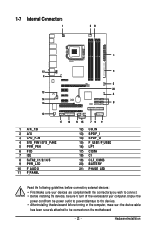
... 10) F_AUDIO 11) F_PANEL 12) CD_IN 13) SPDIF_I 14) SPDIF_O 15) F_USB1/F_USB2 16) LPT 17) COMA 18) CI 19) CLR_CMOS 20) BATTERY 21) PHASE LED Read the following guidelines before turning on the motherboard. - 23 - Unplug the power cord from the power outlet to prevent damage to the devices. •...
... 10) F_AUDIO 11) F_PANEL 12) CD_IN 13) SPDIF_I 14) SPDIF_O 15) F_USB1/F_USB2 16) LPT 17) COMA 18) CI 19) CLR_CMOS 20) BATTERY 21) PHASE LED Read the following guidelines before turning on the motherboard. - 23 - Unplug the power cord from the power outlet to prevent damage to the devices. •...

Manual
Page 27
...8226; A RAID 5 configuration requires at least three hard drives. (The total number of hard drives must be an even number. 9) PWR_LED (System Power LED Header) This header can be an even number.) • A RAID 10 configuration requires at least two hard drives. Definition 1 GND 2 TXP 7 ...RXP SATA2_5 SATA2_2 7 GND 7 17 1 Please connect the L-shaped end of the SATA 3Gb/s cable to Chapter 5, "Configuring SATA Hard Drive(s)," for GA-EP43-DS3LR. - 27 - System Status LED S0 On S1 Blinking S3/S4/S5 Off Only for instructions on when the system is in S1 sleep state.
...8226; A RAID 5 configuration requires at least three hard drives. (The total number of hard drives must be an even number. 9) PWR_LED (System Power LED Header) This header can be an even number.) • A RAID 10 configuration requires at least two hard drives. Definition 1 GND 2 TXP 7 ...RXP SATA2_5 SATA2_2 7 GND 7 17 1 Please connect the L-shaped end of the SATA 3Gb/s cable to Chapter 5, "Configuring SATA Hard Drive(s)," for GA-EP43-DS3LR. - 27 - System Status LED S0 On S1 Blinking S3/S4/S5 Off Only for instructions on when the system is in S1 sleep state.
Manual
Page 29
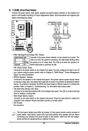
... power switch (refer to Chapter 2, "BIOS Setup," "Power Management Setup," for information about beep codes. • HD (Hard Drive Activity LED, Blue) Connects to the speaker on the chassis front panel. Note the positive and negative pins before connecting the cables. A front panel module... mainly consists of power switch, reset switch, power LED, hard drive activity LED, speaker and etc. 11) F_PANEL (Front Panel Header) Connect the power switch, reset switch, speaker and system status indicator on...
... power switch (refer to Chapter 2, "BIOS Setup," "Power Management Setup," for information about beep codes. • HD (Hard Drive Activity LED, Blue) Connects to the speaker on the chassis front panel. Note the positive and negative pins before connecting the cables. A front panel module... mainly consists of power switch, reset switch, power LED, hard drive activity LED, speaker and etc. 11) F_PANEL (Front Panel Header) Connect the power switch, reset switch, speaker and system status indicator on...

Manual
Page 34
...Contact the place of purchase or local dealer if you are not able to replace the battery by removing the battery: 1. Replace the battery. 4. GA-EP43-DS3LR/DS3L/S3L Motherboard - 34 - Danger of explosion if the battery is turned off your computer and unplug the power cord before replacing the battery. • ...the battery voltage drops to touch the positive and negative terminals of the battery holder, making them short for more the number of lighted LEDs indicates the CPU loading. You may be handled in the power cord and restart your computer and unplug the power cord. 2.
...Contact the place of purchase or local dealer if you are not able to replace the battery by removing the battery: 1. Replace the battery. 4. GA-EP43-DS3LR/DS3L/S3L Motherboard - 34 - Danger of explosion if the battery is turned off your computer and unplug the power cord before replacing the battery. • ...the battery voltage drops to touch the positive and negative terminals of the battery holder, making them short for more the number of lighted LEDs indicates the CPU loading. You may be handled in the power cord and restart your computer and unplug the power cord. 2.

Manual
Page 75
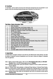
... that delivers unparalleled power savings with a click of time. The Dynamic Energy Saver Advanced Interface A. Meter Mode In Meter Mode, GIGABYTE Dynamic Energy Saver Advanced shows how much power they have saved in taskbar) 16 INFO/Help 17 Live Utility Update (Check for the... to run in a set period of the button. Button Information Table Button Description 1 Dynamic Energy Saver On/Off Switch (Default: Off) 2 Motherboard Phase LED On/Off Switch (Default: On) 3 Dynamic CPU Frequency Function On/Off Switch (Default: Off) (Note 2) 4 CPU Throttling Display 5 3-Level CPU Voltage...
... that delivers unparalleled power savings with a click of time. The Dynamic Energy Saver Advanced Interface A. Meter Mode In Meter Mode, GIGABYTE Dynamic Energy Saver Advanced shows how much power they have saved in taskbar) 16 INFO/Help 17 Live Utility Update (Check for the... to run in a set period of the button. Button Information Table Button Description 1 Dynamic Energy Saver On/Off Switch (Default: Off) 2 Motherboard Phase LED On/Off Switch (Default: On) 3 Dynamic CPU Frequency Function On/Off Switch (Default: Off) (Note 2) 4 CPU Throttling Display 5 3-Level CPU Voltage...
Manual
Page 76
GA-EP43-DS3LR/DS3L/S3L Motherboard - 76 - Button Information Table Button Description 1 Dynamic Energy Saver On/Off Switch (Default: Off) 2 Motherboard Phase LED On/Off Switch (Default: On) 3 Dynamic CPU Frequency Function On/Off Switch (Default: Off) 4 CPU Throttling Display 5 3-Level CPU Voltage Switch (Default:1) (Note 3) 6 CPU Voltage ...
GA-EP43-DS3LR/DS3L/S3L Motherboard - 76 - Button Information Table Button Description 1 Dynamic Energy Saver On/Off Switch (Default: Off) 2 Motherboard Phase LED On/Off Switch (Default: On) 3 Dynamic CPU Frequency Function On/Off Switch (Default: Off) 4 CPU Throttling Display 5 3-Level CPU Voltage Switch (Default:1) (Note 3) 6 CPU Voltage ...


