Manual
Page 1
GA-EP43-DS3LR/ GA-EP43-DS3L/ GA-EP43-S3L LGA775 socket motherboard for Intel® CoreTM processor family/ Intel® Pentium® processor family/Intel® Celeron® processor family User's Manual Rev. 1006 12ME-EP43DS3L-1006R
GA-EP43-DS3LR/ GA-EP43-DS3L/ GA-EP43-S3L LGA775 socket motherboard for Intel® CoreTM processor family/ Intel® Pentium® processor family/Intel® Celeron® processor family User's Manual Rev. 1006 12ME-EP43DS3L-1006R
Manual
Page 2
Motherboard GA-EP43-DS3L/GA-EP43-S3L May 23, 2008 Motherboard GA-EP43-DS3L/ GA-EP43-S3L May 23, 2008
Motherboard GA-EP43-DS3L/GA-EP43-S3L May 23, 2008 Motherboard GA-EP43-DS3L/ GA-EP43-S3L May 23, 2008
Manual
Page 3
Motherboard GA-EP43-DS3LR Oct. 9, 2008 Motherboard GA-EP43-DS3LR Oct. 9, 2008
Motherboard GA-EP43-DS3LR Oct. 9, 2008 Motherboard GA-EP43-DS3LR Oct. 9, 2008
Manual
Page 4
... without prior notice. No part of this manual may be made by any form or by GIGABYTE without GIGABYTE's prior written permission. For example, "REV: 1.0" means the revision of the motherboard is the property of this : "REV: X.X." Disclaimer Information in this manual is protected by... copyright laws and is 1.0. The trademarks mentioned in this manual are legally registered to use of GIGABYTE. Check your motherboard looks like this product, GIGABYTE provides the following types of documentations: „ For quick set-up of the product, read the Quick...
... without prior notice. No part of this manual may be made by any form or by GIGABYTE without GIGABYTE's prior written permission. For example, "REV: 1.0" means the revision of the motherboard is the property of this : "REV: X.X." Disclaimer Information in this manual is protected by... copyright laws and is 1.0. The trademarks mentioned in this manual are legally registered to use of GIGABYTE. Check your motherboard looks like this product, GIGABYTE provides the following types of documentations: „ For quick set-up of the product, read the Quick...
Manual
Page 5
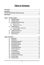
Table of Contents Box Contents ...7 OptionalItems...7 GA-EP43-DS3LR/DS3L/S3L Motherboard Layout 8 Block Diagram...9 Chapter 1 Hardware Installation 11 1-1 Installation Precautions 11 1-2 Product Specifications 12 1-3 Installing the CPU and CPU Cooler 15 1-3-1 Installing the CPU 15 1-3-2 Installing ...
Table of Contents Box Contents ...7 OptionalItems...7 GA-EP43-DS3LR/DS3L/S3L Motherboard Layout 8 Block Diagram...9 Chapter 1 Hardware Installation 11 1-1 Installation Precautions 11 1-2 Product Specifications 12 1-3 Installing the CPU and CPU Cooler 15 1-3-1 Installing the CPU 15 1-3-2 Installing ...
Manual
Page 7
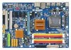
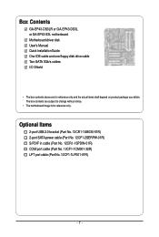
Box Contents GA-EP43-DS3LR or GA-EP43-DS3L or GA-EP43-S3L motherboard Motherboard driver disk User's Manual Quick Installation Guide One IDE cable and one floppy disk drive cable Two SATA 3Gb/s cables I/O Shield • The box contents above are subject to change without notice. • The motherboard image is for reference only and the actual items shall depend...
Box Contents GA-EP43-DS3LR or GA-EP43-DS3L or GA-EP43-S3L motherboard Motherboard driver disk User's Manual Quick Installation Guide One IDE cable and one floppy disk drive cable Two SATA 3Gb/s cables I/O Shield • The box contents above are subject to change without notice. • The motherboard image is for reference only and the actual items shall depend...
Manual
Page 8
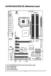
Only for GA-EP43-DS3L. Only for GA-EP43-DS3LR. - 8 - GA-EP43-DS3LR/DS3L/S3L Motherboard Layout KB_MS R_SPDIF COAXIAL R_USB_1 R_USB_2 R_USB_3 ATX_12V CPU_FAN PHASE LED ATX LGA775 DDR2_1 GA-EP43-DS3LR/DS3L/S3L DDR2_2 DDR2_3 DDR2_4 FDD SYS_FAN2 USB_LAN AUDIO Intel® P43 F_AUDIO SYS_FAN1 RTL8111C PCIEX1_1 PCIEX16 PCIEX1_2 PWR_FAN CODEC SPDIF_O ...ICH10 Intel® ICH10R SATA2_3 SATA2_0 SATA2_4 SATA2_ 1 JMicron 368 IDE SATA2_5 SATA2_2 F_USB1 F_PANEL PWR_LED COMA LPT F_USB2 "*" The GA-EP43-DS3LR/GA-EP43-DS3L adopts All-Solid Capacitor design. Only for GA-EP43-S3L.
Only for GA-EP43-DS3L. Only for GA-EP43-DS3LR. - 8 - GA-EP43-DS3LR/DS3L/S3L Motherboard Layout KB_MS R_SPDIF COAXIAL R_USB_1 R_USB_2 R_USB_3 ATX_12V CPU_FAN PHASE LED ATX LGA775 DDR2_1 GA-EP43-DS3LR/DS3L/S3L DDR2_2 DDR2_3 DDR2_4 FDD SYS_FAN2 USB_LAN AUDIO Intel® P43 F_AUDIO SYS_FAN1 RTL8111C PCIEX1_1 PCIEX16 PCIEX1_2 PWR_FAN CODEC SPDIF_O ...ICH10 Intel® ICH10R SATA2_3 SATA2_0 SATA2_4 SATA2_ 1 JMicron 368 IDE SATA2_5 SATA2_2 F_USB1 F_PANEL PWR_LED COMA LPT F_USB2 "*" The GA-EP43-DS3LR/GA-EP43-DS3L adopts All-Solid Capacitor design. Only for GA-EP43-S3L.

Manual
Page 11
...within an electrostatic shielding container. • Before unplugging the power supply cable from the power outlet before installing or removing the motherboard or other hardware components. • When connecting hardware components to the internal connectors on the computer power during the installation ...for warranty validation. • Always remove the AC power by your hardware components are connected. • To prevent damage to the motherboard, do not allow screws to wear an electrostatic discharge (ESD) wrist strap when handling electronic components such as a result of your ...
...within an electrostatic shielding container. • Before unplugging the power supply cable from the power outlet before installing or removing the motherboard or other hardware components. • When connecting hardware components to the internal connectors on the computer power during the installation ...for warranty validation. • Always remove the AC power by your hardware components are connected. • To prevent damage to the motherboard, do not allow screws to wear an electrostatic discharge (ESD) wrist strap when handling electronic components such as a result of your ...
Manual
Page 12
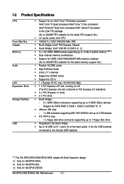
... 1) Š Dual channel memory architecture Š Support for DDR2 1200/1066/800/667 MHz memory modules (Go to GIGABYTE's website for the latest memory support list.) Š Realtek ALC888 codec Š High Definition Audio Š 2/4/5.1/7.1-channel ...SATA 3Gb/s connectors supporting up to the internal USB headers) "*" The GA-EP43-DS3LR/GA-EP43-DS3L adopts All-Solid Capacitor design. Only for GA-EP43-DS3LR. Only for GA-EP43-DS3L. GA-EP43-DS3LR/DS3L/S3L Motherboard - 12 - Only for GA-EP43-S3L. 1-2 Product Specifications CPU Front Side Bus Chipset Memory Audio LAN Expansion ...
... 1) Š Dual channel memory architecture Š Support for DDR2 1200/1066/800/667 MHz memory modules (Go to GIGABYTE's website for the latest memory support list.) Š Realtek ALC888 codec Š High Definition Audio Š 2/4/5.1/7.1-channel ...SATA 3Gb/s connectors supporting up to the internal USB headers) "*" The GA-EP43-DS3LR/GA-EP43-DS3L adopts All-Solid Capacitor design. Only for GA-EP43-DS3LR. Only for GA-EP43-DS3L. GA-EP43-DS3LR/DS3L/S3L Motherboard - 12 - Only for GA-EP43-S3L. 1-2 Product Specifications CPU Front Side Bus Chipset Memory Audio LAN Expansion ...

Manual
Page 14
GA-EP43-DS3LR/DS3L/S3L Motherboard - 14 - BIOS Unique Features Bundled Software Operating System Form Factor Š 2 x 8 Mbit flash Š Use of licensed AWARD BIOS Š Support for DualBIOSTM Š PnP 1.... CPU/System fan speed control function is supported will depend on the CPU/ System cooler you install. (Note 3) Available functions in EasyTune may differ by motherboard model.
GA-EP43-DS3LR/DS3L/S3L Motherboard - 14 - BIOS Unique Features Bundled Software Operating System Form Factor Š 2 x 8 Mbit flash Š Use of licensed AWARD BIOS Š Support for DualBIOSTM Š PnP 1.... CPU/System fan speed control function is supported will depend on the CPU/ System cooler you install. (Note 3) Available functions in EasyTune may differ by motherboard model.
Manual
Page 15
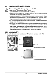
Hardware Installation mended that the motherboard supports the CPU. (Go to GIGABYTE's website for the peripherals. The CPU cannot be set the frequency beyond hardware specifications since it does not meet the standard requirements for the latest ... CPU Alignment Key Pin One Corner of thermal grease on the computer if the CPU cooler is not recom- Locate the alignment keys on the motherboard CPU socket and the notches on the CPU - 15 - It is not installed, otherwise overheating and damage of the CPU may locate the notches on...
Hardware Installation mended that the motherboard supports the CPU. (Go to GIGABYTE's website for the peripherals. The CPU cannot be set the frequency beyond hardware specifications since it does not meet the standard requirements for the latest ... CPU Alignment Key Pin One Corner of thermal grease on the computer if the CPU cooler is not recom- Locate the alignment keys on the motherboard CPU socket and the notches on the CPU - 15 - It is not installed, otherwise overheating and damage of the CPU may locate the notches on...

Manual
Page 16
... NOT touch socket contacts.) Step 3: Remove the protective socket cover from the power outlet to prevent damage to correctly install the CPU into the motherboard CPU socket. Align the CPU pin one marking (triangle) with the pin one corner of the CPU socket (or you may align the CPU...the CPU is not installed.) Step 4: Hold the CPU with the socket alignment keys) and gently insert the CPU into its locked position. B. GA-EP43-DS3LR/DS3L/S3L Motherboard - 16 - Follow the steps below to the CPU. Before installing the CPU, make sure to turn off the computer and unplug the power cord...
... NOT touch socket contacts.) Step 3: Remove the protective socket cover from the power outlet to prevent damage to correctly install the CPU into the motherboard CPU socket. Align the CPU pin one marking (triangle) with the pin one corner of the CPU socket (or you may align the CPU...the CPU is not installed.) Step 4: Hold the CPU with the socket alignment keys) and gently insert the CPU into its locked position. B. GA-EP43-DS3LR/DS3L/S3L Motherboard - 16 - Follow the steps below to the CPU. Before installing the CPU, make sure to turn off the computer and unplug the power cord...
Manual
Page 17
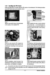
.... If the push pin is to the CPU. Step 6: Finally, attach the power connector of arrow is to the CPU fan header (CPU_FAN) on the motherboard. Use extreme care when removing the CPU cooler because the thermal grease/tape between the CPU cooler and CPU may damage the CPU. - 17 - Step... 4: You should hear a "click" when pushing down on the surface of the motherboard. Hardware Installation Direction of the Arrow Sign on the Male Push Pin Male Push Pin The Top of Female Push Pin Female Push Pin Step...
.... If the push pin is to the CPU. Step 6: Finally, attach the power connector of arrow is to the CPU fan header (CPU_FAN) on the motherboard. Use extreme care when removing the CPU cooler because the thermal grease/tape between the CPU cooler and CPU may damage the CPU. - 17 - Step... 4: You should hear a "click" when pushing down on the surface of the motherboard. Hardware Installation Direction of the Arrow Sign on the Male Push Pin Male Push Pin The Top of Female Push Pin Female Push Pin Step...

Manual
Page 18
... cord from the power outlet before installing the memory to GIGABYTE's website for optimum performance. DS/SS - - If you begin to insert the memory, switch the direction. 1-4-1 Dual Channel Memory Configuration This motherboard provides four DDR2 memory sockets and supports Dual Channel Technology....Channel mode with two or four memory modules, it is operating in only one DDR2 memory module is recommended that the motherboard supports the memory. GA-EP43-DS3LR/DS3L/S3L Motherboard - 18 - It is installed. 2. A memory module can be installed in Flex Memory Mode will double the ...
... cord from the power outlet before installing the memory to GIGABYTE's website for optimum performance. DS/SS - - If you begin to insert the memory, switch the direction. 1-4-1 Dual Channel Memory Configuration This motherboard provides four DDR2 memory sockets and supports Dual Channel Technology....Channel mode with two or four memory modules, it is operating in only one DDR2 memory module is recommended that the motherboard supports the memory. GA-EP43-DS3LR/DS3L/S3L Motherboard - 18 - It is installed. 2. A memory module can be installed in Flex Memory Mode will double the ...
Manual
Page 19
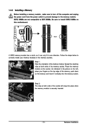
... , make sure to turn off the computer and unplug the power cord from the power outlet to prevent damage to install DDR2 DIMMs on this motherboard. Notch DDR2 DIMM A DDR2 memory module has a notch, so it vertically into place when the memory module is securely inserted. - 19 - As indicated in the...
... , make sure to turn off the computer and unplug the power cord from the power outlet to prevent damage to install DDR2 DIMMs on this motherboard. Notch DDR2 DIMM A DDR2 memory module has a notch, so it vertically into place when the memory module is securely inserted. - 19 - As indicated in the...

Manual
Page 20
...an expansion slot that came with your card. Secure the card's metal bracket to install an expansion card: • Make sure the motherboard supports the expansion card. Install the driver provided with the expansion card in the slot. 3. Example: Installing and Removing a PCI Express ... necessary, go to BIOS Setup to correctly install your expansion card(s). 7. After installing all expansion cards, replace the chassis cover(s). 6. GA-EP43-DS3LR/DS3L/S3L Motherboard - 20 - PCI Express x1 Slot PCI Express x16 Slot PCI Slot Follow the steps below to make any required BIOS changes for ...
...an expansion slot that came with your card. Secure the card's metal bracket to install an expansion card: • Make sure the motherboard supports the expansion card. Install the driver provided with the expansion card in the slot. 3. Example: Installing and Removing a PCI Express ... necessary, go to BIOS Setup to correctly install your expansion card(s). 7. After installing all expansion cards, replace the chassis cover(s). 6. GA-EP43-DS3LR/DS3L/S3L Motherboard - 20 - PCI Express x1 Slot PCI Express x16 Slot PCI Slot Follow the steps below to make any required BIOS changes for ...
Manual
Page 21
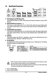
Use this port for GA-EP43-DS3LR. - 21 - The following describes the states of the LAN port LEDs. Only for USB devices such as an USB keyboard/mouse, USB printer, USB ... the motherboard. • When removing the cable, pull it side to side to prevent an electrical short inside the cable connector. USB Port The USB port supports the USB 2.0/1.1 specification. RJ-45 LAN Port The Gigabit Ethernet LAN port provides Internet connection at up to connect a PS/2 keyboard. Only for GA-EP43-DS3L...
Use this port for GA-EP43-DS3LR. - 21 - The following describes the states of the LAN port LEDs. Only for USB devices such as an USB keyboard/mouse, USB printer, USB ... the motherboard. • When removing the cable, pull it side to side to prevent an electrical short inside the cable connector. USB Port The USB port supports the USB 2.0/1.1 specification. RJ-45 LAN Port The Gigabit Ethernet LAN port provides Internet connection at up to connect a PS/2 keyboard. Only for GA-EP43-DS3L...
Manual
Page 22
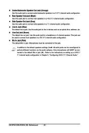
... jack for line in a 4/5.1/7.1-channel audio configuration. Microphones must be reconfigured to connect rear speakers in devices such as an optical drive, walkman, etc. GA-EP43-DS3LR/DS3L/S3L Motherboard - 22 - Center/Subwoofer Speaker Out Jack (Orange) Use this jack. In addition to the default speakers settings, the ~ audio jacks can be connected to...
... jack for line in a 4/5.1/7.1-channel audio configuration. Microphones must be reconfigured to connect rear speakers in devices such as an optical drive, walkman, etc. GA-EP43-DS3LR/DS3L/S3L Motherboard - 22 - Center/Subwoofer Speaker Out Jack (Orange) Use this jack. In addition to the default speakers settings, the ~ audio jacks can be connected to...
Manual
Page 23
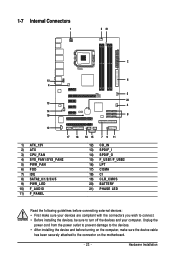
...) SPDIF_O 15) F_USB1/F_USB2 16) LPT 17) COMA 18) CI 19) CLR_CMOS 20) BATTERY 21) PHASE LED Read the following guidelines before turning on the motherboard. - 23 -
...) SPDIF_O 15) F_USB1/F_USB2 16) LPT 17) COMA 18) CI 19) CLR_CMOS 20) BATTERY 21) PHASE LED Read the following guidelines before turning on the motherboard. - 23 -
Manual
Page 24
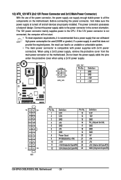
... power supply cable into pins under the protective cover when using a 2x12 power supply, remove the protective cover from the main power connector on the motherboard. The power connector possesses a foolproof design. If a power supply is compatible with power supplies with 2x10 power connectors. When using a 2x10 power ... PS_ON(soft On/Off) GND GND GND -5V +5V +5V +5V (Only for 2x12-pinATX) GND (Only for 2x12-pin ATX) GA-EP43-DS3LR/DS3L/S3L Motherboard - 24 - If the 12V power connector is not connected, the computer will not start. • To meet expansion requirements, it is ...
... power supply cable into pins under the protective cover when using a 2x12 power supply, remove the protective cover from the main power connector on the motherboard. The power connector possesses a foolproof design. If a power supply is compatible with power supplies with 2x10 power connectors. When using a 2x10 power ... PS_ON(soft On/Off) GND GND GND -5V +5V +5V +5V (Only for 2x12-pinATX) GND (Only for 2x12-pin ATX) GA-EP43-DS3LR/DS3L/S3L Motherboard - 24 - If the 12V power connector is not connected, the computer will not start. • To meet expansion requirements, it is ...


