
Manual
Page 3
...- by any form or by GIGA-BYTE TECHNOLOGY CO., LTD. Disclaimer Information in the use GIGABYTE's unique features, read the User's Manual. „ For instructions on how to GIGABYTE UNITED INC. For example, "REV: 1.0" means the revision of the motherboard is the property...information, carefully read or download the information on/from the Support\Motherboard\Technology Guide page on your motherboard revision before updating motherboard BIOS, drivers, or when looking for technical information. Example: The logo is designated by copyright laws and is 1.0. For product-related...
...- by any form or by GIGA-BYTE TECHNOLOGY CO., LTD. Disclaimer Information in the use GIGABYTE's unique features, read the User's Manual. „ For instructions on how to GIGABYTE UNITED INC. For example, "REV: 1.0" means the revision of the motherboard is the property...information, carefully read or download the information on/from the Support\Motherboard\Technology Guide page on your motherboard revision before updating motherboard BIOS, drivers, or when looking for technical information. Example: The logo is designated by copyright laws and is 1.0. For product-related...

Manual
Page 4
Table of Contents Box Contents ...6 OptionalItems...6 GA-EP35C-DS3R Motherboard Layout 7 Block Diagram...8 Chapter 1 Hardware Installation 9 1-1 Installation Precautions 9 1-2 Product Specifications 10 1-2 Product Specifications 10 1-3 Installing the CPU...Card 18 1-6 Installing the SATA Bracket 19 1-7 Back Panel Connectors 20 1-8 Internal Connectors 22 Chapter 2 BIOS Setup 35 2-1 Startup Screen 36 2-2 The Main Menu 37 2-3 Standard CMOS Features 39 2-4 Advanced BIOS Features 41 2-5 IntegratedPeripherals 43 2-6 Power Management Setup 46 2-7 PnP/PCI Configurations 48 2-8 PC Health ...
Table of Contents Box Contents ...6 OptionalItems...6 GA-EP35C-DS3R Motherboard Layout 7 Block Diagram...8 Chapter 1 Hardware Installation 9 1-1 Installation Precautions 9 1-2 Product Specifications 10 1-2 Product Specifications 10 1-3 Installing the CPU...Card 18 1-6 Installing the SATA Bracket 19 1-7 Back Panel Connectors 20 1-8 Internal Connectors 22 Chapter 2 BIOS Setup 35 2-1 Startup Screen 36 2-2 The Main Menu 37 2-3 Standard CMOS Features 39 2-4 Advanced BIOS Features 41 2-5 IntegratedPeripherals 43 2-6 Power Management Setup 46 2-7 PnP/PCI Configurations 48 2-8 PC Health ...

Manual
Page 5
...59 3-5 Contact Us ...59 Chapter 4 Unique Features 61 4-1 Xpress Recovery2 61 4-2 BIOS Update Utilities 66 4-2-1 Updating the BIOS with the Q-Flash Utility 66 4-2-2 Updating the BIOS with the @BIOS Utility 69 4-3 EasyTune 5 Pro 71 4-4 Dynamic Energy Saver 72 4-5 Windows Vista ...ReadyBoost 74 Chapter 5 Appendix ...75 5-1 Configuring SATA Hard Drive(s 75 5-1-1 Configuring Intel® ICH9R SATA Controllers 75 5-1-2 Configuring GIGABYTE...
...59 3-5 Contact Us ...59 Chapter 4 Unique Features 61 4-1 Xpress Recovery2 61 4-2 BIOS Update Utilities 66 4-2-1 Updating the BIOS with the Q-Flash Utility 66 4-2-2 Updating the BIOS with the @BIOS Utility 69 4-3 EasyTune 5 Pro 71 4-4 Dynamic Energy Saver 72 4-5 Windows Vista ...ReadyBoost 74 Chapter 5 Appendix ...75 5-1 Configuring SATA Hard Drive(s 75 5-1-1 Configuring Intel® ICH9R SATA Controllers 75 5-1-2 Configuring GIGABYTE...
Manual
Page 8
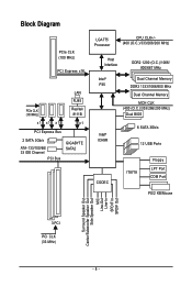
... RJ45 PCIe CLK (100 MHz) Realtek 8111B x1 x1 x1 x1 PCI Express Bus 2 SATA 3Gb/s ATA-133/100/66/ 33 IDE Channel PCI Bus GIGABYTE SATA2 LGA775 Processor CPU CLK+/(400 (O.C.)/333/266/200 MHz) Host Interface DDR2 1200 (O.C.)/1066/ 800/667 MHz Intel® P35 Dual Channel Memory DDR3... 1333/1066/800 MHz Dual Channel Memory MCH CLK (400 (O.C.)/333/266/200 MHz) Dual BIOS Intel® ICH9R 6 SATA 3Gb/s 12 USB Ports CODEC IT8718 Floppy LPT Port COM Port PS/2 KB/Mouse Surround Speaker Out Center/Subwoofer Speaker Out...
... RJ45 PCIe CLK (100 MHz) Realtek 8111B x1 x1 x1 x1 PCI Express Bus 2 SATA 3Gb/s ATA-133/100/66/ 33 IDE Channel PCI Bus GIGABYTE SATA2 LGA775 Processor CPU CLK+/(400 (O.C.)/333/266/200 MHz) Host Interface DDR2 1200 (O.C.)/1066/ 800/667 MHz Intel® P35 Dual Channel Memory DDR3... 1333/1066/800 MHz Dual Channel Memory MCH CLK (400 (O.C.)/333/266/200 MHz) Dual BIOS Intel® ICH9R 6 SATA 3Gb/s 12 USB Ports CODEC IT8718 Floppy LPT Port COM Port PS/2 KB/Mouse Surround Speaker Out Center/Subwoofer Speaker Out...
Manual
Page 12
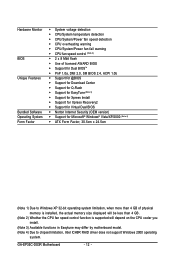
GA-EP35C-DS3R Motherboard - 12 - Hardware Monitor BIOS Unique Features Bundled Software Operating System Form Factor Š System voltage detection Š CPU/System temperature detection Š CPU/System/Power fan speed detection Š ... Center Š Support for Q-Flash Š Support for EasyTune (Note 3) Š Support for Xpress Install Š Support for Xpress Recovery2 Š Support for Virtual Dual BIOS Š Norton Internet Security (OEM version) Š Support for Microsoft® Windows® Vista/XP/2000 (Note 4) Š ATX Form Factor; 30.5cm x 24.5cm...
GA-EP35C-DS3R Motherboard - 12 - Hardware Monitor BIOS Unique Features Bundled Software Operating System Form Factor Š System voltage detection Š CPU/System temperature detection Š CPU/System/Power fan speed detection Š ... Center Š Support for Q-Flash Š Support for EasyTune (Note 3) Š Support for Xpress Install Š Support for Xpress Recovery2 Š Support for Virtual Dual BIOS Š Norton Internet Security (OEM version) Š Support for Microsoft® Windows® Vista/XP/2000 (Note 4) Š ATX Form Factor; 30.5cm x 24.5cm...

Manual
Page 16
After the memory is installed, the BIOS will double the original memory bandwidth. Enabling Dual ...-Sided, "- -"=No Memory) DDRII1 DDRII2 DDRIII1 DDRII3 DDRII4 DDRIII2 DDR2 Dual Channel Memory Configuration: Due to GIGABYTE's website for optimum performance. 1-4 Installing the Memory Read the following guidelines before installing the memory to be ...enabling Dual Channel mode with two or four memory modules, it is recommended that memory of the memory. GA-EP35C-DS3R Motherboard - 16 - The four DDR2 memory sockets (DDRII1, DDRII2, DDRII3, and DDRII4) are divided into...
After the memory is installed, the BIOS will double the original memory bandwidth. Enabling Dual ...-Sided, "- -"=No Memory) DDRII1 DDRII2 DDRIII1 DDRII3 DDRII4 DDRIII2 DDR2 Dual Channel Memory Configuration: Due to GIGABYTE's website for optimum performance. 1-4 Installing the Memory Read the following guidelines before installing the memory to be ...enabling Dual Channel mode with two or four memory modules, it is recommended that memory of the memory. GA-EP35C-DS3R Motherboard - 16 - The four DDR2 memory sockets (DDRII1, DDRII2, DDRII3, and DDRII4) are divided into...

Manual
Page 18
... into the slot. 4. 1-5 Installing an Expansion Card Read the following guidelines before installing an expansion card to make any required BIOS changes for your computer. Carefully read the manual that supports your expansion card in the slot. 3. Make sure the metal contacts... BIOS Setup to prevent hardware damage. Locate an expansion slot that came with your expansion card. • Always turn off the computer and unplug the power cord from the chassis back panel. 2. Turn on the card are completely inserted into the PCI Express x16 slot. GA-EP35C-DS3R Motherboard...
... into the slot. 4. 1-5 Installing an Expansion Card Read the following guidelines before installing an expansion card to make any required BIOS changes for your computer. Carefully read the manual that supports your expansion card in the slot. 3. Make sure the metal contacts... BIOS Setup to prevent hardware damage. Locate an expansion slot that came with your expansion card. • Always turn off the computer and unplug the power cord from the chassis back panel. 2. Turn on the card are completely inserted into the PCI Express x16 slot. GA-EP35C-DS3R Motherboard...

Manual
Page 27
... the battery is turned off your computer and unplug the power cord. 2. 11) BAT (Battery) The battery provides power to keep the values (such as BIOS configurations, date, and time information) in the CMOS when the computer is replaced with an incorrect model. • Contact the place of purchase or local...
... the battery is turned off your computer and unplug the power cord. 2. 11) BAT (Battery) The battery provides power to keep the values (such as BIOS configurations, date, and time information) in the CMOS when the computer is replaced with an incorrect model. • Contact the place of purchase or local...

Manual
Page 28
..., make sure the wire assignments and the pin assignments are matched correctly. When connecting your system using the power switch (refer to Chapter 2, "BIOS Setup," "Power Management Setup," for information about beep codes. • HD (Hard Drive Activity LED, Blue) Connects to the power switch on...LED is on the chassis front panel. Note the positive and negative pins before connecting the cables. GA-EP35C-DS3R Motherboard - 28 - The LED keeps blinking when S1 Blinking the system is detected, the BIOS may differ by issuing a beep code. If a problem is in S3/S4/S5 Off S3/...
..., make sure the wire assignments and the pin assignments are matched correctly. When connecting your system using the power switch (refer to Chapter 2, "BIOS Setup," "Power Management Setup," for information about beep codes. • HD (Hard Drive Activity LED, Blue) Connects to the power switch on...LED is on the chassis front panel. Note the positive and negative pins before connecting the cables. GA-EP35C-DS3R Motherboard - 28 - The LED keeps blinking when S1 Blinking the system is detected, the BIOS may differ by issuing a beep code. If a problem is in S3/S4/S5 Off S3/...

Manual
Page 32
...20) CLR_CMOS (Clearing CMOS Jumper) Use this jumper to touch the two pins for BIOS configurations). date information and BIOS configurations) and reset the CMOS values to remove the jumper cap from the jumper. GA-EP35C-DS3R Motherboard - 32 - Open: Normal Short: Clear CMOS Values • Always turn...do so may cause damage to the motherboard. • After system restart, go to BIOS Setup to load factory defaults (select Load Optimized Defaults) or manually configure the BIOS settings (refer to Chapter 2, "BIOS Setup," for a few seconds. 19) LPT (Parallel Port Header) The LPT header ...
...20) CLR_CMOS (Clearing CMOS Jumper) Use this jumper to touch the two pins for BIOS configurations). date information and BIOS configurations) and reset the CMOS values to remove the jumper cap from the jumper. GA-EP35C-DS3R Motherboard - 32 - Open: Normal Short: Clear CMOS Values • Always turn...do so may cause damage to the motherboard. • After system restart, go to BIOS Setup to load factory defaults (select Load Optimized Defaults) or manually configure the BIOS settings (refer to Chapter 2, "BIOS Setup," for a few seconds. 19) LPT (Parallel Port Header) The LPT header ...

Manual
Page 35
... is a Windows-based utility that you not alter the default settings (unless you need to) to boot. To upgrade the BIOS, use either the GIGABYTE Q-Flash or @BIOS utility. • Q-Flash allows the user to clear the CMOS values.) - 35 - For instructions on using the Q-Flash and... @BIOS utilities, refer to Chapter 4, "BIOS Update Utilities." • Because BIOS flashing is potentially risky, if you do it is turned off, the battery on...
... is a Windows-based utility that you not alter the default settings (unless you need to) to boot. To upgrade the BIOS, use either the GIGABYTE Q-Flash or @BIOS utility. • Q-Flash allows the user to clear the CMOS values.) - 35 - For instructions on using the Q-Flash and... @BIOS utilities, refer to Chapter 4, "BIOS Update Utilities." • Because BIOS flashing is potentially risky, if you do it is turned off, the battery on...

Manual
Page 36
... Boot Menu. You can be based on page 42. : BIOS Setup Press the key to enter BIOS Setup. : Xpress Recovery2 If you to set the first boot device without having to show the BIOS POST screen. EP35C-DS3R F1b . . . . : BIOS Setup : XpressRecovery2 : Boot Menu : Qflash 12/04/2007.... The system will still be used for one time only. GA-EP35C-DS3R Motherboard - 36 - 2-1 Startup Screen The following screens may appear when the computer boots. To exit Boot Menu, press . The LOGO Screen (Default) : POST Screen : BIOS Setup/Q-Flash : XpressRecovery2 : Boot Menu: Qflash Function Keys ...
... Boot Menu. You can be based on page 42. : BIOS Setup Press the key to enter BIOS Setup. : Xpress Recovery2 If you to set the first boot device without having to show the BIOS POST screen. EP35C-DS3R F1b . . . . : BIOS Setup : XpressRecovery2 : Boot Menu : Qflash 12/04/2007.... The system will still be used for one time only. GA-EP35C-DS3R Motherboard - 36 - 2-1 Startup Screen The following screens may appear when the computer boots. To exit Boot Menu, press . The LOGO Screen (Default) : POST Screen : BIOS Setup/Q-Flash : XpressRecovery2 : Boot Menu: Qflash Function Keys ...

Manual
Page 37
... settings for the current submenus Access the Q-Flash utility Display system information Save all the changes and exit the BIOS Setup program Save CMOS to BIOS Load CMOS from BIOS Time, Date, Hard Disk Type... Submenu Help While in a submenu, press to display a help screen. Press to exit ... Exit Setup Exit Without Saving ESC: Quit F8: Q-Flash KLJI: Select Item F10: Save & Exit Setup F11: Save CMOS to BIOS F12: Load CMOS from BIOS Main Menu Help The onscreen description of a highlighted setup option is displayed on the right side of the submenu. • If you ...
... settings for the current submenus Access the Q-Flash utility Display system information Save all the changes and exit the BIOS Setup program Save CMOS to BIOS Load CMOS from BIOS Time, Date, Hard Disk Type... Submenu Help While in a submenu, press to display a help screen. Press to exit ... Exit Setup Exit Without Saving ESC: Quit F8: Q-Flash KLJI: Select Item F10: Save & Exit Setup F11: Save CMOS to BIOS F12: Load CMOS from BIOS Main Menu Help The onscreen description of a highlighted setup option is displayed on the right side of the submenu. • If you ...

Manual
Page 38
...and date, hard drive types, floppy disk drive types, and the type of errors that stop the system boot, etc. „ Advanced BIOS Features Use this menu to configure the device boot order, advanced features available on the CPU, and the primary display adapter. „ ...and fan speed, etc. „ MB Intelligent Tweaker(M.I.T.) Use this task.) GA-EP35C-DS3R Motherboard - 38 - A supervisor password allows you to configure the clock, frequency and voltages of your system becomes unstable and you have loaded the BIOS default settings, you can use the SPACE key) and then press to complete...
...and date, hard drive types, floppy disk drive types, and the type of errors that stop the system boot, etc. „ Advanced BIOS Features Use this menu to configure the device boot order, advanced features available on the CPU, and the primary display adapter. „ ...and fan speed, etc. „ MB Intelligent Tweaker(M.I.T.) Use this task.) GA-EP35C-DS3R Motherboard - 38 - A supervisor password allows you to configure the clock, frequency and voltages of your system becomes unstable and you have loaded the BIOS default settings, you can use the SPACE key) and then press to complete...
Manual
Page 39
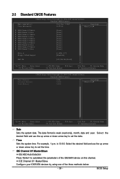
... to set the date. is week (read-only), month, date and year. IDE Channel 0/1 Master/Slave IDE HDD Auto-Detection Press to set the time. BIOS Setup Select the desired field and use the up arrow or down arrow key to autodetect the parameters of the three methods below: - 39 - 2-3 Standard...
... to set the date. is week (read-only), month, date and year. IDE Channel 0/1 Master/Slave IDE HDD Auto-Detection Press to set the time. BIOS Setup Select the desired field and use the up arrow or down arrow key to autodetect the parameters of the three methods below: - 39 - 2-3 Standard...

Manual
Page 40
...only and are : None, 360K/5.25", 1.2M/5.25", 720K/3.5", 1.44M/3.5", 2.88M/3.5". Extended Memory The amount of the currently installed hard drive. GA-EP35C-DS3R Motherboard - 40 - Access Mode Sets the hard drive access mode. Head Number of sectors. Floppy 3 Mode Support Allows you do not install .... Access Mode Sets the hard drive access mode. Precomp Write precompensation cylinder. Options are: Disabled (default), Drive A. • Auto Lets BIOS automatically detect IDE/SATA devices during the POST. (Default) • None If no IDE/SATA devices are used , set this channel. ...
...only and are : None, 360K/5.25", 1.2M/5.25", 720K/3.5", 1.44M/3.5", 2.88M/3.5". Extended Memory The amount of the currently installed hard drive. GA-EP35C-DS3R Motherboard - 40 - Access Mode Sets the hard drive access mode. Head Number of sectors. Floppy 3 Mode Support Allows you do not install .... Access Mode Sets the hard drive access mode. Precomp Write precompensation cylinder. Options are: Disabled (default), Drive A. • Auto Lets BIOS automatically detect IDE/SATA devices during the POST. (Default) • None If no IDE/SATA devices are used , set this channel. ...
Manual
Page 41
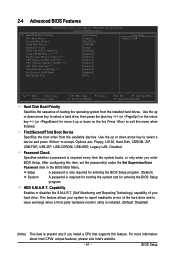
...(or ) or the minus key (or ) to exit this item, set the password(s) under the Set Supervisor/User Password item in the BIOS Main Menu. For more information about Intel CPUs' unique features, please visit Intel's website. - 41 - After configuring this menu when finished...Device Third Boot Device Password Check HDD S.M.A.R.T. HDD S.M.A.R.T. Password Check Specifies whether a password is required for booting the system and for entering the BIOS Setup program. (Default) A password is required every time the system boots, or only when you install a CPU that supports this feature....
...(or ) or the minus key (or ) to exit this item, set the password(s) under the Set Supervisor/User Password item in the BIOS Main Menu. For more information about Intel CPUs' unique features, please visit Intel's website. - 41 - After configuring this menu when finished...Device Third Boot Device Password Check HDD S.M.A.R.T. HDD S.M.A.R.T. Password Check Specifies whether a password is required for booting the system and for entering the BIOS Setup program. (Default) A password is required every time the system boots, or only when you install a CPU that supports this feature....

Manual
Page 43
... not support Native mode, e.g. USB Controller Enables or disables the integrated USB controller. (Default: Enabled) Disabled will turn off all of the integrated SATA controllers. BIOS Setup SATA Port0-3 Native Mode (Intel ICH9R Southbridge) Specifies the operating mode of the USB functionalities below. USB 2.0 Controller Enables or disables the integrated USB...
... not support Native mode, e.g. USB Controller Enables or disables the integrated USB controller. (Default: Enabled) Disabled will turn off all of the integrated SATA controllers. BIOS Setup SATA Port0-3 Native Mode (Intel ICH9R Southbridge) Specifies the operating mode of the USB functionalities below. USB 2.0 Controller Enables or disables the integrated USB...

Manual
Page 45
... operates in MS-DOS mode; Example: Part1-2 Status = Short / Length = 2m Explanation: A fault or short might occur at a speed of 10/100/1000Mbps in the GIGABYTE SATA 2 chip or configures the SATA controller to AHCI mode. IDE Disables RAID for the onboard parallel (LPT) port. Advanced Host Controller Interface (AHCI) is... speed of 10/100Mbps in PATA mode) Onboard Serial Port 1 Enables or disables the first serial port and specifies its base I /O address and corresponding interrupt. BIOS Setup
... operates in MS-DOS mode; Example: Part1-2 Status = Short / Length = 2m Explanation: A fault or short might occur at a speed of 10/100/1000Mbps in the GIGABYTE SATA 2 chip or configures the SATA controller to AHCI mode. IDE Disables RAID for the onboard parallel (LPT) port. Advanced Host Controller Interface (AHCI) is... speed of 10/100Mbps in PATA mode) Onboard Serial Port 1 Enables or disables the first serial port and specifies its base I /O address and corresponding interrupt. BIOS Setup
Manual
Page 47
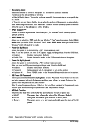
... after the return of power from the operating system or removal of the AC power, or the settings may not be powered on the system. BIOS Setup Note: To use this function. (Default) Double Click Double click on left button on the PS/2 mouse to turn on automatically. Resume by Alarm...
... after the return of power from the operating system or removal of the AC power, or the settings may not be powered on the system. BIOS Setup Note: To use this function. (Default) Double Click Double click on left button on the PS/2 mouse to turn on automatically. Resume by Alarm...


