Manual
Page 1
GA-EP35-DS3L/ GA-EP35-S3L LGA775 socket motherboard for Intel® CoreTM processor family/ Intel® Pentium® processor family/Intel® Celeron® processor family User's Manual Rev. 1002 12ME-EP35DS3L-1002R
GA-EP35-DS3L/ GA-EP35-S3L LGA775 socket motherboard for Intel® CoreTM processor family/ Intel® Pentium® processor family/Intel® Celeron® processor family User's Manual Rev. 1002 12ME-EP35DS3L-1002R

Manual
Page 2
Motherboard GA-EP35-DS3L/GA-EP35-S3L Feb. 1, 2008 Motherboard GA-EP35-DS3L/ GA-EP35-S3L Feb. 1, 2008
Motherboard GA-EP35-DS3L/GA-EP35-S3L Feb. 1, 2008 Motherboard GA-EP35-DS3L/ GA-EP35-S3L Feb. 1, 2008
Manual
Page 3
... information. The logo is 1.0. sive global distributor of the motherboard is exclusively licensed to their respective owners. Check your motherboard looks like this manual are legally registered to GIGABYTE UNITED INC. GIGABYTE UNITED INC. Changes to use of this manual may be... For quick set-up of this manual may be made by any form or by GIGABYTE without GIGABYTE's prior written permission. For example, "REV: 1.0" means the revision of GIGABYTE branded motherboards. Copyright © 2008 GIGA-BYTE TECHNOLOGY CO., LTD. Example: The trademarks mentioned ...
... information. The logo is 1.0. sive global distributor of the motherboard is exclusively licensed to their respective owners. Check your motherboard looks like this manual are legally registered to GIGABYTE UNITED INC. GIGABYTE UNITED INC. Changes to use of this manual may be... For quick set-up of this manual may be made by any form or by GIGABYTE without GIGABYTE's prior written permission. For example, "REV: 1.0" means the revision of GIGABYTE branded motherboards. Copyright © 2008 GIGA-BYTE TECHNOLOGY CO., LTD. Example: The trademarks mentioned ...

Manual
Page 4
Table of Contents Box Contents ...6 OptionalItems...6 GA-EP35-DS3L/S3L Motherboard Layout 7 Block Diagram...8 Chapter 1 Hardware Installation 9 1-1 Installation Precautions 9 1-2 Product Specifications 10 1-3 Installing the CPU and CPU Cooler 13 1-3-1 Installing the CPU 13 1-3-2 Installing the CPU ...
Table of Contents Box Contents ...6 OptionalItems...6 GA-EP35-DS3L/S3L Motherboard Layout 7 Block Diagram...8 Chapter 1 Hardware Installation 9 1-1 Installation Precautions 9 1-2 Product Specifications 10 1-3 Installing the CPU and CPU Cooler 13 1-3-1 Installing the CPU 13 1-3-2 Installing the CPU ...

Manual
Page 6
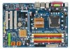
The box contents are for reference only. Box Contents GA-EP35-DS3L or GA-EP35-S3L motherboard Motherboard driver disk User's Manual Quick Installation Guide Intel® LGA775 CPU Installation Guide One IDE cable and one floppy disk drive cable Two SATA ...3Gb/s cables I/O Shield • The box contents above are subject to change without notice. • The motherboard image is for reference only and the ...
The box contents are for reference only. Box Contents GA-EP35-DS3L or GA-EP35-S3L motherboard Motherboard driver disk User's Manual Quick Installation Guide Intel® LGA775 CPU Installation Guide One IDE cable and one floppy disk drive cable Two SATA ...3Gb/s cables I/O Shield • The box contents above are subject to change without notice. • The motherboard image is for reference only and the ...
Manual
Page 7
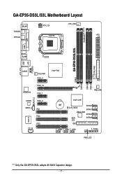
GA-EP35-DS3L/S3L Motherboard Layout KB_MS ATX_12V CPU_FAN COAXIAL OPTICAL LGA775 ATX PHASELED COM LPT DDRII1 GA-EP35-DS3L/S3L R_USB SYS_FAN2 USB LAN F_AUDIO AUDIO SYS_FAN1 PCIE_3 RTL8111B PCIE_16 PCIE_1 SPDIF_O CODEC PCIE_2 SPDIF_I PCI1 PCI2 IT8718 PCI3 CD_IN Intel® P35 FDD DDRII3 DDRII4 DDRII2 PWR_FAN Intel® ICH9 BAT CLR_CMOS SATAII0 SATAII1 JMicron 368 SATAII4 BIOS SATAII5 IDE1 F_USB3 F_USB2 F_USB1 CI F_PANEL PWR_LED "*" Only the GA-EP35-DS3L adopts All-Solid Capacitor design. - 7 -
GA-EP35-DS3L/S3L Motherboard Layout KB_MS ATX_12V CPU_FAN COAXIAL OPTICAL LGA775 ATX PHASELED COM LPT DDRII1 GA-EP35-DS3L/S3L R_USB SYS_FAN2 USB LAN F_AUDIO AUDIO SYS_FAN1 PCIE_3 RTL8111B PCIE_16 PCIE_1 SPDIF_O CODEC PCIE_2 SPDIF_I PCI1 PCI2 IT8718 PCI3 CD_IN Intel® P35 FDD DDRII3 DDRII4 DDRII2 PWR_FAN Intel® ICH9 BAT CLR_CMOS SATAII0 SATAII1 JMicron 368 SATAII4 BIOS SATAII5 IDE1 F_USB3 F_USB2 F_USB1 CI F_PANEL PWR_LED "*" Only the GA-EP35-DS3L adopts All-Solid Capacitor design. - 7 -

Manual
Page 9
...ESD wrist strap, keep your hands dry and first touch a metal object to eliminate static electricity. • Prior to installing the motherboard, please have it on top of an antistatic pad or within an electrostatic shielding container. • Before unplugging the power supply ...8226; It is best to the use of electrostatic discharge (ESD). These stickers are connected tightly and securely. • When handling the motherboard, avoid touching any installation steps or have a problem related to wear an electrostatic discharge (ESD) wrist strap when handling electronic components such as...
...ESD wrist strap, keep your hands dry and first touch a metal object to eliminate static electricity. • Prior to installing the motherboard, please have it on top of an antistatic pad or within an electrostatic shielding container. • Before unplugging the power supply ...8226; It is best to the use of electrostatic discharge (ESD). These stickers are connected tightly and securely. • When handling the motherboard, avoid touching any installation steps or have a problem related to wear an electrostatic discharge (ESD) wrist strap when handling electronic components such as...

Manual
Page 10
GA-EP35-DS3L/S3L Motherboard - 10 - 1-2 Product Specifications CPU Front Side Bus Chipset Memory Audio LAN...Extreme Edition/Intel® Pentium® 4 processor/ Intel® Celeron® processor in the LGA 775 package (Go to GIGABYTE's website for the latest CPU support list.) Š L2 cache varies with CPU Š 1333/1066/800 MHz FSB &#... (Note 1) Š Dual channel memory architecture Š Support for DDR2 1066/800/667 MHz memory modules (Go to GIGABYTE's website for the latest memory support list.) Š Realtek ALC888 codec Š High Definition Audio Š 2/4/5.1/7.1-channel &#...
GA-EP35-DS3L/S3L Motherboard - 10 - 1-2 Product Specifications CPU Front Side Bus Chipset Memory Audio LAN...Extreme Edition/Intel® Pentium® 4 processor/ Intel® Celeron® processor in the LGA 775 package (Go to GIGABYTE's website for the latest CPU support list.) Š L2 cache varies with CPU Š 1333/1066/800 MHz FSB &#... (Note 1) Š Dual channel memory architecture Š Support for DDR2 1066/800/667 MHz memory modules (Go to GIGABYTE's website for the latest memory support list.) Š Realtek ALC888 codec Š High Definition Audio Š 2/4/5.1/7.1-channel &#...
Manual
Page 12
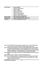
GA-EP35-DS3L/S3L Motherboard - 12 - Unique Features Bundled Software Operating System Form Factor Š Support for @BIOS Š Support for Download Center Š Support for Q-Flash Š Support for ... 3) Whether the CPU fan speed control function is supported will depend on the CPU cooler you install. (Note 4) Available functions in Easytune may differ by motherboard model. (Note 5) Due to the hardware limitation, you must install the Intel® CoreTM 2 Extreme/ CoreTM 2 Quad/ CoreTM 2 Duo/ Pentium Dual-Core/ Celeron Dual-Core...
GA-EP35-DS3L/S3L Motherboard - 12 - Unique Features Bundled Software Operating System Form Factor Š Support for @BIOS Š Support for Download Center Š Support for Q-Flash Š Support for ... 3) Whether the CPU fan speed control function is supported will depend on the CPU cooler you install. (Note 4) Available functions in Easytune may differ by motherboard model. (Note 5) Due to the hardware limitation, you must install the Intel® CoreTM 2 Extreme/ CoreTM 2 Quad/ CoreTM 2 Duo/ Pentium Dual-Core/ Celeron Dual-Core...
Manual
Page 13
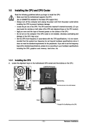
... and damage of the CPU may occur. • Set the CPU host frequency in accordance with the CPU specifications. mended that the motherboard supports the CPU. (Go to GIGABYTE's website for the peripherals. The CPU cannot be set the frequency beyond hardware specifications since it does not meet the standard requirements for... the standard specifications, please do so according to prevent hardware damage. • Locate the pin one of the CPU. Locate the alignment keys on the motherboard CPU socket and the notches on the CPU - 13 -
... and damage of the CPU may occur. • Set the CPU host frequency in accordance with the CPU specifications. mended that the motherboard supports the CPU. (Go to GIGABYTE's website for the peripherals. The CPU cannot be set the frequency beyond hardware specifications since it does not meet the standard requirements for... the standard specifications, please do so according to prevent hardware damage. • Locate the pin one of the CPU. Locate the alignment keys on the motherboard CPU socket and the notches on the CPU - 13 -

Manual
Page 14
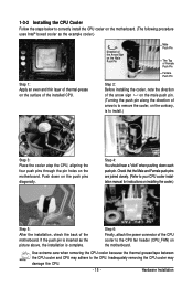
... socket. B. Follow the steps below to the CPU. Step 3: Lift the metal load plate on the CPU socket. GA-EP35-DS3L/S3L Motherboard - 14 - Step 4: Hold the CPU with the socket alignment keys) and gently insert the CPU into position. Before installing the CPU, make sure to turn ...
... socket. B. Follow the steps below to the CPU. Step 3: Lift the metal load plate on the CPU socket. GA-EP35-DS3L/S3L Motherboard - 14 - Step 4: Hold the CPU with the socket alignment keys) and gently insert the CPU into position. Before installing the CPU, make sure to turn ...
Manual
Page 15
...the CPU cooler to your CPU cooler installation manual for instructions on installing the cooler.) Step 5: After the installation, check the back of the motherboard. Direction of the Arrow Sign on the Male Push Pin Male Push Pin The Top of Female Push Pin Female Push Pin Step 2: Before ...CPU cooler and CPU may damage the CPU. - 15 - 1-3-2 Installing the CPU Cooler Follow the steps below to correctly install the CPU cooler on the motherboard. (The following procedure uses Intel® boxed cooler as the picture above, the installation is to install.) Step 3: Place the cooler atop the CPU,...
...the CPU cooler to your CPU cooler installation manual for instructions on installing the cooler.) Step 5: After the installation, check the back of the motherboard. Direction of the Arrow Sign on the Male Push Pin Male Push Pin The Top of Female Push Pin Female Push Pin Step 2: Before ...CPU cooler and CPU may damage the CPU. - 15 - 1-3-2 Installing the CPU Cooler Follow the steps below to correctly install the CPU cooler on the motherboard. (The following procedure uses Intel® boxed cooler as the picture above, the installation is to install.) Step 3: Place the cooler atop the CPU,...
Manual
Page 16
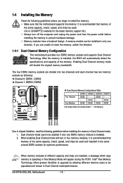
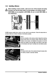
... DDRII2 DDRII3 DDRII4 Due to install the memory: • Make sure that memory of different capacity and chips are unable to GIGABYTE's website for optimum performance. It is operating in the same colored DDR2 sockets for the latest memory support list.) • Always... be used . (Go to insert the memory, switch the direction. 1-4-1 Dual Channel Memory Configuration This motherboard provides four DDR2 memory sockets and supports Dual Channel Technology. GA-EP35-DS3L/S3L Motherboard - 16 - When enabling Dual Channel mode with two or four memory modules, it is installed. ...
... DDRII2 DDRII3 DDRII4 Due to install the memory: • Make sure that memory of different capacity and chips are unable to GIGABYTE's website for optimum performance. It is operating in the same colored DDR2 sockets for the latest memory support list.) • Always... be used . (Go to insert the memory, switch the direction. 1-4-1 Dual Channel Memory Configuration This motherboard provides four DDR2 memory sockets and supports Dual Channel Technology. GA-EP35-DS3L/S3L Motherboard - 16 - When enabling Dual Channel mode with two or four memory modules, it is installed. ...
Manual
Page 17
... one direction. DDR2 DIMMs are not compatible to DDR DIMMs. Be sure to install DDR2 DIMMs on the socket. Place the memory module on this motherboard. Step 2: The clips at both ends of the socket will snap into the memory socket. Follow the steps below to the memory module. Notch DDR2...
... one direction. DDR2 DIMMs are not compatible to DDR DIMMs. Be sure to install DDR2 DIMMs on the socket. Place the memory module on this motherboard. Step 2: The clips at both ends of the socket will snap into the memory socket. Follow the steps below to the memory module. Notch DDR2...

Manual
Page 18
... system. Remove the metal slot cover from the slot. Secure the card's metal bracket to install an expansion card: • Make sure the motherboard supports the expansion card. GA-EP35-DS3L/S3L Motherboard - 18 - Locate an expansion slot that came with your expansion card. • Always turn off the computer and unplug the power cord...
... system. Remove the metal slot cover from the slot. Secure the card's metal bracket to install an expansion card: • Make sure the motherboard supports the expansion card. GA-EP35-DS3L/S3L Motherboard - 18 - Locate an expansion slot that came with your expansion card. • Always turn off the computer and unplug the power cord...

Manual
Page 19
...-45 LAN Port The Gigabit Ethernet LAN port provides Internet connection at up to connect a PS/2 keyboard. Do not rock it straight out from the motherboard. • When removing the cable, pull it side to side to prevent an electrical short inside the cable connector. - 19 - Before using this feature, ensure...
...-45 LAN Port The Gigabit Ethernet LAN port provides Internet connection at up to connect a PS/2 keyboard. Do not rock it straight out from the motherboard. • When removing the cable, pull it side to side to prevent an electrical short inside the cable connector. - 19 - Before using this feature, ensure...
Manual
Page 20
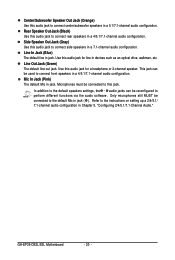
... configuration. Microphones must be reconfigured to the instructions on setting up a 2/4/5.1/ 7.1-channel audio configuration in jack ( ). Mic In Jack (Pink) The default Mic in jack. GA-EP35-DS3L/S3L Motherboard - 20 -
... configuration. Microphones must be reconfigured to the instructions on setting up a 2/4/5.1/ 7.1-channel audio configuration in jack ( ). Mic In Jack (Pink) The default Mic in jack. GA-EP35-DS3L/S3L Motherboard - 20 -

Manual
Page 21
...) CD_IN 14) SPDIF_I 15) SPDIF_O 16) F_USB1/F_USB2/F_USB3 17) CI 18) CLR_CMOS 19) BAT 20) PHASELED Read the following guidelines before turning on the motherboard. - 21 - Unplug the power cord from the power outlet to prevent damage to the devices. • After installing the device and before connecting external devices...
...) CD_IN 14) SPDIF_I 15) SPDIF_O 16) F_USB1/F_USB2/F_USB3 17) CI 18) CLR_CMOS 19) BAT 20) PHASELED Read the following guidelines before turning on the motherboard. - 21 - Unplug the power cord from the power outlet to prevent damage to the devices. • After installing the device and before connecting external devices...

Manual
Page 22
... supply cable into pins under the protective cover when using a 2x12 power supply, remove the protective cover from the main power connector on the motherboard. 1/2) ATX_12V/ATX (2x2 12V Power Connector and 2x12 Main Power Connector) With the use of the power connector, the power supply can lead...-12V GND PS_ON(soft On/Off) GND GND GND -5V +5V +5V +5V (Only for 2x12-pinATX) GND (Only for 2x12-pin ATX) GA-EP35-DS3L/S3L Motherboard - 22 - Before connecting the power connector, first make sure the power supply is recommended that a power supply that can withstand high power consumption be ...
... supply cable into pins under the protective cover when using a 2x12 power supply, remove the protective cover from the main power connector on the motherboard. 1/2) ATX_12V/ATX (2x2 12V Power Connector and 2x12 Main Power Connector) With the use of the power connector, the power supply can lead...-12V GND PS_ON(soft On/Off) GND GND GND -5V +5V +5V +5V (Only for 2x12-pinATX) GND (Only for 2x12-pin ATX) GA-EP35-DS3L/S3L Motherboard - 22 - Before connecting the power connector, first make sure the power supply is recommended that a power supply that can withstand high power consumption be ...
Manual
Page 23
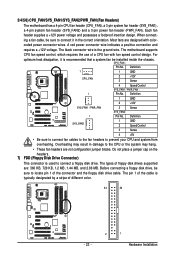
.... CPU_FAN : Pin No. Overheating may hang. • These fan headers are not configuration jumper blocks. Hardware Installation The motherboard supports CPU fan speed control, which requires the use of the connector and the floppy disk drive cable. The types of ... CPU fan with color- Definition 1 GND 2 +12V SYS_FAN1 / PWR_FAN 3 Sense SYS_FAN2: 1 Pin No. 3/4/5/6) CPU_FAN/SYS_FAN1/SYS_FAN2/PWR_FAN (Fan Headers) The motherboard has a 4-pin CPU fan header (CPU_FAN), a 3-pin system fan header (SYS_FAN1), a 4-pin system fan header (SYS_FAN2) and a 3-pin power fan header...
.... CPU_FAN : Pin No. Overheating may hang. • These fan headers are not configuration jumper blocks. Hardware Installation The motherboard supports CPU fan speed control, which requires the use of the connector and the floppy disk drive cable. The types of ... CPU fan with color- Definition 1 GND 2 +12V SYS_FAN1 / PWR_FAN 3 Sense SYS_FAN2: 1 Pin No. 3/4/5/6) CPU_FAN/SYS_FAN1/SYS_FAN2/PWR_FAN (Fan Headers) The motherboard has a 4-pin CPU fan header (CPU_FAN), a 3-pin system fan header (SYS_FAN1), a 4-pin system fan header (SYS_FAN2) and a 3-pin power fan header...


