Manual
Page 1
GA-EP35-DS3R/ GA-EP35-DS3 LGA775 socket motherboard for Intel® CoreTM processor family/ Intel® Pentium® processor family/Intel® Celeron® processor family User's Manual Rev. 2101 12ME-EP35DS3R-2101R
GA-EP35-DS3R/ GA-EP35-DS3 LGA775 socket motherboard for Intel® CoreTM processor family/ Intel® Pentium® processor family/Intel® Celeron® processor family User's Manual Rev. 2101 12ME-EP35DS3R-2101R
Manual
Page 2
Motherboard GA-EP35-DS3R/DS3 Dec. 21, 2007 Motherboard GA-EP35-DS3R/DS3 Dec. 21, 2007
Motherboard GA-EP35-DS3R/DS3 Dec. 21, 2007 Motherboard GA-EP35-DS3R/DS3 Dec. 21, 2007
Manual
Page 3
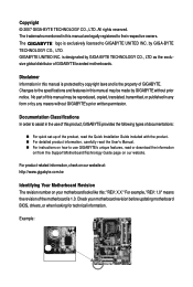
...legally registered to the specifications and features in this : "REV: X.X." Example: by GIGABYTE without GIGABYTE's prior written permission. Changes to their respective owners. Check your motherboard looks like this manual may be made by GIGA-BYTE TECHNOLOGY CO., LTD. For ...or download the information on/from the Support\Motherboard\Technology Guide page on your motherboard revision before updating motherboard BIOS, drivers, or when looking for technical information. is the property of GIGABYTE branded motherboards. Disclaimer Information in any form or by ...
...legally registered to the specifications and features in this : "REV: X.X." Example: by GIGABYTE without GIGABYTE's prior written permission. Changes to their respective owners. Check your motherboard looks like this manual may be made by GIGA-BYTE TECHNOLOGY CO., LTD. For ...or download the information on/from the Support\Motherboard\Technology Guide page on your motherboard revision before updating motherboard BIOS, drivers, or when looking for technical information. is the property of GIGABYTE branded motherboards. Disclaimer Information in any form or by ...

Manual
Page 4
Table of Contents Box Contents ...6 OptionalItems ...6 GA-EP35-DS3R/DS3 Motherboard Layout 7 Block Diagram ...8 Chapter 1 Hardware Installation 9 1-1 Installation Precautions 9 1-2 Product Specifications 10 1-3 Installing the CPU and CPU Cooler 13 1-3-1 Installing the CPU 13 1-3-2 Installing the CPU ...
Table of Contents Box Contents ...6 OptionalItems ...6 GA-EP35-DS3R/DS3 Motherboard Layout 7 Block Diagram ...8 Chapter 1 Hardware Installation 9 1-1 Installation Precautions 9 1-2 Product Specifications 10 1-3 Installing the CPU and CPU Cooler 13 1-3-1 Installing the CPU 13 1-3-2 Installing the CPU ...
Manual
Page 6
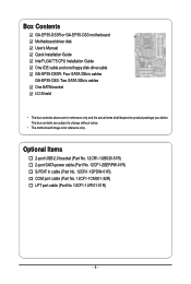
... 12CF1-1CM001-32R) LPT port cable (Part No. 12CF1-1LP001-01R) - 6 - The box contents are for reference only. Box Contents GA-EP35-DS3R or GA-EP35-DS3 motherboard Motherboard driver disk User's Manual Quick Installation Guide Intel® LGA775 CPU Installation Guide One IDE cable and one floppy disk drive cable... GA-EP35-DS3R: Four SATA 3Gb/s cables GA-EP35-DS3: Two SATA 3Gb/s cables One SATA bracket I/O Shield • The box contents above are subject to change without notice. • The motherboard image is for reference only and the actual ...
... 12CF1-1CM001-32R) LPT port cable (Part No. 12CF1-1LP001-01R) - 6 - The box contents are for reference only. Box Contents GA-EP35-DS3R or GA-EP35-DS3 motherboard Motherboard driver disk User's Manual Quick Installation Guide Intel® LGA775 CPU Installation Guide One IDE cable and one floppy disk drive cable... GA-EP35-DS3R: Four SATA 3Gb/s cables GA-EP35-DS3: Two SATA 3Gb/s cables One SATA bracket I/O Shield • The box contents above are subject to change without notice. • The motherboard image is for reference only and the actual ...
Manual
Page 7
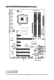
Only for GA-EP35-DS3R. GA-EP35-DS3R/DS3 Motherboard Layout KB_MS RCA_SPDIF R_USB1 R_USB2 R_USB3 ATX_12V LGA775 PHASE LED CPU_FAN ATX GA-EP35-DS3R/DS3 DDRII1 USB_LAN F_AUDIO AUDIO SYS_FAN1 PCIE_3 PCIE_16 RTL8111B PCIE_1 SPDIF_O PCIE_2 CODEC PCI1 SPDIF_I PCI2 IT8718 CD_IN PCI3 COMA Intel® P35 FDD DDRII3 DDRII4 DDRII2 PWR_FAN BATTERY Intel® ICH9R Intel® ICH9 SATAII2 CLR_CMOS SATAII3 GSATAII0 GIGABYTE SATA2 GSATAII1 SATAII0 SATAII1 SATAII4 SATAII5 IDE1 F_USB2 F_USB1 M_BIOS CI F_PANEL LPT B_BIOS PWR_LED SYS_FAN2 Only for GA-EP35-DS3. - 7 -
Only for GA-EP35-DS3R. GA-EP35-DS3R/DS3 Motherboard Layout KB_MS RCA_SPDIF R_USB1 R_USB2 R_USB3 ATX_12V LGA775 PHASE LED CPU_FAN ATX GA-EP35-DS3R/DS3 DDRII1 USB_LAN F_AUDIO AUDIO SYS_FAN1 PCIE_3 PCIE_16 RTL8111B PCIE_1 SPDIF_O PCIE_2 CODEC PCI1 SPDIF_I PCI2 IT8718 CD_IN PCI3 COMA Intel® P35 FDD DDRII3 DDRII4 DDRII2 PWR_FAN BATTERY Intel® ICH9R Intel® ICH9 SATAII2 CLR_CMOS SATAII3 GSATAII0 GIGABYTE SATA2 GSATAII1 SATAII0 SATAII1 SATAII4 SATAII5 IDE1 F_USB2 F_USB1 M_BIOS CI F_PANEL LPT B_BIOS PWR_LED SYS_FAN2 Only for GA-EP35-DS3. - 7 -

Manual
Page 9
...manual and follow these procedures: • Prior to the use of electrostatic discharge (ESD). Chapter 1 Hardware Installation 1-1 Installation Precautions The motherboard contains numerous delicate electronic circuits and components which can lead to damage to system components as well as physical harm to the user. ...for warranty validation. • Always remove the AC power by your hardware components are connected. • To prevent damage to the motherboard, do not have an ESD wrist strap, keep your hands dry and first touch a metal object to eliminate static electricity. •...
...manual and follow these procedures: • Prior to the use of electrostatic discharge (ESD). Chapter 1 Hardware Installation 1-1 Installation Precautions The motherboard contains numerous delicate electronic circuits and components which can lead to damage to system components as well as physical harm to the user. ...for warranty validation. • Always remove the AC power by your hardware components are connected. • To prevent damage to the motherboard, do not have an ESD wrist strap, keep your hands dry and first touch a metal object to eliminate static electricity. •...
Manual
Page 10
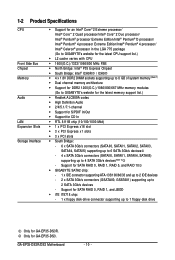
GA-EP35-DS3R/DS3 Motherboard - 10 - Only for SATA RAID 0, RAID 1, and JBOD Š iTE IT8718 chip...Š Dual channel memory architecture Š Support for DDR2 1200(O.C.)/1066/800/667 MHz memory modules (Go to GIGABYTE's website for the latest memory support list.) Š Realtek ALC889A codec Š High Definition Audio Š ...RAID 5, and RAID 10 Š GIGABYTE SATA2 chip: - 1 x IDE connector supporting ATA-133/100/66/33 and up to 2 IDE devices - 2 x SATA 3Gb/s connectors (GSATAII0, GSATAII1) supporting up to 1 floppy disk drive Only for GA-EP35-DS3R. Support for GA-EP35-DS3.
GA-EP35-DS3R/DS3 Motherboard - 10 - Only for SATA RAID 0, RAID 1, and JBOD Š iTE IT8718 chip...Š Dual channel memory architecture Š Support for DDR2 1200(O.C.)/1066/800/667 MHz memory modules (Go to GIGABYTE's website for the latest memory support list.) Š Realtek ALC889A codec Š High Definition Audio Š ...RAID 5, and RAID 10 Š GIGABYTE SATA2 chip: - 1 x IDE connector supporting ATA-133/100/66/33 and up to 2 IDE devices - 2 x SATA 3Gb/s connectors (GSATAII0, GSATAII1) supporting up to 1 floppy disk drive Only for GA-EP35-DS3R. Support for GA-EP35-DS3.
Manual
Page 12
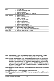
GA-EP35-DS3R/DS3 Motherboard - 12 - BIOS Unique Features Bundled Software Operating System Form Factor Š 2 x 8 Mbit... in Windows Vista only) and configure the SATA connectors for the SATA connectors (SATAII0, SATAII1, SATAII4, SATAII5) controlled by motherboard model. (Note 5) Due to Chapter 2, "BIOS Setup," "Integrated Peripherals," for details on ICH9, hot plug is supported... do not apply to the SATA connectors (GSATAII0, GSATAII1) controlled by the GIGABYTE SATA2 controller. (Refer to chipset limitation, Intel ICH9R RAID driver does not support Windows 2000 operating system.
GA-EP35-DS3R/DS3 Motherboard - 12 - BIOS Unique Features Bundled Software Operating System Form Factor Š 2 x 8 Mbit... in Windows Vista only) and configure the SATA connectors for the SATA connectors (SATAII0, SATAII1, SATAII4, SATAII5) controlled by motherboard model. (Note 5) Due to Chapter 2, "BIOS Setup," "Integrated Peripherals," for details on ICH9, hot plug is supported... do not apply to the SATA connectors (GSATAII0, GSATAII1) controlled by the GIGABYTE SATA2 controller. (Refer to chipset limitation, Intel ICH9R RAID driver does not support Windows 2000 operating system.
Manual
Page 13
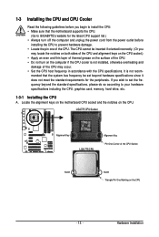
... thin layer of thermal grease on the computer if the CPU cooler is not recom- mended that the motherboard supports the CPU. (Go to GIGABYTE's website for the peripherals. Locate the alignment keys on the motherboard CPU socket and the notches on the CPU - 13 - Hardware Installation 1-3 Installing the CPU and CPU Cooler...
... thin layer of thermal grease on the computer if the CPU cooler is not recom- mended that the motherboard supports the CPU. (Go to GIGABYTE's website for the peripherals. Locate the alignment keys on the motherboard CPU socket and the notches on the CPU - 13 - Hardware Installation 1-3 Installing the CPU and CPU Cooler...

Manual
Page 14
... sure to turn off the computer and unplug the power cord from the power outlet to prevent damage to correctly install the CPU into the motherboard CPU socket. Step 5: Once the CPU is properly inserted, replace the load plate and push the CPU socket lever back into position. CPU Socket Lever... corner of the CPU socket (or you may align the CPU notches with your thumb and index fingers. B. Follow the steps below to the CPU. GA-EP35-DS3R/DS3 Motherboard - 14 -
... sure to turn off the computer and unplug the power cord from the power outlet to prevent damage to correctly install the CPU into the motherboard CPU socket. Step 5: Once the CPU is properly inserted, replace the load plate and push the CPU socket lever back into position. CPU Socket Lever... corner of the CPU socket (or you may align the CPU notches with your thumb and index fingers. B. Follow the steps below to the CPU. GA-EP35-DS3R/DS3 Motherboard - 14 -
Manual
Page 15
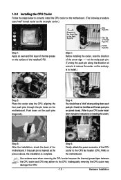
... installing the cooler, note the direction of the arrow sign on the male push pin. (Turning the push pin along the direction of the motherboard. Use extreme care when removing the CPU cooler because the thermal grease/tape between the CPU cooler and CPU may damage the CPU. - 15... the cooler atop the CPU, aligning the four push pins through the pin holes on the motherboard. 1-3-2 Installing the CPU Cooler Follow the steps below to correctly install the CPU cooler on the motherboard. (The following procedure uses Intel® boxed cooler as the picture above, the installation is...
... installing the cooler, note the direction of the arrow sign on the male push pin. (Turning the push pin along the direction of the motherboard. Use extreme care when removing the CPU cooler because the thermal grease/tape between the CPU cooler and CPU may damage the CPU. - 15... the cooler atop the CPU, aligning the four push pins through the pin holes on the motherboard. 1-3-2 Installing the CPU Cooler Follow the steps below to correctly install the CPU cooler on the motherboard. (The following procedure uses Intel® boxed cooler as the picture above, the installation is...
Manual
Page 16
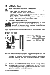
... four DDR2 memory sockets are unable to GIGABYTE's website for optimum performance. DS/SS DS/SS (SS=Single-Sided, DS=Double-Sided, "- -"=No Memory) DDRII1 DDRII2 DDRII3 DDRII4 Due to prevent hardware damage. • Memory modules have a foolproof design. GA-EP35-DS3R/DS3 Motherboard - 16 - DS/SS - - ... module is recommended that memory of different capacity and chips are installed, a message which says memory is recommended that the motherboard supports the memory. Dual Channel mode cannot be used and installed in the same colored DDR2 sockets for the latest memory ...
... four DDR2 memory sockets are unable to GIGABYTE's website for optimum performance. DS/SS DS/SS (SS=Single-Sided, DS=Double-Sided, "- -"=No Memory) DDRII1 DDRII2 DDRII3 DDRII4 Due to prevent hardware damage. • Memory modules have a foolproof design. GA-EP35-DS3R/DS3 Motherboard - 16 - DS/SS - - ... module is recommended that memory of different capacity and chips are installed, a message which says memory is recommended that the motherboard supports the memory. Dual Channel mode cannot be used and installed in the same colored DDR2 sockets for the latest memory ...

Manual
Page 17
... the memory socket. Spread the retaining clips at both ends of the socket will snap into the memory socket. Place the memory module on this motherboard. Hardware Installation 1-4-2 Installing a Memory Before installing a memory module , make sure to turn off the computer and unplug the power cord from the power outlet to...
... the memory socket. Spread the retaining clips at both ends of the socket will snap into the memory socket. Place the memory module on this motherboard. Hardware Installation 1-4-2 Installing a Memory Before installing a memory module , make sure to turn off the computer and unplug the power cord from the power outlet to...
Manual
Page 18
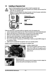
... graphics card is fully seated in the slot. 3. Carefully read the manual that supports your operating system. GA-EP35-DS3R/DS3 Motherboard - 18 - Secure the card's metal bracket to install an expansion card: • Make sure the motherboard supports the expansion card. Install the driver provided with the slot, and press down on your expansion...
... graphics card is fully seated in the slot. 3. Carefully read the manual that supports your operating system. GA-EP35-DS3R/DS3 Motherboard - 18 - Secure the card's metal bracket to install an expansion card: • Make sure the motherboard supports the expansion card. Install the driver provided with the slot, and press down on your expansion...
Manual
Page 19
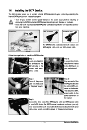
... power cable securely into to the power connector on the bracket. For SATA device in external enclosure, you to connect external SATA device(s) to your motherboard. Before connecting the SATA signal cable, make sure to connect the SATA signal cable. Step 2: Connect the SATA cable from the bracket SATA signal cable...
... power cable securely into to the power connector on the bracket. For SATA device in external enclosure, you to connect external SATA device(s) to your motherboard. Before connecting the SATA signal cable, make sure to connect the SATA signal cable. Step 2: Connect the SATA cable from the bracket SATA signal cable...
Manual
Page 20
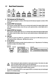
... system provides an optical digital audio in connector. Optical S/PDIF Out Connector This connector provides digital audio out to connect a PS/2 keyboard. GA-EP35-DS3R/DS3 Motherboard - 20 - Coaxial S/PDIF Out Connector This connector provides digital audio out to 1 Gbps data rate. Before using this port for USB ...not rock it side to side to a back panel connector, first remove the cable from your device and then remove it from the motherboard. • When removing the cable, pull it straight out from the connector. RJ-45 LAN Port The Gigabit Ethernet LAN port provides ...
... system provides an optical digital audio in connector. Optical S/PDIF Out Connector This connector provides digital audio out to connect a PS/2 keyboard. GA-EP35-DS3R/DS3 Motherboard - 20 - Coaxial S/PDIF Out Connector This connector provides digital audio out to 1 Gbps data rate. Before using this port for USB ...not rock it side to side to a back panel connector, first remove the cable from your device and then remove it from the motherboard. • When removing the cable, pull it straight out from the connector. RJ-45 LAN Port The Gigabit Ethernet LAN port provides ...
Manual
Page 22
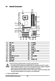
... your devices are compliant with the connectors you wish to connect. • Before installing the devices, be sure to the connector on the motherboard. Only for GA-EP35-DS3R. GA-EP35-DS3R/DS3 Motherboard - 22 - Unplug the power cord from the power outlet to prevent damage to the devices. • After installing the device and before connecting...
... your devices are compliant with the connectors you wish to connect. • Before installing the devices, be sure to the connector on the motherboard. Only for GA-EP35-DS3R. GA-EP35-DS3R/DS3 Motherboard - 22 - Unplug the power cord from the power outlet to prevent damage to the devices. • After installing the device and before connecting...
Manual
Page 23
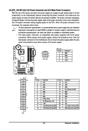
... power supply cable into pins under the protective cover when using a 2x12 power supply, remove the protective cover from the main power connector on the motherboard. The power connector possesses a foolproof design. When using a 2x10 power supply. 3 4 1 2 ATX_12V ATX_12V : Pin No. 1 2 3 4 Definition GND GND +12V +12V 12 24 1 13 ATX ATX..., the power supply can lead to an unstable or unbootable system. • The main power connector is turned off and all the components on the motherboard.
... power supply cable into pins under the protective cover when using a 2x12 power supply, remove the protective cover from the main power connector on the motherboard. The power connector possesses a foolproof design. When using a 2x10 power supply. 3 4 1 2 ATX_12V ATX_12V : Pin No. 1 2 3 4 Definition GND GND +12V +12V 12 24 1 13 ATX ATX..., the power supply can lead to an unstable or unbootable system. • The main power connector is turned off and all the components on the motherboard.
Manual
Page 24
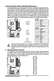
... CPU fan speed control, which requires the use of different color. 34 33 GA-EP35-DS3R/DS3 Motherboard 2 1 - 24 - CPU_FAN: Pin No. Do not place a jumper cap on the headers. 7) FDD (Floppy Disk Drive Connector) This connector is typically designated by a ... fan headers to connect a floppy disk drive. The types of the connector and the floppy disk drive cable. 3/4/5/6) CPU_FAN/SYS_FAN1/SYS_FAN2/PWR_FAN (Fan Headers) The motherboard has a 4-pin CPU fan header (CPU_FAN), a 3-pin system fan header (SYS_FAN1), a 4-pin system fan header (SYS_FAN2) and a 3-pin power fan header (PWR_FAN). ...
... CPU fan speed control, which requires the use of different color. 34 33 GA-EP35-DS3R/DS3 Motherboard 2 1 - 24 - CPU_FAN: Pin No. Do not place a jumper cap on the headers. 7) FDD (Floppy Disk Drive Connector) This connector is typically designated by a ... fan headers to connect a floppy disk drive. The types of the connector and the floppy disk drive cable. 3/4/5/6) CPU_FAN/SYS_FAN1/SYS_FAN2/PWR_FAN (Fan Headers) The motherboard has a 4-pin CPU fan header (CPU_FAN), a 3-pin system fan header (SYS_FAN1), a 4-pin system fan header (SYS_FAN2) and a 3-pin power fan header (PWR_FAN). ...


