Manual
Page 1
GA-EP35-DS3R/ GA-EP35-DS3 LGA775 socket motherboard for Intel® CoreTM processor family/ Intel® Pentium® processor family/Intel® Celeron® processor family User's Manual Rev. 2101 12ME-EP35DS3R-2101R
GA-EP35-DS3R/ GA-EP35-DS3 LGA775 socket motherboard for Intel® CoreTM processor family/ Intel® Pentium® processor family/Intel® Celeron® processor family User's Manual Rev. 2101 12ME-EP35DS3R-2101R
Manual
Page 2
Motherboard GA-EP35-DS3R/DS3 Dec. 21, 2007 Motherboard GA-EP35-DS3R/DS3 Dec. 21, 2007
Motherboard GA-EP35-DS3R/DS3 Dec. 21, 2007 Motherboard GA-EP35-DS3R/DS3 Dec. 21, 2007

Manual
Page 4
Table of Contents Box Contents ...6 OptionalItems ...6 GA-EP35-DS3R/DS3 Motherboard Layout 7 Block Diagram ...8 Chapter 1 Hardware Installation 9 1-1 Installation Precautions 9 1-2 Product Specifications 10 1-3 Installing the CPU and CPU Cooler 13 1-3-1 Installing the CPU 13 1-3-2 Installing the CPU ...
Table of Contents Box Contents ...6 OptionalItems ...6 GA-EP35-DS3R/DS3 Motherboard Layout 7 Block Diagram ...8 Chapter 1 Hardware Installation 9 1-1 Installation Precautions 9 1-2 Product Specifications 10 1-3 Installing the CPU and CPU Cooler 13 1-3-1 Installing the CPU 13 1-3-2 Installing the CPU ...
Manual
Page 6
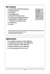
Box Contents GA-EP35-DS3R or GA-EP35-DS3 motherboard Motherboard driver disk User's Manual Quick Installation Guide Intel® LGA775 CPU Installation Guide One IDE cable and one floppy disk drive cable GA-EP35-DS3R: Four SATA 3Gb/s cables GA-EP35-DS3: Two SATA 3Gb/s cables One SATA bracket I/O Shield • The box contents above are subject to change without notice. • The motherboard image...
Box Contents GA-EP35-DS3R or GA-EP35-DS3 motherboard Motherboard driver disk User's Manual Quick Installation Guide Intel® LGA775 CPU Installation Guide One IDE cable and one floppy disk drive cable GA-EP35-DS3R: Four SATA 3Gb/s cables GA-EP35-DS3: Two SATA 3Gb/s cables One SATA bracket I/O Shield • The box contents above are subject to change without notice. • The motherboard image...
Manual
Page 7
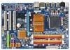
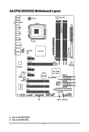
Only for GA-EP35-DS3R. GA-EP35-DS3R/DS3 Motherboard Layout KB_MS RCA_SPDIF R_USB1 R_USB2 R_USB3 ATX_12V LGA775 PHASE LED CPU_FAN ATX GA-EP35-DS3R/DS3 DDRII1 USB_LAN F_AUDIO AUDIO SYS_FAN1 PCIE_3 PCIE_16 RTL8111B PCIE_1 SPDIF_O PCIE_2 CODEC PCI1 SPDIF_I PCI2 IT8718 CD_IN PCI3 COMA Intel® P35 FDD DDRII3 DDRII4 DDRII2 PWR_FAN BATTERY Intel® ICH9R Intel® ICH9 SATAII2 CLR_CMOS SATAII3 GSATAII0 GIGABYTE SATA2 GSATAII1 SATAII0 SATAII1 SATAII4 SATAII5 IDE1 F_USB2 F_USB1 M_BIOS CI F_PANEL LPT B_BIOS PWR_LED SYS_FAN2 Only for GA-EP35-DS3. - 7 -
Only for GA-EP35-DS3R. GA-EP35-DS3R/DS3 Motherboard Layout KB_MS RCA_SPDIF R_USB1 R_USB2 R_USB3 ATX_12V LGA775 PHASE LED CPU_FAN ATX GA-EP35-DS3R/DS3 DDRII1 USB_LAN F_AUDIO AUDIO SYS_FAN1 PCIE_3 PCIE_16 RTL8111B PCIE_1 SPDIF_O PCIE_2 CODEC PCI1 SPDIF_I PCI2 IT8718 CD_IN PCI3 COMA Intel® P35 FDD DDRII3 DDRII4 DDRII2 PWR_FAN BATTERY Intel® ICH9R Intel® ICH9 SATAII2 CLR_CMOS SATAII3 GSATAII0 GIGABYTE SATA2 GSATAII1 SATAII0 SATAII1 SATAII4 SATAII5 IDE1 F_USB2 F_USB1 M_BIOS CI F_PANEL LPT B_BIOS PWR_LED SYS_FAN2 Only for GA-EP35-DS3. - 7 -
Manual
Page 10
...RAID 1, RAID 5, and RAID 10 Š GIGABYTE SATA2 chip: - 1 x IDE connector supporting ATA-133/100/66/33 and up to 2 IDE devices - 2 x SATA 3Gb/s connectors (GSATAII0, GSATAII1) supporting up to 2 SATA 3Gb/s devices - GA-EP35-DS3R/DS3 Motherboard - 10 - 1-2 Product Specifications CPU Front ... 4 x SATA 3Gb/s connectors (SATAII0, SATAII1, SATAII4, SATAII5) supporting up to 1 floppy disk drive Only for GA-EP35-DS3R. Support for SATA RAID 0, RAID 1, and JBOD Š iTE IT8718 chip: - 1 x floppy disk drive connector supporting up to 4 SATA 3Gb/s devices(Note 2) - Support for GA-EP35-DS3.
...RAID 1, RAID 5, and RAID 10 Š GIGABYTE SATA2 chip: - 1 x IDE connector supporting ATA-133/100/66/33 and up to 2 IDE devices - 2 x SATA 3Gb/s connectors (GSATAII0, GSATAII1) supporting up to 2 SATA 3Gb/s devices - GA-EP35-DS3R/DS3 Motherboard - 10 - 1-2 Product Specifications CPU Front ... 4 x SATA 3Gb/s connectors (SATAII0, SATAII1, SATAII4, SATAII5) supporting up to 1 floppy disk drive Only for GA-EP35-DS3R. Support for SATA RAID 0, RAID 1, and JBOD Š iTE IT8718 chip: - 1 x floppy disk drive connector supporting up to 4 SATA 3Gb/s devices(Note 2) - Support for GA-EP35-DS3.
Manual
Page 12
... memory is supported in Windows Vista only) and configure the SATA connectors for the SATA connectors (SATAII0, SATAII1, SATAII4, SATAII5) controlled by motherboard model. (Note 5) Due to Chapter 2, "BIOS Setup," "Integrated Peripherals," for details on enabling AHCI.) (Note 3) Whether the CPU... than 4 GB. (Note 2) To enable hot plug capability for AHCI mode. GA-EP35-DS3R/DS3 Motherboard - 12 - The requirements above do not apply to the SATA connectors (GSATAII0, GSATAII1) controlled by the GIGABYTE SATA2 controller. (Refer to chipset limitation, Intel ICH9R RAID driver does not support...
... memory is supported in Windows Vista only) and configure the SATA connectors for the SATA connectors (SATAII0, SATAII1, SATAII4, SATAII5) controlled by motherboard model. (Note 5) Due to Chapter 2, "BIOS Setup," "Integrated Peripherals," for details on enabling AHCI.) (Note 3) Whether the CPU... than 4 GB. (Note 2) To enable hot plug capability for AHCI mode. GA-EP35-DS3R/DS3 Motherboard - 12 - The requirements above do not apply to the SATA connectors (GSATAII0, GSATAII1) controlled by the GIGABYTE SATA2 controller. (Refer to chipset limitation, Intel ICH9R RAID driver does not support...

Manual
Page 14
Step 4: Hold the CPU with the socket alignment keys) and gently insert the CPU into the motherboard CPU socket. Step 2: Remove the protective socket cover. GA-EP35-DS3R/DS3 Motherboard - 14 - Align the CPU pin one marking (triangle) with the pin one corner of the CPU socket (or you may align the CPU notches with ...
Step 4: Hold the CPU with the socket alignment keys) and gently insert the CPU into the motherboard CPU socket. Step 2: Remove the protective socket cover. GA-EP35-DS3R/DS3 Motherboard - 14 - Align the CPU pin one marking (triangle) with the pin one corner of the CPU socket (or you may align the CPU notches with ...
Manual
Page 16
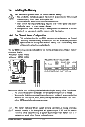
... bandwidth. Four Modules DS/SS DS/SS DS/SS DDRII4 - If you begin to install the memory: • Make sure that the motherboard supports the memory. DS/SS DS/SS (SS=Single-Sided, DS=Double-Sided, "- -"=No Memory) DDRII1 DDRII2 DDRII3 DDRII4 Due to ... capacity, brand, speed, and chips be populated and remain in Dual Channel mode. 1. A memory module can be used . (Go to GIGABYTE's website for optimum performance. GA-EP35-DS3R/DS3 Motherboard - 16 - It is installed. 2. DS/SS - - 1-4 Installing the Memory Read the following guidelines before you are unable to insert ...
... bandwidth. Four Modules DS/SS DS/SS DS/SS DDRII4 - If you begin to install the memory: • Make sure that the motherboard supports the memory. DS/SS DS/SS (SS=Single-Sided, DS=Double-Sided, "- -"=No Memory) DDRII1 DDRII2 DDRII3 DDRII4 Due to ... capacity, brand, speed, and chips be populated and remain in Dual Channel mode. 1. A memory module can be used . (Go to GIGABYTE's website for optimum performance. GA-EP35-DS3R/DS3 Motherboard - 16 - It is installed. 2. DS/SS - - 1-4 Installing the Memory Read the following guidelines before you are unable to insert ...
Manual
Page 18
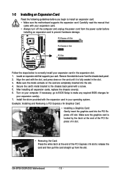
...and then pull the card straight up from the slot. If necessary, go to BIOS Setup to correctly install your expansion card(s). 7. GA-EP35-DS3R/DS3 Motherboard - 18 - PCI Express x16 Slot PCI Express x1 Slot PCI Slot Follow the steps below to make any required BIOS changes for ...1-5 Installing an Expansion Card Read the following guidelines before installing an expansion card to install an expansion card: • Make sure the motherboard supports the expansion card. Carefully read the manual that supports your expansion card. • Always turn off the computer and unplug the power...
...and then pull the card straight up from the slot. If necessary, go to BIOS Setup to correctly install your expansion card(s). 7. GA-EP35-DS3R/DS3 Motherboard - 18 - PCI Express x16 Slot PCI Express x1 Slot PCI Slot Follow the steps below to make any required BIOS changes for ...1-5 Installing an Expansion Card Read the following guidelines before installing an expansion card to install an expansion card: • Make sure the motherboard supports the expansion card. Carefully read the manual that supports your expansion card. • Always turn off the computer and unplug the power...
Manual
Page 20
...to an external audio system that your audio system provides a coaxial digital audio in connector. Before using this feature, ensure that supports digital coaxial audio. GA-EP35-DS3R/DS3 Motherboard - 20 - Do not rock it side to side to an external audio system that your device and then remove it from the... motherboard. • When removing the cable, pull it straight out from your audio system provides an optical digital audio in connector. Before using this port ...
...to an external audio system that your audio system provides a coaxial digital audio in connector. Before using this feature, ensure that supports digital coaxial audio. GA-EP35-DS3R/DS3 Motherboard - 20 - Do not rock it side to side to an external audio system that your device and then remove it from the... motherboard. • When removing the cable, pull it straight out from your audio system provides an optical digital audio in connector. Before using this port ...
Manual
Page 22
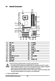
...) SPDIF_O 18) F_USB1/F_USB2 19) COMA 20) LPT 21) CLR_CMOS 22) CI 23) PHASE LED Read the following guidelines before turning on the motherboard. GA-EP35-DS3R/DS3 Motherboard - 22 - Only for GA-EP35-DS3R. Unplug the power cord from the power outlet to prevent damage to the devices. • After installing the device and before connecting external devices...
...) SPDIF_O 18) F_USB1/F_USB2 19) COMA 20) LPT 21) CLR_CMOS 22) CI 23) PHASE LED Read the following guidelines before turning on the motherboard. GA-EP35-DS3R/DS3 Motherboard - 22 - Only for GA-EP35-DS3R. Unplug the power cord from the power outlet to prevent damage to the devices. • After installing the device and before connecting external devices...
Manual
Page 24
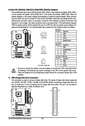
When connecting a fan cable, be sure to connect it is typically designated by a stripe of different color. 34 33 GA-EP35-DS3R/DS3 Motherboard 2 1 - 24 - The black connector wire is used to locate pin 1 of a CPU fan with colorcoded power connector wires. Definition 1...Speed Control 1 SYS_FAN2 SYS_FAN2: Pin No. 1 2 3 4 Definition GND Speed Control Sense +5V 1 SYS_FAN1 / PWR_FAN SYS_FAN1 / PWR_FAN : Pin No. The motherboard supports CPU fan speed control, which requires the use of the connector and the floppy disk drive cable. For optimum heat dissipation, it in damage...
When connecting a fan cable, be sure to connect it is typically designated by a stripe of different color. 34 33 GA-EP35-DS3R/DS3 Motherboard 2 1 - 24 - The black connector wire is used to locate pin 1 of a CPU fan with colorcoded power connector wires. Definition 1...Speed Control 1 SYS_FAN2 SYS_FAN2: Pin No. 1 2 3 4 Definition GND Speed Control Sense +5V 1 SYS_FAN1 / PWR_FAN SYS_FAN1 / PWR_FAN : Pin No. The motherboard supports CPU fan speed control, which requires the use of the connector and the floppy disk drive cable. For optimum heat dissipation, it in damage...
Manual
Page 26
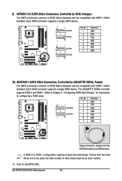
...A RAID 0 or RAID 1 configuration requires at least two hard drives. 9) SATAII0/1/4/5 (SATA 3Gb/s Connectors, Controlled by GIGABYTE SATA2, Purple) The SATA connectors conform to SATA 3Gb/s standard and are compatible with SATA 1.5Gb/s standard. Pin No. GA-EP35-DS3R/DS3 Motherboard - 26 - Definition 1 GND 7 1 2 TXP GSATAII0 3 TXN GSATAII1 4 GND 5 RXN 1 7 6 RXP ... (SATA 3Gb/s Connectors, Controlled by ICH9, Orange) The SATA connectors conform to Chapter 5, "Configuring SATA Hard Drive(s)," for GA-EP35-DS3. The GIGABYTE SATA2 controller supports RAID 0 and RAID 1.
...A RAID 0 or RAID 1 configuration requires at least two hard drives. 9) SATAII0/1/4/5 (SATA 3Gb/s Connectors, Controlled by GIGABYTE SATA2, Purple) The SATA connectors conform to SATA 3Gb/s standard and are compatible with SATA 1.5Gb/s standard. Pin No. GA-EP35-DS3R/DS3 Motherboard - 26 - Definition 1 GND 7 1 2 TXP GSATAII0 3 TXN GSATAII1 4 GND 5 RXN 1 7 6 RXP ... (SATA 3Gb/s Connectors, Controlled by ICH9, Orange) The SATA connectors conform to Chapter 5, "Configuring SATA Hard Drive(s)," for GA-EP35-DS3. The GIGABYTE SATA2 controller supports RAID 0 and RAID 1.

Manual
Page 28
...): Connects to the pin assignments below. A front panel module mainly consists of power switch, reset switch, power LED, hard drive activity LED, speaker and etc. GA-EP35-DS3R/DS3 Motherboard - 28 - RESRES+ NC Hard Drive Reset Activity LED Switch • MSG (Message/Power/Sleep LED, Yellow): System Status LED Connects to perform a normal restart. •...
...): Connects to the pin assignments below. A front panel module mainly consists of power switch, reset switch, power LED, hard drive activity LED, speaker and etc. GA-EP35-DS3R/DS3 Motherboard - 28 - RESRES+ NC Hard Drive Reset Activity LED Switch • MSG (Message/Power/Sleep LED, Yellow): System Status LED Connects to perform a normal restart. •...
Manual
Page 30
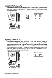
... require you wish to connect an HDMI display to the graphics card and have digital audio output from your motherboard to certain expansion cards like graphics cards and sound cards. Definition 1 SPDIFO 2 GND GA-EP35-DS3R/DS3 Motherboard - 30 - Definition 1 Power 2 SPDIFI 3 GND 17) SPDIF_O (S/PDIF Out Header) This header supports digital S/PDIF out...cable, carefully read the manual for your graphics card if you to use a S/PDIF digital audio cable for digital audio output from your motherboard to your expansion card. 1 Pin No. For purchasing the optional S/PDIF in cable.
... require you wish to connect an HDMI display to the graphics card and have digital audio output from your motherboard to certain expansion cards like graphics cards and sound cards. Definition 1 SPDIFO 2 GND GA-EP35-DS3R/DS3 Motherboard - 30 - Definition 1 Power 2 SPDIFI 3 GND 17) SPDIF_O (S/PDIF Out Header) This header supports digital S/PDIF out...cable, carefully read the manual for your graphics card if you to use a S/PDIF digital audio cable for digital audio output from your motherboard to your expansion card. 1 Pin No. For purchasing the optional S/PDIF in cable.

Manual
Page 32
... an optional LPT port cable. To clear the CMOS values, place a jumper cap on your computer and unplug the power cord from the jumper. GA-EP35-DS3R/DS3 Motherboard - 32 - Open: Normal Short: Clear CMOS Values • Always turn off your computer, be sure to remove the jumper cap from the ... the two pins or use a metal object like a screwdriver to clear the CMOS values (e.g. Failure to do so may cause damage to the motherboard. • After system restart, go to BIOS Setup to load factory defaults (select Load Optimized Defaults) or manually configure the BIOS settings (refer...
... an optional LPT port cable. To clear the CMOS values, place a jumper cap on your computer and unplug the power cord from the jumper. GA-EP35-DS3R/DS3 Motherboard - 32 - Open: Normal Short: Clear CMOS Values • Always turn off your computer, be sure to remove the jumper cap from the ... the two pins or use a metal object like a screwdriver to clear the CMOS values (e.g. Failure to do so may cause damage to the motherboard. • After system restart, go to BIOS Setup to load factory defaults (select Load Optimized Defaults) or manually configure the BIOS settings (refer...
Manual
Page 34
GA-EP35-DS3R/DS3 Motherboard - 34 -
GA-EP35-DS3R/DS3 Motherboard - 34 -

Manual
Page 36
... enter BIOS Setup. : Xpress Recovery2 If you to set the first boot device without having to access the Q-Flash utility directly without entering BIOS Setup. EP35-DS3R F1b . . . . : BIOS Setup : XpressRecovery2 : Boot Menu : Qflash 12/04/2007-P35-ICH9-6A89OG0NC-00 Function Keys Function Keys: :...POST. 2-1 Startup Screen The following screens may appear when the computer boots. The system will still be used for one time only. GA-EP35-DS3R/DS3 Motherboard - 36 - After system restart, the device boot order will directly boot from the device configured in Boot Menu is effective for ...
... enter BIOS Setup. : Xpress Recovery2 If you to set the first boot device without having to access the Q-Flash utility directly without entering BIOS Setup. EP35-DS3R F1b . . . . : BIOS Setup : XpressRecovery2 : Boot Menu : Qflash 12/04/2007-P35-ICH9-6A89OG0NC-00 Function Keys Function Keys: :...POST. 2-1 Startup Screen The following screens may appear when the computer boots. The system will still be used for one time only. GA-EP35-DS3R/DS3 Motherboard - 36 - After system restart, the device boot order will directly boot from the device configured in Boot Menu is effective for ...

Manual
Page 77
...Chapter 1," "Hardware Installation," to identify the SATA controller for GA-EP35-DS3R. (Note 1) Skip this step if you do not want to create RAID array on the motherboard. Only for the SATA port. (For example, on the GA-EP35-DS3R motherboard, the SATAII0, SATAII1, SATAII2, SATAII3, SATAII4 and SATAII5 ... than one hard drive. • An empty formatted floppy disk. • Windows Vista/XP/2000 (Note 3) setup disk. • Motherboard driver disk. 5-1-1 Configuring Intel® ICH9R SATA Controllers A. Install SATA hard drive(s) in your computer. Configure a RAID array in BIOS Setup...
...Chapter 1," "Hardware Installation," to identify the SATA controller for GA-EP35-DS3R. (Note 1) Skip this step if you do not want to create RAID array on the motherboard. Only for the SATA port. (For example, on the GA-EP35-DS3R motherboard, the SATAII0, SATAII1, SATAII2, SATAII3, SATAII4 and SATAII5 ... than one hard drive. • An empty formatted floppy disk. • Windows Vista/XP/2000 (Note 3) setup disk. • Motherboard driver disk. 5-1-1 Configuring Intel® ICH9R SATA Controllers A. Install SATA hard drive(s) in your computer. Configure a RAID array in BIOS Setup...


