Manual
Page 1
GA-EP35-DS3R/ GA-EP35-DS3 LGA775 socket motherboard for Intel® CoreTM processor family/ Intel® Pentium® processor family/Intel® Celeron® processor family User's Manual Rev. 2101 12ME-EP35DS3R-2101R
GA-EP35-DS3R/ GA-EP35-DS3 LGA775 socket motherboard for Intel® CoreTM processor family/ Intel® Pentium® processor family/Intel® Celeron® processor family User's Manual Rev. 2101 12ME-EP35DS3R-2101R
Manual
Page 2
Motherboard GA-EP35-DS3R/DS3 Dec. 21, 2007 Motherboard GA-EP35-DS3R/DS3 Dec. 21, 2007
Motherboard GA-EP35-DS3R/DS3 Dec. 21, 2007 Motherboard GA-EP35-DS3R/DS3 Dec. 21, 2007
Manual
Page 3
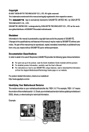
... product-related information, check on our website at: http://www.gigabyte.com.tw Identifying Your Motherboard Revision The revision number on your motherboard revision before updating motherboard BIOS, drivers, or when looking for technical information. For example, "REV: 1.0" means the revision of the motherboard is designated by GIGA-BYTE TECHNOLOGY CO., LTD as the exclu...
... product-related information, check on our website at: http://www.gigabyte.com.tw Identifying Your Motherboard Revision The revision number on your motherboard revision before updating motherboard BIOS, drivers, or when looking for technical information. For example, "REV: 1.0" means the revision of the motherboard is designated by GIGA-BYTE TECHNOLOGY CO., LTD as the exclu...

Manual
Page 4
Table of Contents Box Contents ...6 OptionalItems ...6 GA-EP35-DS3R/DS3 Motherboard Layout 7 Block Diagram ...8 Chapter 1 Hardware Installation 9 1-1 Installation Precautions 9 1-2 Product Specifications 10 1-3 Installing the CPU and CPU Cooler 13 1-3-1 Installing the CPU 13 1-3-2 Installing the CPU ...
Table of Contents Box Contents ...6 OptionalItems ...6 GA-EP35-DS3R/DS3 Motherboard Layout 7 Block Diagram ...8 Chapter 1 Hardware Installation 9 1-1 Installation Precautions 9 1-2 Product Specifications 10 1-3 Installing the CPU and CPU Cooler 13 1-3-1 Installing the CPU 13 1-3-2 Installing the CPU ...
Manual
Page 6
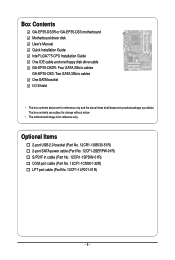
...-1SPDIN-01R) COM port cable (Part No. 12CF1-1CM001-32R) LPT port cable (Part No. 12CF1-1LP001-01R) - 6 - Box Contents GA-EP35-DS3R or GA-EP35-DS3 motherboard Motherboard driver disk User's Manual Quick Installation Guide Intel® LGA775 CPU Installation Guide One IDE cable and one floppy disk drive cable... GA-EP35-DS3R: Four SATA 3Gb/s cables GA-EP35-DS3: Two SATA 3Gb/s cables One SATA bracket I/O Shield • The box contents above are subject to change without notice. • The motherboard image is for reference only and the actual items...
...-1SPDIN-01R) COM port cable (Part No. 12CF1-1CM001-32R) LPT port cable (Part No. 12CF1-1LP001-01R) - 6 - Box Contents GA-EP35-DS3R or GA-EP35-DS3 motherboard Motherboard driver disk User's Manual Quick Installation Guide Intel® LGA775 CPU Installation Guide One IDE cable and one floppy disk drive cable... GA-EP35-DS3R: Four SATA 3Gb/s cables GA-EP35-DS3: Two SATA 3Gb/s cables One SATA bracket I/O Shield • The box contents above are subject to change without notice. • The motherboard image is for reference only and the actual items...
Manual
Page 7
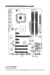
GA-EP35-DS3R/DS3 Motherboard Layout KB_MS RCA_SPDIF R_USB1 R_USB2 R_USB3 ATX_12V LGA775 PHASE LED CPU_FAN ATX GA-EP35-DS3R/DS3 DDRII1 USB_LAN F_AUDIO AUDIO SYS_FAN1 PCIE_3 PCIE_16 RTL8111B PCIE_1 SPDIF_O PCIE_2 CODEC PCI1 SPDIF_I PCI2 IT8718 CD_IN PCI3 COMA Intel® P35 FDD DDRII3 DDRII4 DDRII2 PWR_FAN BATTERY Intel® ICH9R Intel® ICH9 SATAII2 CLR_CMOS SATAII3 GSATAII0 GIGABYTE SATA2 GSATAII1 SATAII0 SATAII1 SATAII4 SATAII5 IDE1 F_USB2 F_USB1 M_BIOS CI F_PANEL LPT B_BIOS PWR_LED SYS_FAN2 Only for GA-EP35-DS3. - 7 - Only for GA-EP35-DS3R.
GA-EP35-DS3R/DS3 Motherboard Layout KB_MS RCA_SPDIF R_USB1 R_USB2 R_USB3 ATX_12V LGA775 PHASE LED CPU_FAN ATX GA-EP35-DS3R/DS3 DDRII1 USB_LAN F_AUDIO AUDIO SYS_FAN1 PCIE_3 PCIE_16 RTL8111B PCIE_1 SPDIF_O PCIE_2 CODEC PCI1 SPDIF_I PCI2 IT8718 CD_IN PCI3 COMA Intel® P35 FDD DDRII3 DDRII4 DDRII2 PWR_FAN BATTERY Intel® ICH9R Intel® ICH9 SATAII2 CLR_CMOS SATAII3 GSATAII0 GIGABYTE SATA2 GSATAII1 SATAII0 SATAII1 SATAII4 SATAII5 IDE1 F_USB2 F_USB1 M_BIOS CI F_PANEL LPT B_BIOS PWR_LED SYS_FAN2 Only for GA-EP35-DS3. - 7 - Only for GA-EP35-DS3R.

Manual
Page 9
...to the internal connectors on the computer power during the installation process can become damaged as a motherboard, CPU or memory. Chapter 1 Hardware Installation 1-1 Installation Precautions The motherboard contains numerous delicate electronic circuits and components which can lead to damage to system components as well...as physical harm to the user. • If you do not remove or break motherboard S/N (Serial Number) sticker or warranty sticker provided by unplugging the power cord from the motherboard, make sure the power supply has been turned off. • Before turning on the...
...to the internal connectors on the computer power during the installation process can become damaged as a motherboard, CPU or memory. Chapter 1 Hardware Installation 1-1 Installation Precautions The motherboard contains numerous delicate electronic circuits and components which can lead to damage to system components as well...as physical harm to the user. • If you do not remove or break motherboard S/N (Serial Number) sticker or warranty sticker provided by unplugging the power cord from the motherboard, make sure the power supply has been turned off. • Before turning on the...
Manual
Page 10
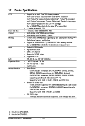
Support for GA-EP35-DS3. Only for SATA RAID 0, RAID 1, RAID 5, and RAID 10 Š GIGABYTE SATA2 chip: - 1 x IDE connector supporting ATA-133/100/66/33 and up to 2 IDE devices - 2 x SATA 3Gb/s connectors (GSATAII0, GSATAII1) supporting up to 2 SATA 3Gb/s devices - GA-EP35-DS3R/DS3 Motherboard - 10 - 1-2...(O.C.)/1066/800/667 MHz memory modules (Go to GIGABYTE's website for the latest memory support list.) Š Realtek ALC889A codec Š High Definition Audio Š 2/4/5.1/7.1-channel Š Support for S/PDIF In/Out Š Support for GA-EP35-DS3R. Support for SATA RAID 0, RAID 1, ...
Support for GA-EP35-DS3. Only for SATA RAID 0, RAID 1, RAID 5, and RAID 10 Š GIGABYTE SATA2 chip: - 1 x IDE connector supporting ATA-133/100/66/33 and up to 2 IDE devices - 2 x SATA 3Gb/s connectors (GSATAII0, GSATAII1) supporting up to 2 SATA 3Gb/s devices - GA-EP35-DS3R/DS3 Motherboard - 10 - 1-2...(O.C.)/1066/800/667 MHz memory modules (Go to GIGABYTE's website for the latest memory support list.) Š Realtek ALC889A codec Š High Definition Audio Š 2/4/5.1/7.1-channel Š Support for S/PDIF In/Out Š Support for GA-EP35-DS3R. Support for SATA RAID 0, RAID 1, ...
Manual
Page 12
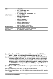
The requirements above do not apply to the SATA connectors (GSATAII0, GSATAII1) controlled by the GIGABYTE SATA2 controller. (Refer to Chapter 2, "BIOS Setup," "Integrated Peripherals," for details on enabling AHCI.) (Note 3) Whether the CPU fan speed control function is...you must install Windows Vista (on ICH9, hot plug is supported will be less than 4 GB. (Note 2) To enable hot plug capability for AHCI mode. GA-EP35-DS3R/DS3 Motherboard - 12 - BIOS Unique Features Bundled Software Operating System Form Factor Š 2 x 8 Mbit flash Š Use of physical memory is installed, the actual ...
The requirements above do not apply to the SATA connectors (GSATAII0, GSATAII1) controlled by the GIGABYTE SATA2 controller. (Refer to Chapter 2, "BIOS Setup," "Integrated Peripherals," for details on enabling AHCI.) (Note 3) Whether the CPU fan speed control function is...you must install Windows Vista (on ICH9, hot plug is supported will be less than 4 GB. (Note 2) To enable hot plug capability for AHCI mode. GA-EP35-DS3R/DS3 Motherboard - 12 - BIOS Unique Features Bundled Software Operating System Form Factor Š 2 x 8 Mbit flash Š Use of physical memory is installed, the actual ...
Manual
Page 13
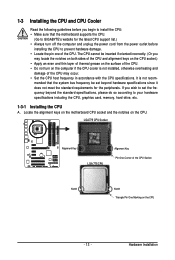
... it does not meet the standard requirements for the latest CPU support list.) • Always turn on the CPU. Locate the alignment keys on the motherboard CPU socket and the notches on the computer if the CPU cooler is not recom- LGA775 CPU Socket Alignment Key LGA 775 CPU Alignment Key... Pin One Corner of the CPU Socket Notch Notch Triangle Pin One Marking on the CPU - 13 - mended that the motherboard supports the CPU. (Go to GIGABYTE's website for the peripherals. Hardware Installation
... it does not meet the standard requirements for the latest CPU support list.) • Always turn on the CPU. Locate the alignment keys on the motherboard CPU socket and the notches on the computer if the CPU cooler is not recom- LGA775 CPU Socket Alignment Key LGA 775 CPU Alignment Key... Pin One Corner of the CPU Socket Notch Notch Triangle Pin One Marking on the CPU - 13 - mended that the motherboard supports the CPU. (Go to GIGABYTE's website for the peripherals. Hardware Installation

Manual
Page 14
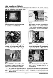
... marking (triangle) with the pin one corner of the CPU socket (or you may align the CPU notches with your thumb and index fingers. GA-EP35-DS3R/DS3 Motherboard - 14 - B. Before installing the CPU, make sure to turn off the computer and unplug the power cord from the power outlet to prevent... damage to correctly install the CPU into the motherboard CPU socket. Follow the steps below to the CPU. Step 4: Hold the CPU with the socket alignment ...
... marking (triangle) with the pin one corner of the CPU socket (or you may align the CPU notches with your thumb and index fingers. GA-EP35-DS3R/DS3 Motherboard - 14 - B. Before installing the CPU, make sure to turn off the computer and unplug the power cord from the power outlet to prevent... damage to correctly install the CPU into the motherboard CPU socket. Follow the steps below to the CPU. Step 4: Hold the CPU with the socket alignment ...
Manual
Page 15
... contrary, is to install.) Step 3: Place the cooler atop the CPU, aligning the four push pins through the pin holes on the motherboard. Push down each push pin. Inadequately removing the CPU cooler may adhere to your CPU cooler installation manual for instructions on the push pins... damage the CPU. - 15 - Hardware Installation 1-3-2 Installing the CPU Cooler Follow the steps below to correctly install the CPU cooler on the motherboard. (The following procedure uses Intel® boxed cooler as the picture above, the installation is complete. Check that the Male and Female push ...
... contrary, is to install.) Step 3: Place the cooler atop the CPU, aligning the four push pins through the pin holes on the motherboard. Push down each push pin. Inadequately removing the CPU cooler may adhere to your CPU cooler installation manual for instructions on the push pins... damage the CPU. - 15 - Hardware Installation 1-3-2 Installing the CPU Cooler Follow the steps below to correctly install the CPU cooler on the motherboard. (The following procedure uses Intel® boxed cooler as the picture above, the installation is complete. Check that the Male and Female push ...
Manual
Page 16
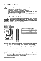
... four DDR2 memory sockets are unable to insert the memory, switch the direction. 1-4-1 Dual Channel Memory Configuration This motherboard provides four DDR2 memory sockets and supports Dual Channel Technology. Dual Channel mode cannot be used and installed in Dual...No Memory) DDRII1 DDRII2 DDRII3 DDRII4 Due to chipset limitation, read the following guidelines before installing the memory to GIGABYTE's website for optimum performance. GA-EP35-DS3R/DS3 Motherboard - 16 - It is operating in Flex Memory Mode will automatically detect the specifications and capacity of the ...
... four DDR2 memory sockets are unable to insert the memory, switch the direction. 1-4-1 Dual Channel Memory Configuration This motherboard provides four DDR2 memory sockets and supports Dual Channel Technology. Dual Channel mode cannot be used and installed in Dual...No Memory) DDRII1 DDRII2 DDRII3 DDRII4 Due to chipset limitation, read the following guidelines before installing the memory to GIGABYTE's website for optimum performance. GA-EP35-DS3R/DS3 Motherboard - 16 - It is operating in Flex Memory Mode will automatically detect the specifications and capacity of the ...

Manual
Page 17
... , make sure to turn off the computer and unplug the power cord from the power outlet to prevent damage to install DDR2 DIMMs on this motherboard. Place the memory module on the socket. Step 1: Note the orientation of the memory socket.
... , make sure to turn off the computer and unplug the power cord from the power outlet to prevent damage to install DDR2 DIMMs on this motherboard. Place the memory module on the socket. Step 1: Note the orientation of the memory socket.
Manual
Page 18
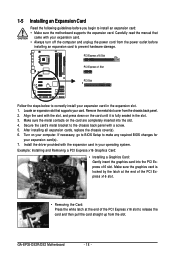
Turn on your expansion card(s). 7. If necessary, go to BIOS Setup to make any required BIOS changes for your computer. GA-EP35-DS3R/DS3 Motherboard - 18 - After installing all expansion cards, replace the chassis cover(s). 6. 1-5 Installing an Expansion Card Read the following guidelines before installing...with your expansion card in the slot. 3. Secure the card's metal bracket to install an expansion card: • Make sure the motherboard supports the expansion card. Install the driver provided with the slot, and press down on the card are completely inserted into the PCI ...
Turn on your expansion card(s). 7. If necessary, go to BIOS Setup to make any required BIOS changes for your computer. GA-EP35-DS3R/DS3 Motherboard - 18 - After installing all expansion cards, replace the chassis cover(s). 6. 1-5 Installing an Expansion Card Read the following guidelines before installing...with your expansion card in the slot. 3. Secure the card's metal bracket to install an expansion card: • Make sure the motherboard supports the expansion card. Install the driver provided with the slot, and press down on the card are completely inserted into the PCI ...
Manual
Page 19
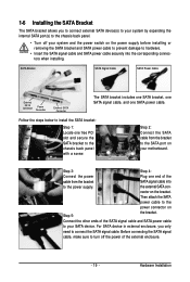
... off the power of the external enclosure. - 19 - nector on Step 5: the bracket. Before connecting the SATA signal cable, make sure to turn off your motherboard. 1-6 Installing the SATA Bracket The SATA bracket allows you only need to connect the SATA signal cable. Follow the steps below to your SATA device...
... off the power of the external enclosure. - 19 - nector on Step 5: the bracket. Before connecting the SATA signal cable, make sure to turn off your motherboard. 1-6 Installing the SATA Bracket The SATA bracket allows you only need to connect the SATA signal cable. Follow the steps below to your SATA device...
Manual
Page 20
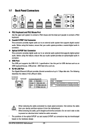
... No data transmission or receiving is occurring • When removing the cable connected to an external audio system that supports digital optical audio. GA-EP35-DS3R/DS3 Motherboard - 20 - Use this feature, ensure that your audio system provides an optical digital audio in connector. Coaxial S/PDIF Out Connector This...the lower port (purple) to 1 Gbps data rate. Before using this feature, ensure that your device and then remove it from the motherboard. • When removing the cable, pull it side to side to an external audio system that supports digital coaxial audio.
... No data transmission or receiving is occurring • When removing the cable connected to an external audio system that supports digital optical audio. GA-EP35-DS3R/DS3 Motherboard - 20 - Use this feature, ensure that your audio system provides an optical digital audio in connector. Coaxial S/PDIF Out Connector This...the lower port (purple) to 1 Gbps data rate. Before using this feature, ensure that your device and then remove it from the motherboard. • When removing the cable, pull it side to side to an external audio system that supports digital coaxial audio.
Manual
Page 22
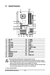
Only for GA-EP35-DS3R. GA-EP35-DS3R/DS3 Motherboard - 22 - 1-8 Internal Connectors 1 3 23 2 7 14 4 5 6 12 21 17 9 16 10 8 15 19 20 18 22 11 13 1) ATX_12V 2) ATX 3) CPU_FAN 4) SYS_FAN1 5) SYS_FAN2 6) PWR_FAN 7) FDD 8) IDE1 9) ..., make sure your devices are compliant with the connectors you wish to connect. • Before installing the devices, be sure to the connector on the motherboard. Unplug the power cord from the power outlet to prevent damage to the devices. • After installing the device and before connecting external devices: •...
Only for GA-EP35-DS3R. GA-EP35-DS3R/DS3 Motherboard - 22 - 1-8 Internal Connectors 1 3 23 2 7 14 4 5 6 12 21 17 9 16 10 8 15 19 20 18 22 11 13 1) ATX_12V 2) ATX 3) CPU_FAN 4) SYS_FAN1 5) SYS_FAN2 6) PWR_FAN 7) FDD 8) IDE1 9) ..., make sure your devices are compliant with the connectors you wish to connect. • Before installing the devices, be sure to the connector on the motherboard. Unplug the power cord from the power outlet to prevent damage to the devices. • After installing the device and before connecting external devices: •...
Manual
Page 23
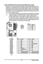
... cable into pins under the protective cover when using a 2x12 power supply, remove the protective cover from the main power connector on the motherboard. The power connector possesses a foolproof design. The 12V power connector mainly supplies power to an unstable or unbootable system. • The ...main power connector is turned off and all the components on the motherboard. Connect the power supply cable to all devices are properly installed. Before connecting the power connector, first make sure the power supply ...
... cable into pins under the protective cover when using a 2x12 power supply, remove the protective cover from the main power connector on the motherboard. The power connector possesses a foolproof design. The 12V power connector mainly supplies power to an unstable or unbootable system. • The ...main power connector is turned off and all the components on the motherboard. Connect the power supply cable to all devices are properly installed. Before connecting the power connector, first make sure the power supply ...
Manual
Page 24
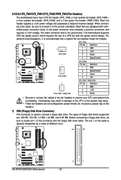
3/4/5/6) CPU_FAN/SYS_FAN1/SYS_FAN2/PWR_FAN (Fan Headers) The motherboard has a 4-pin CPU fan header (CPU_FAN), a 3-pin system fan header (SYS_FAN1), a 4-pin system fan header (SYS_FAN2)... positive connection and requires a +12V voltage. Before connecting a floppy disk drive, be sure to connect a floppy disk drive. The motherboard supports CPU fan speed control, which requires the use of the connector and the floppy disk drive cable. Most fans are : 360... a fan cable, be installed inside the chassis. The types of different color. 34 33 GA-EP35-DS3R/DS3 Motherboard 2 1 - 24 -
3/4/5/6) CPU_FAN/SYS_FAN1/SYS_FAN2/PWR_FAN (Fan Headers) The motherboard has a 4-pin CPU fan header (CPU_FAN), a 3-pin system fan header (SYS_FAN1), a 4-pin system fan header (SYS_FAN2)... positive connection and requires a +12V voltage. Before connecting a floppy disk drive, be sure to connect a floppy disk drive. The motherboard supports CPU fan speed control, which requires the use of the connector and the floppy disk drive cable. Most fans are : 360... a fan cable, be installed inside the chassis. The types of different color. 34 33 GA-EP35-DS3R/DS3 Motherboard 2 1 - 24 -


