
Manual
Page 2
Installing the Smart TPM Utility 4 3. Other Bluetooth Settings 21 4.4. Initializing the TPM chip 5 3.1. Table of Contents TPM Configuration Procedure 3 1. Advanced Mode...8 4. Creating a Bluetooth Cell Phone Key 19 4.3. Configuring the Smart TPM Utility 18 4.1. Other Features...21 - 2 - Initializing the TPM Chip with the Smart TPM Utility 5 3.2. Creating a USB Key 18 4.2. Installing the Infineon TPM Driver and the Smart TPM Utility 4 2.1. Configuring the System BIOS 3 2. Installing the Infineon TPM Driver 4 2.2.
Installing the Smart TPM Utility 4 3. Other Bluetooth Settings 21 4.4. Initializing the TPM chip 5 3.1. Table of Contents TPM Configuration Procedure 3 1. Advanced Mode...8 4. Creating a Bluetooth Cell Phone Key 19 4.3. Configuring the Smart TPM Utility 18 4.1. Other Features...21 - 2 - Initializing the TPM Chip with the Smart TPM Utility 5 3.2. Creating a USB Key 18 4.2. Installing the Infineon TPM Driver and the Smart TPM Utility 4 2.1. Configuring the System BIOS 3 2. Installing the Infineon TPM Driver 4 2.2.

Manual
Page 3
... To enable the TPM, follow the steps below in the BIOS Setup program. - 3 - Installing the Infineon TPM driver and the Smart TPM utility 3. Configuring the System BIOS To use the Clear Security Chip setting (press + in the BIOS main menu to display this setting) to activate the TPM ...chip, set the User Password in sequence: 1. Be sure to save changes and then exit the BIOS Setup program. It's recommended that you use the TPM functionality, first enter the system BIOS Setup to clear the TPM chip. Previously encrypted files will appear. Step 1: As the computer starts...
... To enable the TPM, follow the steps below in the BIOS Setup program. - 3 - Installing the Infineon TPM driver and the Smart TPM utility 3. Configuring the System BIOS To use the Clear Security Chip setting (press + in the BIOS main menu to display this setting) to activate the TPM ...chip, set the User Password in sequence: 1. Be sure to save changes and then exit the BIOS Setup program. It's recommended that you use the TPM functionality, first enter the system BIOS Setup to clear the TPM chip. Previously encrypted files will appear. Step 1: As the computer starts...

Manual
Page 5
... the Infineon Security Platform initialization and its functions. Create Your Smart TPM Key Set your own password. Initializing the TPM chip After configuring the system BIOS and installing the driver software, the Infineon Security Platform icon , which your PSD data when connecting to -use the "Secure e-mail" or "File and folder...
... the Infineon Security Platform initialization and its functions. Create Your Smart TPM Key Set your own password. Initializing the TPM chip After configuring the system BIOS and installing the driver software, the Infineon Security Platform icon , which your PSD data when connecting to -use the "Secure e-mail" or "File and folder...

Manual
Page 6
..., since the file system allocates some space. Initialization Procedure of available letters. Auto Generated Password A password will be no more than 32 characters in the BIOS Setup program. • This password incorporates the functionalities of the "Owner Password," "User Password," "Emergency Recovery Token Password," and "Password Reset Token Password" of the...
..., since the file system allocates some space. Initialization Procedure of available letters. Auto Generated Password A password will be no more than 32 characters in the BIOS Setup program. • This password incorporates the functionalities of the "Owner Password," "User Password," "Emergency Recovery Token Password," and "Password Reset Token Password" of the...

Manual
Page 7
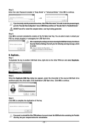
... receiver and turn on the search and Bluetooth functions on your cell phone. Then select the USB flash drive that you plug in the system BIOS. Selecting the Enable Backup to search for pairing with your cell phone for the USB flash drive(s) that you want to that on the left... PSD, and the Smart TPM user key(s). - 7 - Upon completing the steps above, click OK to search for pairing. Enter a passkey (8~16 digits recommended) in the BIOS, the latter will be used for the Bluetooth enabled cell phone(s). Create a USB key: Select the Use USB storage check box and click Refresh to...
... receiver and turn on the search and Bluetooth functions on your cell phone. Then select the USB flash drive that you plug in the system BIOS. Selecting the Enable Backup to search for pairing with your cell phone for the USB flash drive(s) that you want to that on the left... PSD, and the Smart TPM user key(s). - 7 - Upon completing the steps above, click OK to search for pairing. Enter a passkey (8~16 digits recommended) in the BIOS, the latter will be used for the Bluetooth enabled cell phone(s). Create a USB key: Select the Use USB storage check box and click Refresh to...

Manual
Page 18
...in the USB flash drive, without the hassles of hardware damage. 4.1. Step 2: Click Configure Smart TPM Devices to display the menu as shown below. GIGABYTE is not liable for loss of encrypted data as the portable user key. (If the screen doesn't display the USB flash drive inserted, click Refresh... Bluetooth cell phone/USB flash drive key, so when they lost a key they still can create more than one user uses the "Enable Bacup to BIOS" function to store their PSD data by simply connecting to create a portable user key using a Bluetooth cell phone or USB flash drive. 4. In ...
...in the USB flash drive, without the hassles of hardware damage. 4.1. Step 2: Click Configure Smart TPM Devices to display the menu as shown below. GIGABYTE is not liable for loss of encrypted data as the portable user key. (If the screen doesn't display the USB flash drive inserted, click Refresh... Bluetooth cell phone/USB flash drive key, so when they lost a key they still can create more than one user uses the "Enable Bacup to BIOS" function to store their PSD data by simply connecting to create a portable user key using a Bluetooth cell phone or USB flash drive. 4. In ...

Manual
Page 19
... the device.) Before creating a Bluetooth cell phone key, make sure your motherboard includes a Bluetooth receiver and turn off or reset your PSD by plugging in BIOS Setup and then set earlier and click OK to access/close your computer when a USB key is cancelled. 4.2. To be locked.
... the device.) Before creating a Bluetooth cell phone key, make sure your motherboard includes a Bluetooth receiver and turn off or reset your PSD by plugging in BIOS Setup and then set earlier and click OK to access/close your computer when a USB key is cancelled. 4.2. To be locked.

Manual
Page 1
Initializing the TPM Chip 4 3.1. Advanced Mode ...6 4. Easy Mode ...4 3.2. Configuring the GIGABYTE Ultra TPM Utility 16 - 1 - Configuring the System BIOS 2 2. Installing the Infineon TPM Driver and the GIGABYTE Ultra TPM Utility 3 3. Table of Contents TPM Configuration Procedure 2 1.
Initializing the TPM Chip 4 3.1. Advanced Mode ...6 4. Easy Mode ...4 3.2. Configuring the GIGABYTE Ultra TPM Utility 16 - 1 - Configuring the System BIOS 2 2. Installing the Infineon TPM Driver and the GIGABYTE Ultra TPM Utility 3 3. Table of Contents TPM Configuration Procedure 2 1.
Manual
Page 2
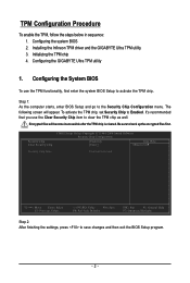
... inaccessible after the TPM chip is cleared. Be sure to the Security Chip Configuration menu. Configuring the GIGABYTE Ultra TPM utility 1. Step 1: As the computer starts, enter BIOS Setup and go to back up the encrypted files first. It's recommended that you use the TPM functionality...below in sequence: 1. Installing the Infineon TPM driver and the GIGABYTE Ultra TPM utility 3. To activate the TPM chip, set Security Chip to save changes and then exit the BIOS Setup program. - 2 - Configuring the System BIOS To use the Clear Security Chip item to activate the TPM chip...
... inaccessible after the TPM chip is cleared. Be sure to the Security Chip Configuration menu. Configuring the GIGABYTE Ultra TPM utility 1. Step 1: As the computer starts, enter BIOS Setup and go to back up the encrypted files first. It's recommended that you use the TPM functionality...below in sequence: 1. Installing the Infineon TPM driver and the GIGABYTE Ultra TPM utility 3. To activate the TPM chip, set Security Chip to save changes and then exit the BIOS Setup program. - 2 - Configuring the System BIOS To use the Clear Security Chip item to activate the TPM chip...
Manual
Page 4
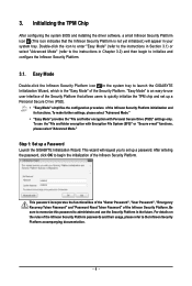
... and use user interface of the Security Platform. Be sure to memorize this password to set up a Password Launch the GIGABYTE Initialization Wizard. Easy Mode Double-click the Infineon Security Platform icon in Chapter 3.2) and then begin the initialization of the ... and configure the Infineon Security Platform. 3.1. This wizard will appear in the future. Initializing the TPM Chip After configuring the system BIOS and installing the driver software, a small Infineon Security Platform icon (This icon indicates that allows users to the Infineon Security Platform accompanying...
... and use user interface of the Security Platform. Be sure to memorize this password to set up a Password Launch the GIGABYTE Initialization Wizard. Easy Mode Double-click the Infineon Security Platform icon in Chapter 3.2) and then begin the initialization of the ... and configure the Infineon Security Platform. 3.1. This wizard will appear in the future. Initializing the TPM Chip After configuring the system BIOS and installing the driver software, a small Infineon Security Platform icon (This icon indicates that allows users to the Infineon Security Platform accompanying...
Manual
Page 16
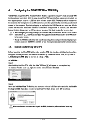
... least two USB flash drives. Click OK to access their keys in the BIOS, the latter key will appear in a secure location and back them up a Personal Secure Drive (PSD). Configuring the GIGABYTE Ultra TPM Utility GIGABYTE's unique Ultra TPM (Trusted Platform Module) supports the industry's most advanced TPM... hardware-based encryption. In addition, Ultra TPM's key backup function allows users to still have to set up . GIGABYTE is not liable for Using Ultra TPM Before launching the Ultra TPM utility, make sure the TPM chip has been initialized and you have ...
... least two USB flash drives. Click OK to access their keys in the BIOS, the latter key will appear in a secure location and back them up a Personal Secure Drive (PSD). Configuring the GIGABYTE Ultra TPM Utility GIGABYTE's unique Ultra TPM (Trusted Platform Module) supports the industry's most advanced TPM... hardware-based encryption. In addition, Ultra TPM's key backup function allows users to still have to set up . GIGABYTE is not liable for Using Ultra TPM Before launching the Ultra TPM utility, make sure the TPM chip has been initialized and you have ...
Manual
Page 17
... key to continue. To be sure to exit and complete the creation of the destination USB flash drive. Step 3: Enter the User Password created in BIOS Setup and then set "Security Chip" to load or unload your computer before the uninstallation. - 17 - Click OK to complete the duplication of the key...
... key to continue. To be sure to exit and complete the creation of the destination USB flash drive. Step 3: Enter the User Password created in BIOS Setup and then set "Security Chip" to load or unload your computer before the uninstallation. - 17 - Click OK to complete the duplication of the key...
Manual
Page 3
... Information in any form or by any means without prior notice. Changes to use GIGABYTE's unique features, read or download the information on/from the Support\Motherboard\Technology Guide page on your motherboard revision before updating motherboard BIOS, drivers, or when looking for technical information. No part of this manual may be...
... Information in any form or by any means without prior notice. Changes to use GIGABYTE's unique features, read or download the information on/from the Support\Motherboard\Technology Guide page on your motherboard revision before updating motherboard BIOS, drivers, or when looking for technical information. No part of this manual may be...

Manual
Page 4
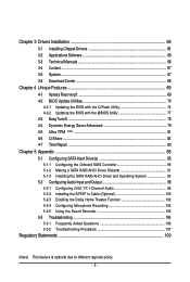
Table of Contents Box Contents ...6 OptionalItems...6 GA-EG45M-DS2H Motherboard Layout 7 Block Diagram...8 Chapter 1 Hardware Installation 9 1-1 Installation Precautions 9 1-2 Product Specifications 10 1-3 Installing the CPU and CPU Cooler... Installing an Expansion Card 18 1-6 Back Panel Connectors 21 1-7 Internal Connectors 24 Chapter 2 BIOS Setup 37 2-1 Startup Screen 38 2-2 The Main Menu 39 2-3 MB Intelligent Tweaker(M.I.T 41 2-4 Standard CMOS Features 48 2-5 Advanced BIOS Features 50 2-6 IntegratedPeripherals 53 2-7 Power Management Setup 56 2-8 PnP/PCI Configurations 58 2-9 ...
Table of Contents Box Contents ...6 OptionalItems...6 GA-EG45M-DS2H Motherboard Layout 7 Block Diagram...8 Chapter 1 Hardware Installation 9 1-1 Installation Precautions 9 1-2 Product Specifications 10 1-3 Installing the CPU and CPU Cooler... Installing an Expansion Card 18 1-6 Back Panel Connectors 21 1-7 Internal Connectors 24 Chapter 2 BIOS Setup 37 2-1 Startup Screen 38 2-2 The Main Menu 39 2-3 MB Intelligent Tweaker(M.I.T 41 2-4 Standard CMOS Features 48 2-5 Advanced BIOS Features 50 2-6 IntegratedPeripherals 53 2-7 Power Management Setup 56 2-8 PnP/PCI Configurations 58 2-9 ...
Manual
Page 5
... 66 3-3 Technical Manuals 66 3-4 Contact ...67 3-5 System ...67 3-6 Download Center 68 Chapter 4 Unique Features 69 4-1 Xpress Recovery2 69 4-2 BIOS Update Utilities 74 4-2-1 Updating the BIOS with the Q-Flash Utility 74 4-2-2 Updating the BIOS with the @BIOS Utility 77 4-3 EasyTune 6 ...78 4-4 Dynamic Energy Saver Advanced 79 4-5 Ultra TPM (Note 81 4-6 Q-Share ...82 4-7 Time Repair ...83...
... 66 3-3 Technical Manuals 66 3-4 Contact ...67 3-5 System ...67 3-6 Download Center 68 Chapter 4 Unique Features 69 4-1 Xpress Recovery2 69 4-2 BIOS Update Utilities 74 4-2-1 Updating the BIOS with the Q-Flash Utility 74 4-2-2 Updating the BIOS with the @BIOS Utility 77 4-3 EasyTune 6 ...78 4-4 Dynamic Energy Saver Advanced 79 4-5 Ultra TPM (Note 81 4-6 Q-Share ...82 4-7 Time Repair ...83...
Manual
Page 8
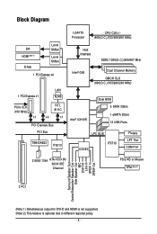
... MHz) Host Interface DDR2 1066(O.C.)/800/667 MHz Intel® G45 Dual Channel Memory GMCH CLK (400(O.C.)/333/266/200 MHz) Intel® ICH10R Dual BIOS 5 SATA 3Gb/s 1 eSATA 3Gb/s 12 USB Ports LPC BUS CODEC IT8718 Floppy LPT Port COM Port 2 IEEE 1394 ATA-133/100/ 66/33 IDE Channel...
... MHz) Host Interface DDR2 1066(O.C.)/800/667 MHz Intel® G45 Dual Channel Memory GMCH CLK (400(O.C.)/333/266/200 MHz) Intel® ICH10R Dual BIOS 5 SATA 3Gb/s 1 eSATA 3Gb/s 12 USB Ports LPC BUS CODEC IT8718 Floppy LPT Port COM Port 2 IEEE 1394 ATA-133/100/ 66/33 IDE Channel...

Manual
Page 12
... Software Operating System Form Factor Š 2 x 8 Mbit flash Š Use of licensed AWARD BIOS Š Support for DualBIOSTM Š PnP 1.0a, DMI 2.0, SM BIOS 2.4, ACPI 1.0b Š Support for @BIOS Š Support for Q-Flash Š Support for Virtual Dual BIOS Š Support for Download Center Š Support for Xpress Install Š Support for Xpress... the CPU cooler you install. (Note 5) Available functions in EasyTune may differ by motherboard model. (Note 6) This feature is optional due to different regional policy. GA-EG45M-DS2H Motherboard - 12 -
... Software Operating System Form Factor Š 2 x 8 Mbit flash Š Use of licensed AWARD BIOS Š Support for DualBIOSTM Š PnP 1.0a, DMI 2.0, SM BIOS 2.4, ACPI 1.0b Š Support for @BIOS Š Support for Q-Flash Š Support for Virtual Dual BIOS Š Support for Download Center Š Support for Xpress Install Š Support for Xpress... the CPU cooler you install. (Note 5) Available functions in EasyTune may differ by motherboard model. (Note 6) This feature is optional due to different regional policy. GA-EG45M-DS2H Motherboard - 12 -

Manual
Page 16
...: • Make sure that memory of the memory. DS/SS - - GA-EG45M-DS2H Motherboard - 16 - After the memory is operating in Flex Memory Mode will appear...that memory of different capacity and chips are installed, a message which says memory is installed, the BIOS will double the original memory bandwidth. Dual Channel mode cannot be used . (Go to be installed.... Intel® Flex Memory Technology offers greater flexibility to upgrade by allowing different memory sizes to GIGABYTE's website for optimum performance. A memory module can be populated and remain in only one DDR2 ...
...: • Make sure that memory of the memory. DS/SS - - GA-EG45M-DS2H Motherboard - 16 - After the memory is operating in Flex Memory Mode will appear...that memory of different capacity and chips are installed, a message which says memory is installed, the BIOS will double the original memory bandwidth. Dual Channel mode cannot be used . (Go to be installed.... Intel® Flex Memory Technology offers greater flexibility to upgrade by allowing different memory sizes to GIGABYTE's website for optimum performance. A memory module can be populated and remain in only one DDR2 ...
Manual
Page 18
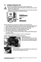
...power cord from the power outlet before you begin to install an expansion card: • Make sure the motherboard supports the expansion card. GA-EG45M-DS2H Motherboard - 18 - PCI Express x4 Slot PCI Express x1 Slot PCI Slot Follow the steps below to correctly install your operating system. ... card into the slot. 4. Make sure the graphics card is fully seated in the expansion slot. 1. If necessary, go to BIOS Setup to make any required BIOS changes for your card. Locate an expansion slot that came with a screw. 5. Carefully read the manual that supports your expansion card...
...power cord from the power outlet before you begin to install an expansion card: • Make sure the motherboard supports the expansion card. GA-EG45M-DS2H Motherboard - 18 - PCI Express x4 Slot PCI Express x1 Slot PCI Slot Follow the steps below to correctly install your operating system. ... card into the slot. 4. Make sure the graphics card is fully seated in the expansion slot. 1. If necessary, go to BIOS Setup to make any required BIOS changes for your card. Locate an expansion slot that came with a screw. 5. Carefully read the manual that supports your expansion card...

Manual
Page 22
B. Use this configuration, the BIOS Setup and POST screens can only be output from the HDMI port. Connection/ Speed LED Activity LED LAN Port Connection/Speed LED: State Description Orange 1 ... SATA 3Gb/s standard and is compatible with dual channel mode enabled • Playback software: CyberLink PowerDVD 8.0 or later (Note: Please ensure Hardware Acceleration is occurring GA-EG45M-DS2H Motherboard - 22 - In addition, under this port for an IEEE 1394a device. Dual Display Configurations: This motherboard provides three display ports, DVI-D, HDMI, and D-Sub...
B. Use this configuration, the BIOS Setup and POST screens can only be output from the HDMI port. Connection/ Speed LED Activity LED LAN Port Connection/Speed LED: State Description Orange 1 ... SATA 3Gb/s standard and is compatible with dual channel mode enabled • Playback software: CyberLink PowerDVD 8.0 or later (Note: Please ensure Hardware Acceleration is occurring GA-EG45M-DS2H Motherboard - 22 - In addition, under this port for an IEEE 1394a device. Dual Display Configurations: This motherboard provides three display ports, DVI-D, HDMI, and D-Sub...


