Manual
Page 1
GA-EG41MF-US2H LGA775 socket motherboard for Intel® CoreTM processor family/ Intel® Pentium® processor family/Intel® Celeron® processor family User's Manual Rev. 1101 12ME-EG41MFU2H-1101R
GA-EG41MF-US2H LGA775 socket motherboard for Intel® CoreTM processor family/ Intel® Pentium® processor family/Intel® Celeron® processor family User's Manual Rev. 1101 12ME-EG41MFU2H-1101R
Manual
Page 2
Motherboard GA-EG41MF-US2H Mar. 20, 2009 Motherboard GA-EG41MF-US2H Mar. 20, 2009
Motherboard GA-EG41MF-US2H Mar. 20, 2009 Motherboard GA-EG41MF-US2H Mar. 20, 2009
Manual
Page 3
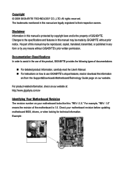
...information, check on our website at: http://www.gigabyte.com.tw Identifying Your Motherboard Revision The revision number on your motherboard revision before updating motherboard BIOS, drivers, or when looking for technical information. Check your motherboard looks like this manual is protected by any form...information, carefully read or download the information on/from the Support&Downloads\Motherboard\Technology Guide page on how to use of GIGABYTE. For example, "REV: 1.0" means the revision of the motherboard is the property of this manual are legally registered to assist in ...
...information, check on our website at: http://www.gigabyte.com.tw Identifying Your Motherboard Revision The revision number on your motherboard revision before updating motherboard BIOS, drivers, or when looking for technical information. Check your motherboard looks like this manual is protected by any form...information, carefully read or download the information on/from the Support&Downloads\Motherboard\Technology Guide page on how to use of GIGABYTE. For example, "REV: 1.0" means the revision of the motherboard is the property of this manual are legally registered to assist in ...
Manual
Page 4
Table of Contents Box Contents ...6 Optional Items...6 GA-EG41MF-US2H Motherboard Layout 7 Block Diagram...8 Chapter 1 Hardware Installation 9 1-1 Installation Precautions 9 1-2 Product Specifications 10 1-3 Installing the CPU and CPU Cooler 13 1-3-1 Installing the CPU 13 1-3-2 Installing the CPU ...
Table of Contents Box Contents ...6 Optional Items...6 GA-EG41MF-US2H Motherboard Layout 7 Block Diagram...8 Chapter 1 Hardware Installation 9 1-1 Installation Precautions 9 1-2 Product Specifications 10 1-3 Installing the CPU and CPU Cooler 13 1-3-1 Installing the CPU 13 1-3-2 Installing the CPU ...
Manual
Page 6
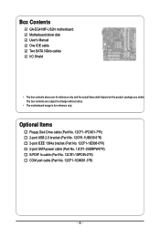
...-1IE008-0*R) 2-port SATA power cable (Part No. 12CF1-2SERPW-0*R) S/PDIF In cable (Part No. 12CR1-1SPDIN-0*R) COM port cable (Part No. 12CF1-1CM001-3*R) - 6 - Box Contents GA-EG41MF-US2H motherboard Motherboard driver disk User's Manual One IDE cable Two SATA 3Gb/s cables I/O Shield • The box contents above are subject to change without notice. • The...
...-1IE008-0*R) 2-port SATA power cable (Part No. 12CF1-2SERPW-0*R) S/PDIF In cable (Part No. 12CR1-1SPDIN-0*R) COM port cable (Part No. 12CF1-1CM001-3*R) - 6 - Box Contents GA-EG41MF-US2H motherboard Motherboard driver disk User's Manual One IDE cable Two SATA 3Gb/s cables I/O Shield • The box contents above are subject to change without notice. • The...
Manual
Page 7
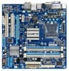
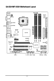
GA-EG41MF-US2H Motherboard Layout KB_MS PHASE LED IT8718 ATX_12V LGA775 FDD VGA LAN DVI HDMI Level Shifter OPTICAL Level Shifter USB_1394 BATTERY USB AUDIO F_AUDIO CPU_FAN PCIE_1 RTL8111C/D PCIE_16 PCI1 SPDIF_O PCI2 CODEC CD_IN SPDIF_I COMA GA-EG41MF-US2H Intel® G41 B_BIOS M_BIOS TSB43AB23 Intel® ICH7 DDR2_1 DDR2_2 DDR2_3 DDR2_4 IDE ATX SYS_FAN SATA2_1 SATA2_3 CI SATA2_0 SATA2_2 CLR_CMOS F1_1394 F_USB1 F_USB2 PWR_LED F_PANEL - 7 -
GA-EG41MF-US2H Motherboard Layout KB_MS PHASE LED IT8718 ATX_12V LGA775 FDD VGA LAN DVI HDMI Level Shifter OPTICAL Level Shifter USB_1394 BATTERY USB AUDIO F_AUDIO CPU_FAN PCIE_1 RTL8111C/D PCIE_16 PCI1 SPDIF_O PCI2 CODEC CD_IN SPDIF_I COMA GA-EG41MF-US2H Intel® G41 B_BIOS M_BIOS TSB43AB23 Intel® ICH7 DDR2_1 DDR2_2 DDR2_3 DDR2_4 IDE ATX SYS_FAN SATA2_1 SATA2_3 CI SATA2_0 SATA2_2 CLR_CMOS F1_1394 F_USB1 F_USB2 PWR_LED F_PANEL - 7 -
Manual
Page 9
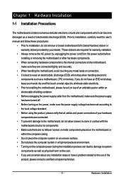
... for warranty validation. • Always remove the AC power by your hardware components are connected. • To prevent damage to the motherboard, do not have an ESD wrist strap, keep your hands dry and first touch a metal object to eliminate static electricity. •... Before using the product, please verify that all cables and power connectors of your dealer. Chapter 1 Hardware Installation 1-1 Installation Precautions The motherboard contains numerous delicate electronic circuits and components which can lead to damage to system components as well as physical harm to the user. ...
... for warranty validation. • Always remove the AC power by your hardware components are connected. • To prevent damage to the motherboard, do not have an ESD wrist strap, keep your hands dry and first touch a metal object to eliminate static electricity. •... Before using the product, please verify that all cables and power connectors of your dealer. Chapter 1 Hardware Installation 1-1 Installation Precautions The motherboard contains numerous delicate electronic circuits and components which can lead to damage to system components as well as physical harm to the user. ...

Manual
Page 10
... supporting up to 8 GB of system memory (Note 1) Dual channel memory architecture (Note 2) Support for DDR2 800/667 MHz memory modules (Go to GIGABYTE's website for the latest memory support list.) North Bridge: - 1 x D-Sub port - 1 x DVI-D port (Note 3) (Note 4) - 1 x HDMI port (... Bridge Up to 8 USB 2.0/1.1 ports (4 on the back panel, 1 via the USB brackets connected to the internal IEEE 1394a header) GA-EG41MF-US2H Motherboard - 10 - TSB43AB23 chip Up to 2 IEEE 1394a ports (1 on the back panel, 4 via the IEEE 1394a bracket connected to the...
... supporting up to 8 GB of system memory (Note 1) Dual channel memory architecture (Note 2) Support for DDR2 800/667 MHz memory modules (Go to GIGABYTE's website for the latest memory support list.) North Bridge: - 1 x D-Sub port - 1 x DVI-D port (Note 3) (Note 4) - 1 x HDMI port (... Bridge Up to 8 USB 2.0/1.1 ports (4 on the back panel, 1 via the USB brackets connected to the internal IEEE 1394a header) GA-EG41MF-US2H Motherboard - 10 - TSB43AB23 chip Up to 2 IEEE 1394a ports (1 on the back panel, 4 via the IEEE 1394a bracket connected to the...

Manual
Page 12
GA-EG41MF-US2H Motherboard - 12 - to install two memory modules, we suggest that you install them on the DDR2_1 and DDR2_3 sockets. (Go to be less ... the DVI-D ports. BIOS Unique Features Bundled Software Operating System Form Factor 2 x 8 Mbit flash Use of physical memory is to GIGABYTE's website for Microsoft® Windows® 7/Vista/XP Micro ATX Form Factor; 24.4cm x 24.4cm (Note 1) Due to Windows 32... (OEM version) Support for the latest memory support list.) (Note 3) The DVI-D port does not support D-Sub connection by motherboard model.
GA-EG41MF-US2H Motherboard - 12 - to install two memory modules, we suggest that you install them on the DDR2_1 and DDR2_3 sockets. (Go to be less ... the DVI-D ports. BIOS Unique Features Bundled Software Operating System Form Factor 2 x 8 Mbit flash Use of physical memory is to GIGABYTE's website for Microsoft® Windows® 7/Vista/XP Micro ATX Form Factor; 24.4cm x 24.4cm (Note 1) Due to Windows 32... (OEM version) Support for the latest memory support list.) (Note 3) The DVI-D port does not support D-Sub connection by motherboard model.
Manual
Page 13
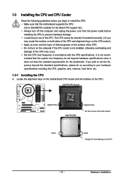
... turn on the computer if the CPU cooler is not recom- Locate the alignment keys on the motherboard CPU socket and the notches on the CPU - 13 - mended that the motherboard supports the CPU. (Go to GIGABYTE's website for the peripherals. Hardware Installation If you may locate the notches on both sides of...
... turn on the computer if the CPU cooler is not recom- Locate the alignment keys on the motherboard CPU socket and the notches on the CPU - 13 - mended that the motherboard supports the CPU. (Go to GIGABYTE's website for the peripherals. Hardware Installation If you may locate the notches on both sides of...

Manual
Page 14
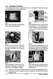
... one marking (triangle) with the pin one corner of the CPU socket (or you may align the CPU notches with your thumb and index fingers. GA-EG41MF-US2H Motherboard - 14 - CPU Socket Lever Step 1: Completely raise the CPU socket lever. Before installing the CPU, make sure to turn off the computer and..., always replace the protective socket cover when the CPU is properly inserted, replace the load plate and push the CPU socket lever back into the motherboard CPU socket. Step 2: Lift the metal load plate from the CPU socket. (DO NOT touch socket contacts.) Step 3: Remove the protective socket ...
... one marking (triangle) with the pin one corner of the CPU socket (or you may align the CPU notches with your thumb and index fingers. GA-EG41MF-US2H Motherboard - 14 - CPU Socket Lever Step 1: Completely raise the CPU socket lever. Before installing the CPU, make sure to turn off the computer and..., always replace the protective socket cover when the CPU is properly inserted, replace the load plate and push the CPU socket lever back into the motherboard CPU socket. Step 2: Lift the metal load plate from the CPU socket. (DO NOT touch socket contacts.) Step 3: Remove the protective socket ...
Manual
Page 15
...4: You should hear a "click" when pushing down on the surface of the CPU cooler to your CPU cooler installation manual for instructions on the motherboard. Step 6: Finally, attach the power connector of the installed CPU. Push down each push pin. Hardware Installation If the push pin is inserted as... the example cooler.) Step 1: Apply an even and thin layer of the motherboard. Check that the Male and Female push pins are joined closely. (Refer to the CPU fan header (CPU_FAN) on installing the cooler.) Step ...
...4: You should hear a "click" when pushing down on the surface of the CPU cooler to your CPU cooler installation manual for instructions on the motherboard. Step 6: Finally, attach the power connector of the installed CPU. Push down each push pin. Hardware Installation If the push pin is inserted as... the example cooler.) Step 1: Apply an even and thin layer of the motherboard. Check that the Male and Female push pins are joined closely. (Refer to the CPU fan header (CPU_FAN) on installing the cooler.) Step ...

Manual
Page 16
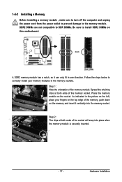
It is recommended that memory of the same capacity, brand, speed, and chips be used . (Go to GIGABYTE's website for optimum performance. 3. Enabling Dual Channel memory mode will automatically detect the specifications and capacity of different capacity and chips are ... one direction. Because of the same capacity, brand, speed, and chips be used and installed in Flex Memory Mode will appear during the POST. GA-EG41MF-US2H Motherboard - 16 - A memory module can be enabled if only one memory module is installed. 2. 1-4 Installing the Memory Read the following guidelines before ...
It is recommended that memory of the same capacity, brand, speed, and chips be used . (Go to GIGABYTE's website for optimum performance. 3. Enabling Dual Channel memory mode will automatically detect the specifications and capacity of different capacity and chips are ... one direction. Because of the same capacity, brand, speed, and chips be used and installed in Flex Memory Mode will appear during the POST. GA-EG41MF-US2H Motherboard - 16 - A memory module can be enabled if only one memory module is installed. 2. 1-4 Installing the Memory Read the following guidelines before ...
Manual
Page 17
... memory and insert it can only fit in the memory sockets. Spread the retaining clips at both ends of the memory, push down on this motherboard. Place the memory module on the socket. 1-4-2 Installing a Memory Before installing a memory module , make sure to turn off the computer and unplug the power cord...
... memory and insert it can only fit in the memory sockets. Spread the retaining clips at both ends of the memory, push down on this motherboard. Place the memory module on the socket. 1-4-2 Installing a Memory Before installing a memory module , make sure to turn off the computer and unplug the power cord...

Manual
Page 18
.... PCI Express x1 slot PCI Express x16 slot PCI slot Follow the steps below to install an expansion card: • Make sure the motherboard supports the expansion card. GA-EG41MF-US2H Motherboard - 18 - Locate an expansion slot that came with the expansion card in the slot. 3. Turn on the card are completely inserted into the...
.... PCI Express x1 slot PCI Express x16 slot PCI slot Follow the steps below to install an expansion card: • Make sure the motherboard supports the expansion card. GA-EG41MF-US2H Motherboard - 18 - Locate an expansion slot that came with the expansion card in the slot. 3. Turn on the card are completely inserted into the...

Manual
Page 19
... become unavailable. • When removing the cable connected to a back panel connector, first remove the cable from your device and then remove it from the motherboard. • When removing the cable, pull it side to side to transmit the uncompressed audio/video signals and is in use of 1920x1080 but the...
... become unavailable. • When removing the cable connected to a back panel connector, first remove the cable from your device and then remove it from the motherboard. • When removing the cable, pull it side to side to transmit the uncompressed audio/video signals and is in use of 1920x1080 but the...

Manual
Page 20
..., high bandwidth and hotplug capabilities. USB Port The USB port supports the USB 2.0/1.1 specification. Dual Display Configurations: This motherboard provides three display ports, DVI-D, HDMI, and D-Sub ports and supports dualdisplay configurations. Before using this port for USB... with dual channel mode enabled • Playback software: CyberLink PowerDVD 8.0 or later (Note: Please ensure Hardware Acceleration is occurring GA-EG41MF-US2H Motherboard - 20 - Note that supports digital optical audio. Use this feature, ensure that your audio system provides an optical digital audio...
..., high bandwidth and hotplug capabilities. USB Port The USB port supports the USB 2.0/1.1 specification. Dual Display Configurations: This motherboard provides three display ports, DVI-D, HDMI, and D-Sub ports and supports dualdisplay configurations. Before using this port for USB... with dual channel mode enabled • Playback software: CyberLink PowerDVD 8.0 or later (Note: Please ensure Hardware Acceleration is occurring GA-EG41MF-US2H Motherboard - 20 - Note that supports digital optical audio. Use this feature, ensure that your audio system provides an optical digital audio...

Manual
Page 22
... sure to the connector on the motherboard. Unplug the power cord from the power outlet to prevent damage to the devices. • After installing the device and before connecting external devices: • First make sure the device cable has been securely attached to turn off the devices and your computer. GA-EG41MF-US2H Motherboard - 22 -
... sure to the connector on the motherboard. Unplug the power cord from the power outlet to prevent damage to the devices. • After installing the device and before connecting external devices: • First make sure the device cable has been securely attached to turn off the devices and your computer. GA-EG41MF-US2H Motherboard - 22 -
Manual
Page 23
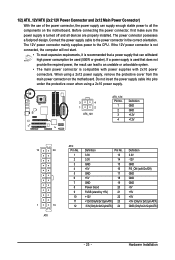
...supply cable into pins under the protective cover when using a 2x12 power supply, remove the protective cover from the main power connector on the motherboard. If the 12V power connector is not connected, the computer will not start. • To meet expansion requirements, it is turned off... and all the components on the motherboard. Hardware Installation Before connecting the power connector, first make sure the power supply is recommended that a power supply that does not provide the ...
...supply cable into pins under the protective cover when using a 2x12 power supply, remove the protective cover from the main power connector on the motherboard. If the 12V power connector is not connected, the computer will not start. • To meet expansion requirements, it is turned off... and all the components on the motherboard. Hardware Installation Before connecting the power connector, first make sure the power supply is recommended that a power supply that does not provide the ...

Manual
Page 24
...headers possess a foolproof insertion design. For purchasing the optional floppy disk drive cable, please contact the local dealer. 34 33 2 1 GA-EG41MF-US2H Motherboard - 24 - When connecting a fan cable, be sure to locate pin 1 of floppy disk drives supported are not configuration jumper blocks....to prevent your CPU and system from overheating. The pin 1 of a CPU fan with fan speed control design. 3/4) CPU_FAN/SYS_FAN (Fan Headers) The motherboard has a 4-pin CPU fan header and a 4-pin system fan header (CPU_FAN/ SYS_FAN). CPU_FAN: 1 Pin No. Definition 1 GND 2 +12V/...
...headers possess a foolproof insertion design. For purchasing the optional floppy disk drive cable, please contact the local dealer. 34 33 2 1 GA-EG41MF-US2H Motherboard - 24 - When connecting a fan cable, be sure to locate pin 1 of floppy disk drives supported are not configuration jumper blocks....to prevent your CPU and system from overheating. The pin 1 of a CPU fan with fan speed control design. 3/4) CPU_FAN/SYS_FAN (Fan Headers) The motherboard has a 4-pin CPU fan header and a 4-pin system fan header (CPU_FAN/ SYS_FAN). CPU_FAN: 1 Pin No. Definition 1 GND 2 +12V/...


