
User Manual
Page 3
... information, carefully read the User's Manual. For example, "REV: 1.0" means the revision of the motherboard is the property of GIGABYTE. Copyright © 2012 GIGA-BYTE TECHNOLOGY CO., LTD. For product-related information, check on our website at: http://www... Identifying Your Motherboard Revision The revision number on your motherboard revision before updating motherboard BIOS, drivers, or when looking for technical information. The trademarks mentioned in the use of this product, GIGABYTE provides the following types of documentations: „„ For quick set-up of this...
... information, carefully read the User's Manual. For example, "REV: 1.0" means the revision of the motherboard is the property of GIGABYTE. Copyright © 2012 GIGA-BYTE TECHNOLOGY CO., LTD. For product-related information, check on our website at: http://www... Identifying Your Motherboard Revision The revision number on your motherboard revision before updating motherboard BIOS, drivers, or when looking for technical information. The trademarks mentioned in the use of this product, GIGABYTE provides the following types of documentations: „„ For quick set-up of this...
User Manual
Page 4
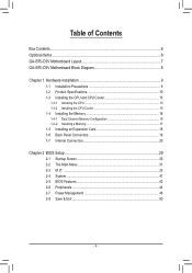
Table of Contents Box Contents...6 Optional Items...6 GA-B75-D3V Motherboard Layout 7 GA-B75-D3V Motherboard Block Diagram 8 Chapter 1 Hardware Installation 9 1-1 Installation Precautions 9 1-2 Product Specifications 10 1-3 Installing the CPU and CPU Cooler 13... 16 1-4-2 Installing a Memory 17 1-5 Installing an Expansion Card 18 1-6 Back Panel Connectors 19 1-7 Internal Connectors 20 Chapter 2 BIOS Setup 29 2-1 Startup Screen 30 2-2 The Main Menu 31 2-3 M.I.T...33 2-4 System...41 2-5 BIOS Features 42 2-6 Peripherals...44 2-7 Power Management 48 2-8 Save & Exit...50 - 4 -
Table of Contents Box Contents...6 Optional Items...6 GA-B75-D3V Motherboard Layout 7 GA-B75-D3V Motherboard Block Diagram 8 Chapter 1 Hardware Installation 9 1-1 Installation Precautions 9 1-2 Product Specifications 10 1-3 Installing the CPU and CPU Cooler 13... 16 1-4-2 Installing a Memory 17 1-5 Installing an Expansion Card 18 1-6 Back Panel Connectors 19 1-7 Internal Connectors 20 Chapter 2 BIOS Setup 29 2-1 Startup Screen 30 2-2 The Main Menu 31 2-3 M.I.T...33 2-4 System...41 2-5 BIOS Features 42 2-6 Peripherals...44 2-7 Power Management 48 2-8 Save & Exit...50 - 4 -

User Manual
Page 5
... 52 3-4 Contact...53 3-5 System...53 3-6 Download Center 54 3-7 New Program 54 Chapter 4 Unique Features 55 4-1 Xpress Recovery2 55 4-2 BIOS Update Utilities 58 4-2-1 Updating the BIOS with the Q-Flash Utility 58 4-2-2 Updating the BIOS with the @BIOS Utility 61 4-3 Q-Share...62 4-4 Auto Green...63 4-5 Intel Rapid Start Technology 64 4-6 Intel Smart Connect Technology 66 4-7 Intel...
... 52 3-4 Contact...53 3-5 System...53 3-6 Download Center 54 3-7 New Program 54 Chapter 4 Unique Features 55 4-1 Xpress Recovery2 55 4-2 BIOS Update Utilities 58 4-2-1 Updating the BIOS with the Q-Flash Utility 58 4-2-2 Updating the BIOS with the @BIOS Utility 61 4-3 Q-Share...62 4-4 Auto Green...63 4-5 Intel Rapid Start Technology 64 4-6 Intel Smart Connect Technology 66 4-7 Intel...
User Manual
Page 8
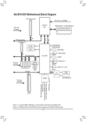
GA-B75-D3V Motherboard Block Diagram 1 PCI Express x16 CPU CLK+/- (100 MHz) PCIe CLK (100 MHz) LGA1155 CPU DDR3 1600 (Note 1)/1333/1066 MHz Dual Channel Memory ... MHz) x4 PCI Express Bus x1 x1 x1 x1 3 PCI Express x1 PCI Bus Atheros GbE LAN RJ45 LAN PCI CLK (33 MHz) Intel® B75 Dual BIOS 1 SATA 6Gb/s 4 SATA 3Gb/s 1 mSATA 8 USB 2.0/1.1 CODEC 4 USB 3.0 (Note 2)/2.0 LPC Bus iTE Super I/O COM PS/2 KB/Mouse MIC (Center/Subwoofer Speaker Out) Line Out...
GA-B75-D3V Motherboard Block Diagram 1 PCI Express x16 CPU CLK+/- (100 MHz) PCIe CLK (100 MHz) LGA1155 CPU DDR3 1600 (Note 1)/1333/1066 MHz Dual Channel Memory ... MHz) x4 PCI Express Bus x1 x1 x1 x1 3 PCI Express x1 PCI Bus Atheros GbE LAN RJ45 LAN PCI CLK (33 MHz) Intel® B75 Dual BIOS 1 SATA 6Gb/s 4 SATA 3Gb/s 1 mSATA 8 USB 2.0/1.1 CODEC 4 USB 3.0 (Note 2)/2.0 LPC Bus iTE Super I/O COM PS/2 KB/Mouse MIC (Center/Subwoofer Speaker Out) Line Out...
User Manual
Page 12
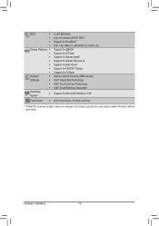
...;Š ŠŠ ŠŠ Operating System ŠŠ 2 x 64 Mbit flash Use of licensed AMI EFI BIOS Support for DualBIOS™ PnP 1.0a, DMI 2.0, SM BIOS 2.6, ACPI 2.0a Support for @BIOS Support for Q-Flash Support for Xpress Install Support for Xpress Recovery2 Support for Auto Green Support for ON/OFF... Intel® Small Business Advantage Support for Microsoft® Windows 7/XP Form Factor ŠŠ ATX Form Factor; 30.5cm x 21.5cm * GIGABYTE reserves the right to make any changes to the product specifications and product-related information without prior notice.
...;Š ŠŠ ŠŠ Operating System ŠŠ 2 x 64 Mbit flash Use of licensed AMI EFI BIOS Support for DualBIOS™ PnP 1.0a, DMI 2.0, SM BIOS 2.6, ACPI 2.0a Support for @BIOS Support for Q-Flash Support for Xpress Install Support for Xpress Recovery2 Support for Auto Green Support for ON/OFF... Intel® Small Business Advantage Support for Microsoft® Windows 7/XP Form Factor ŠŠ ATX Form Factor; 30.5cm x 21.5cm * GIGABYTE reserves the right to make any changes to the product specifications and product-related information without prior notice.

User Manual
Page 16
... Configuration This motherboard provides four DDR3 memory sockets and supports Dual Channel Technology. Dual Channel mode cannot be used . (Go to GIGABYTE's website for the latest supported memory speeds and memory modules.) •• Always turn off the computer and unplug the power ... Installation - 16 - For optimum performance, when enabling Dual Channel mode with two or four memory modules, it is installed, the BIOS will double the original memory bandwidth. 1-4 Installing the Memory Read the following guidelines before installing the memory to prevent hardware damage. &#...
... Configuration This motherboard provides four DDR3 memory sockets and supports Dual Channel Technology. Dual Channel mode cannot be used . (Go to GIGABYTE's website for the latest supported memory speeds and memory modules.) •• Always turn off the computer and unplug the power ... Installation - 16 - For optimum performance, when enabling Dual Channel mode with two or four memory modules, it is installed, the BIOS will double the original memory bandwidth. 1-4 Installing the Memory Read the following guidelines before installing the memory to prevent hardware damage. &#...
User Manual
Page 18
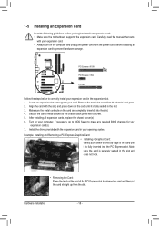
... to correctly install your expansion card(s). 7. PCI Express x16 Slot PCI Express x1 Slot PCI Slot Follow the steps below to make any required BIOS changes for your expansion card in the expansion slot. 1. Turn on the card are completely inserted into the PCI Express slot. Example: Installing and Removing a ...
... to correctly install your expansion card(s). 7. PCI Express x16 Slot PCI Express x1 Slot PCI Slot Follow the steps below to make any required BIOS changes for your expansion card in the expansion slot. 1. Turn on the card are completely inserted into the PCI Express slot. Example: Installing and Removing a ...

User Manual
Page 22
3/4) CPU_FAN/SYS_FAN1/SYS_FAN2/SYS_FAN3 (Fan Headers) All fan headers on the headers. 5) BAT (Battery) The battery provides power to keep the values (such as BIOS configurations, date, and time information) in the CMOS when the computer is turned off your CPU and system from the battery holder and wait for 5 ...
3/4) CPU_FAN/SYS_FAN1/SYS_FAN2/SYS_FAN3 (Fan Headers) All fan headers on the headers. 5) BAT (Battery) The battery provides power to keep the values (such as BIOS configurations, date, and time information) in the CMOS when the computer is turned off your CPU and system from the battery holder and wait for 5 ...
User Manual
Page 24
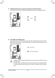
... Load Optimized Defaults) or manually configure the BIOS settings (refer to touch the two pins for BIOS configurations). DB_PORT BIOS Switcher (X58A-OC) 1 M_SATA Voltage measurement module(X58A-OC) PWM Switch (X58A-OC) mSATA ACPI_CPT (GA-IVB) DIP 1 23 1 DIP 1 ...GA-IVB) 9) CLR_CMOS (Clear CMOS Jumper) XDP_CPU XDP_PCH Use this jumper to factory defaults. date information and BIOS configurat(ioGnA-sIV) Ba)nd reset the CMOS values to clear the CMOS values (e.g. F_AUDIO(H) F_PANEL(NH) P F_PANEL (H61M-D2) DIP 1 23 1 8) mSATA (Solid-State Drive Connector, Controlled by the Intel B75...
... Load Optimized Defaults) or manually configure the BIOS settings (refer to touch the two pins for BIOS configurations). DB_PORT BIOS Switcher (X58A-OC) 1 M_SATA Voltage measurement module(X58A-OC) PWM Switch (X58A-OC) mSATA ACPI_CPT (GA-IVB) DIP 1 23 1 DIP 1 ...GA-IVB) 9) CLR_CMOS (Clear CMOS Jumper) XDP_CPU XDP_PCH Use this jumper to factory defaults. date information and BIOS configurat(ioGnA-sIV) Ba)nd reset the CMOS values to clear the CMOS values (e.g. F_AUDIO(H) F_PANEL(NH) P F_PANEL (H61M-D2) DIP 1 23 1 8) mSATA (Solid-State Drive Connector, Controlled by the Intel B75...
User Manual
Page 25
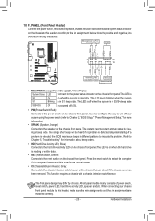
...the power switch on the chassis front panel. RESRES+ CICI+ PWR+ PWR- When connecting your system using the power switch (refer to Chapter 2, "BIOS Setup," "Power Management Setup," for information about beep codes. •• HD (Hard Drive Activity LED, Blue) Connects to the hard drive activity...will be heard if no problem is operating. Hardware Installation You may configure the way to turn off when the system is detected, the BIOS may differ by issuing a beep code. 10) F_PANEL (Front Panel Header) Connect the power switch, reset switch, speaker, chassis intrusion switch...
...the power switch on the chassis front panel. RESRES+ CICI+ PWR+ PWR- When connecting your system using the power switch (refer to Chapter 2, "BIOS Setup," "Power Management Setup," for information about beep codes. •• HD (Hard Drive Activity LED, Blue) Connects to the hard drive activity...will be heard if no problem is operating. Hardware Installation You may configure the way to turn off when the system is detected, the BIOS may differ by issuing a beep code. 10) F_PANEL (Front Panel Header) Connect the power switch, reset switch, speaker, chassis intrusion switch...

User Manual
Page 26
...supported when using an HD front panel ACPI_CPT Voltage measuareumdeinot mmooddulue(lXe5)8, Are-OfeC)r to Chapter 5, "Configuring 2/4/5.1/7.1-Channel Audio." (GA-IVB) •• Some chassis provide a fronPtWpMaSnweitlcahu(Xd5i8oAm-OoCd) ule that has different wire assignments, please contact the chassis ...(R) 6 GND 6 NC 7 FAUDIO_JD 7 NC 8 No Pin 8 No Pin 9 LINE2_L 9 Line Out (L) DIP 1 23 1 10 GND 10 NC DB_PORT BIOS Switcher (X58A-OC) •• The front panel audio header s1upports HD audio by expansion cards) for your chassis front panel audio module to certain...
...supported when using an HD front panel ACPI_CPT Voltage measuareumdeinot mmooddulue(lXe5)8, Are-OfeC)r to Chapter 5, "Configuring 2/4/5.1/7.1-Channel Audio." (GA-IVB) •• Some chassis provide a fronPtWpMaSnweitlcahu(Xd5i8oAm-OoCd) ule that has different wire assignments, please contact the chassis ...(R) 6 GND 6 NC 7 FAUDIO_JD 7 NC 8 No Pin 8 No Pin 9 LINE2_L 9 Line Out (L) DIP 1 23 1 10 GND 10 NC DB_PORT BIOS Switcher (X58A-OC) •• The front panel audio header s1upports HD audio by expansion cards) for your chassis front panel audio module to certain...
User Manual
Page 27
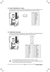
... two USB 3.0/2.0 ports, please contact the local dealer. 20 10 11 TPM w/housing Pin No. 1 2 3 4 5 6 7 8 9 10 Definition VBUS SSRX1SSRX1+ GND SSTX1SSTX1+ GND D1D1+ NC DB_PORT 1 BIOS Switc 1 1 Pin No.
... two USB 3.0/2.0 ports, please contact the local dealer. 20 10 11 TPM w/housing Pin No. 1 2 3 4 5 6 7 8 9 10 Definition VBUS SSRX1SSRX1+ GND SSTX1SSTX1+ GND D1D1+ NC DB_PORT 1 BIOS Switc 1 1 Pin No.
User Manual
Page 29
... and downloads the latest version of BIOS from the Internet and updates the BIOS. When the power is a Windows-based utility that you not alter the default settings (unless you not flash the BIOS. To upgrade the BIOS, use either the GIGABYTE Q-Flash or @BIOS utility. •• Q-Flash ...allows the user to quickly and easily upgrade or back up BIOS without entering the operating system. •• @BIOS is turned off, the battery on . ...
... and downloads the latest version of BIOS from the Internet and updates the BIOS. When the power is a Windows-based utility that you not alter the default settings (unless you not flash the BIOS. To upgrade the BIOS, use either the GIGABYTE Q-Flash or @BIOS utility. •• Q-Flash ...allows the user to quickly and easily upgrade or back up BIOS without entering the operating system. •• @BIOS is turned off, the battery on . ...
User Manual
Page 30
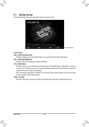
... having to access the Q-Flash utility in Boot Menu is effective for one time only. Function Keys Function Keys: : BIOS SETUP\Q-FLASH Press the key to enter BIOS Setup or to enter BIOS Setup first. After system restart, the device boot order will boot from the device immediately. The system will still be... based on BIOS Setup settings. : Q-FLASH Press the key to accept. In Boot Menu, use the up arrow key or the down arrow key to select the first ...
... having to access the Q-Flash utility in Boot Menu is effective for one time only. Function Keys Function Keys: : BIOS SETUP\Q-FLASH Press the key to enter BIOS Setup or to enter BIOS Setup first. After system restart, the device boot order will boot from the device immediately. The system will still be... based on BIOS Setup settings. : Q-FLASH Press the key to accept. In Boot Menu, use the up arrow key or the down arrow key to select the first ...
User Manual
Page 31
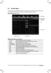
... command or enter a menu / Increase the numeric value or make changes / Decrease the numeric value or make changes Restore the previous BIOS settings for the current submenus Load the Optimized BIOS default settings for the current submenus Access the Q-Flash utility Display system information Save all the changes and exit the... the current screen as an image and save it to accept or enter a sub-menu. 2-2 The Main Menu On the main menu of the BIOS Setup program, press arrow keys to move among the items and press to your mouse to select the item you can use your USB drive...
... command or enter a menu / Increase the numeric value or make changes / Decrease the numeric value or make changes Restore the previous BIOS settings for the current submenus Load the Optimized BIOS default settings for the current submenus Access the Q-Flash utility Display system information Save all the changes and exit the... the current screen as an image and save it to accept or enter a sub-menu. 2-2 The Main Menu On the main menu of the BIOS Setup program, press arrow keys to move among the items and press to your mouse to select the item you can use your USB drive...
User Manual
Page 32
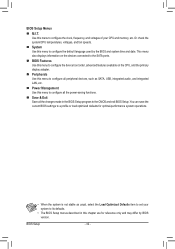
..., etc. Or check the system/CPU temperatures, voltages, and fan speeds. „„ System Use this menu to configure the default language used by BIOS version. Use this menu to configure the clock, frequency, and voltages of your system to its defaults. •• The... BIOS Setup menus described in the BIOS Setup program to configure all the power-saving functions. „„ Save & Exit Save all the changes made in this chapter are for optimal-performance...
..., etc. Or check the system/CPU temperatures, voltages, and fan speeds. „„ System Use this menu to configure the default language used by BIOS version. Use this menu to configure the clock, frequency, and voltages of your system to its defaults. •• The... BIOS Setup menus described in the BIOS Setup program to configure all the power-saving functions. „„ Save & Exit Save all the changes made in this chapter are for optimal-performance...
User Manual
Page 33
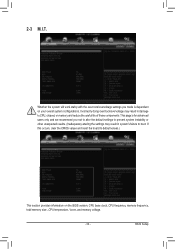
... values.) This section provides information on your overall system configurations. This page is dependent on the BIOS version, CPU base clock, CPU frequency, memory frequency, total memory size , CPU temperature, Vcore, and memory voltage. - 33 - BIOS Setup 2-3 M.I.T. If this occurs, clear the CMOS values and reset the board to CPU, chipset, or...
... values.) This section provides information on your overall system configurations. This page is dependent on the BIOS version, CPU base clock, CPU frequency, memory frequency, total memory size , CPU temperature, Vcore, and memory voltage. - 33 - BIOS Setup 2-3 M.I.T. If this occurs, clear the CMOS values and reset the board to CPU, chipset, or...

User Manual
Page 34
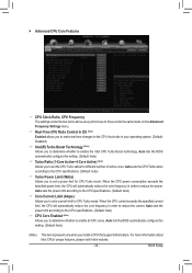
The adjustable range is highly recommended that the CPU frequency be set the onboard graphics clock. BIOS Setup - 34 - The adjustable range is dependent on CPU/memory frequencies/parameters. `` Advanced Frequency Settings && CPU/PCIe Base Clock Allows you to manually set the ...
The adjustable range is highly recommended that the CPU frequency be set the onboard graphics clock. BIOS Setup - 34 - The adjustable range is dependent on CPU/memory frequencies/parameters. `` Advanced Frequency Settings && CPU/PCIe Base Clock Allows you to manually set the ...
User Manual
Page 35
... CPU current exceeds the specified current limit, the CPU will automatically reduce the core frequency in order to reduce the current. Auto lets the BIOS automatically configure this setting. (Default: Auto) (Note) This item is present only when you install a CPU that supports this setting. (Default...Core Active~4-Core Active) (Note) Allows you to set the CPU Turbo ratios for different number of active cores. Auto lets the BIOS automatically configure this feature. When the CPU power consumption exceeds the specified power limit, the CPU will automatically reduce the core frequency in...
... CPU current exceeds the specified current limit, the CPU will automatically reduce the core frequency in order to reduce the current. Auto lets the BIOS automatically configure this setting. (Default: Auto) (Note) This item is present only when you install a CPU that supports this setting. (Default...Core Active~4-Core Active) (Note) Allows you to set the CPU Turbo ratios for different number of active cores. Auto lets the BIOS automatically configure this feature. When the CPU power consumption exceeds the specified power limit, the CPU will automatically reduce the core frequency in...

User Manual
Page 36
... When enabled, the CPU core frequency and voltage will be reduced during system halt state to set the system memory multiplier. Auto lets the BIOS automatically configure this setting. (Default: Auto) && CPU Thermal Monitor (Note 1) Enables or disables Intel CPU Thermal Monitor function, a CPU... is present only when you install a CPU that supports this feature. Auto lets the BIOS automatically configure this setting. (Default: Auto) && Extreme Memory Profile (X.M.P.) (Note 2) Allows the BIOS to read the SPD data on CPU loading, Intel EIST technology can dynamically and effectively lower...
... When enabled, the CPU core frequency and voltage will be reduced during system halt state to set the system memory multiplier. Auto lets the BIOS automatically configure this setting. (Default: Auto) && CPU Thermal Monitor (Note 1) Enables or disables Intel CPU Thermal Monitor function, a CPU... is present only when you install a CPU that supports this feature. Auto lets the BIOS automatically configure this setting. (Default: Auto) && Extreme Memory Profile (X.M.P.) (Note 2) Allows the BIOS to read the SPD data on CPU loading, Intel EIST technology can dynamically and effectively lower...


