User Manual
Page 3
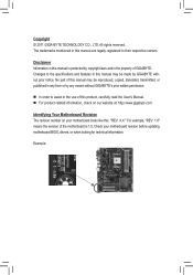
..., carefully read the User's Manual. For product-related information, check on our website at: http://www.gigabyte.com Identifying Your Motherboard Revision The revision number on your motherboard revision before updating motherboard BIOS, drivers, or when looking for technical information. Example: Changes to the specifications and features in this manual may...
..., carefully read the User's Manual. For product-related information, check on our website at: http://www.gigabyte.com Identifying Your Motherboard Revision The revision number on your motherboard revision before updating motherboard BIOS, drivers, or when looking for technical information. Example: Changes to the specifications and features in this manual may...
User Manual
Page 4
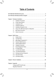
...GA-A75M-S2V Motherboard Layout 5 GA-A75M-S2V Motherboard Block Diagram 6 Chapter 1 Hardware Installation 7 1-1 Installation Precautions 7 1-2 Product Specifications 8 1-3 Installing the APU 11 1-4 Installing the Memory 12 1-5 Installing an Expansion Card 12 1-6 Setup of the AMD Dual Graphics Configuration 13 1-7 Back Panel Connectors 14 1-8 Internal Connectors 15 Chapter 2 BIOS... Setup 23 2-1 Startup Screen 23 2-2 The Main Menu 24 2-3 MB Intelligent Tweaker(M.I.T 25 2-4 Standard CMOS Features 29 2-5 Advanced BIOS Features 30 2-6 Integrated ...
...GA-A75M-S2V Motherboard Layout 5 GA-A75M-S2V Motherboard Block Diagram 6 Chapter 1 Hardware Installation 7 1-1 Installation Precautions 7 1-2 Product Specifications 8 1-3 Installing the APU 11 1-4 Installing the Memory 12 1-5 Installing an Expansion Card 12 1-6 Setup of the AMD Dual Graphics Configuration 13 1-7 Back Panel Connectors 14 1-8 Internal Connectors 15 Chapter 2 BIOS... Setup 23 2-1 Startup Screen 23 2-2 The Main Menu 24 2-3 MB Intelligent Tweaker(M.I.T 25 2-4 Standard CMOS Features 29 2-5 Advanced BIOS Features 30 2-6 Integrated ...
User Manual
Page 6
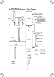
GA-A75M-S2V Motherboard Block Diagram 1 PCI Express x16 PCIe CLK (100 MHz) LAN 1 PCI Express x1 RJ45 Realtek RTL8111E x16 x1 x1 PCI Express Bus 1 PCI Express x4 AMD APU UMI APU CLK+/- (100 MHz) DISP CLK+/- (100 MHz) DDR3 2400(O.C.)/1866/ 1600/1333/1066 MHz Dual Channel Memory DVI-D PCIe CLK (100 MHz) x4 PCI Express Bus PCI Bus D-Sub 4 USB 3.0/2.0 AMD A75 CODEC 6 USB 2.0/1.1 Dual BIOS 6 SATA 6Gb/s LPC Bus iTE IT8720 COM Port PS/2 KB/Mouse 1 PCI PCI CLK (33 MHz) MIC (Center/Subwoofer Speaker Out) Line Out (Front Speaker Out) Line In (Rear Speaker Out) S/PDIF Out - 6 -
GA-A75M-S2V Motherboard Block Diagram 1 PCI Express x16 PCIe CLK (100 MHz) LAN 1 PCI Express x1 RJ45 Realtek RTL8111E x16 x1 x1 PCI Express Bus 1 PCI Express x4 AMD APU UMI APU CLK+/- (100 MHz) DISP CLK+/- (100 MHz) DDR3 2400(O.C.)/1866/ 1600/1333/1066 MHz Dual Channel Memory DVI-D PCIe CLK (100 MHz) x4 PCI Express Bus PCI Bus D-Sub 4 USB 3.0/2.0 AMD A75 CODEC 6 USB 2.0/1.1 Dual BIOS 6 SATA 6Gb/s LPC Bus iTE IT8720 COM Port PS/2 KB/Mouse 1 PCI PCI CLK (33 MHz) MIC (Center/Subwoofer Speaker Out) Line Out (Front Speaker Out) Line In (Rear Speaker Out) S/PDIF Out - 6 -
User Manual
Page 9
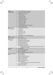
... APU/system cooler you install. BIOS ŠŠ 2 x 32 Mbit flash ŠŠ Use of licensed AWARD BIOS ŠŠ Support for DualBIOS™ ŠŠ PnP 1.0a, DMI 2.0, SM BIOS 2.4, ACPI 1.0b Unique Features ŠŠ Support for @BIOS ŠŠ Support for Q-...Flash ŠŠ Support for Xpress BIOS Rescue ŠŠ Support for Download Center...
... APU/system cooler you install. BIOS ŠŠ 2 x 32 Mbit flash ŠŠ Use of licensed AWARD BIOS ŠŠ Support for DualBIOS™ ŠŠ PnP 1.0a, DMI 2.0, SM BIOS 2.4, ACPI 1.0b Unique Features ŠŠ Support for @BIOS ŠŠ Support for Q-...Flash ŠŠ Support for Xpress BIOS Rescue ŠŠ Support for Download Center...
User Manual
Page 12
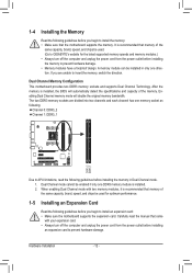
...to install the memory: • Make sure that memory of the same capacity, brand, speed, and chips be used . (Go to GIGABYTE's website for optimum performance. 1-5 Installing an Expansion Card Read the following guidelines before you are divided into two channels and each channel has ...one DDR3 memory module is installed, the BIOS will double the original memory bandwidth. Hardware Installation - 12 - Dual Channel mode cannot be installed in Dual Channel mode. 1. It is...
...to install the memory: • Make sure that memory of the same capacity, brand, speed, and chips be used . (Go to GIGABYTE's website for optimum performance. 1-5 Installing an Expansion Card Read the following guidelines before you are divided into two channels and each channel has ...one DDR3 memory module is installed, the BIOS will double the original memory bandwidth. Hardware Installation - 12 - Dual Channel mode cannot be installed in Dual Channel mode. 1. It is...
User Manual
Page 13
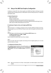
...Dual Graphics technology (for the Chipset, onboard graphics, and external graphics card are properly installed. - 13 - Step 2: Enter BIOS Setup to set the following instructions on the back panel and restart your computer. Power off your computer. Configuring the Graphics Driver...computer. Windows 7 operating system - Hardware Installation Save the settings and exit BIOS Setup. C. Browse to the AMD VISION Engine Control Center. AMD A series processor - Installing the Graphics Cards and Configuring BIOS Setup Step 1: Observe the steps in the operating system, go to ...
...Dual Graphics technology (for the Chipset, onboard graphics, and external graphics card are properly installed. - 13 - Step 2: Enter BIOS Setup to set the following instructions on the back panel and restart your computer. Power off your computer. Configuring the Graphics Driver...computer. Windows 7 operating system - Hardware Installation Save the settings and exit BIOS Setup. C. Browse to the AMD VISION Engine Control Center. AMD A series processor - Installing the Graphics Cards and Configuring BIOS Setup Step 1: Observe the steps in the operating system, go to ...
User Manual
Page 18
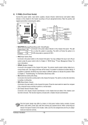
...is on the chassis to this header, make sure the wire assignments and the pin assignments are matched correctly. If a problem is detected, the BIOS may configure the way to turn off (S5). • PW (Power Switch, Red): Connects to the hard drive activity LED on the chassis... intrusion switch/sensor and system status indicator on when the system is operating. When connecting your system using the power switch (refer to Chapter 2, "BIOS Setup," "Power Management Setup," for information about beep codes. • HD (Hard Drive Activity LED, Blue) Connects to the power switch on the...
...is on the chassis to this header, make sure the wire assignments and the pin assignments are matched correctly. If a problem is detected, the BIOS may configure the way to turn off (S5). • PW (Power Switch, Red): Connects to the hard drive activity LED on the chassis... intrusion switch/sensor and system status indicator on when the system is operating. When connecting your system using the power switch (refer to Chapter 2, "BIOS Setup," "Power Management Setup," for information about beep codes. • HD (Hard Drive Activity LED, Blue) Connects to the power switch on the...
User Manual
Page 20
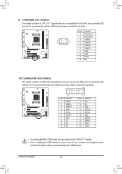
... UG bracket. Definition 1 VBUS 11 D2+ 2 SSRX1- 12 D2- 3 SSRX1+ 13 GND 4 GND 14 SSTX2+ 5 SSTX1- 15 SSTX2- 6 SSTX1+ 16 GND 7 GND 17 SSRX2+ DB_PORT BIOS 8 D1- 18 SSRX2- 9 D1+ 19 VBUS 10 NC 20 No Pin TPM w/housing Voltage measurement module(X58A-OC) PW •• Do not plug the...
... UG bracket. Definition 1 VBUS 11 D2+ 2 SSRX1- 12 D2- 3 SSRX1+ 13 GND 4 GND 14 SSTX2+ 5 SSTX1- 15 SSTX2- 6 SSTX1+ 16 GND 7 GND 17 SSRX2+ DB_PORT BIOS 8 D1- 18 SSRX2- 9 D1+ 19 VBUS 10 NC 20 No Pin TPM w/housing Voltage measurement module(X58A-OC) PW •• Do not plug the...
User Manual
Page 21
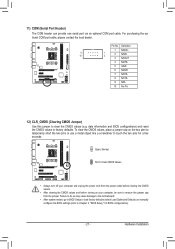
11) COM (Serial Port Header) The COM header can provide one serial port via an optional COM port cable. date information and BIOS configurations) and reset the CMOS values to clear the CMOS values (e.g. Hardware Installation Failure to do so may cause damage to the ...," for a few seconds. To clear the CMOS values, place a jumper cap on your computer, be sure to touch the two pins for BIOS configurations). - 21 - For purchasing the optional COM port cable, please contact the local dealer. Definition 1 NDCD- 9 10 1 2 2 NSIN 3 NSOUT 4 NDTR- 5 GND 6 NDSR- 7 NRTS- 8 ...
11) COM (Serial Port Header) The COM header can provide one serial port via an optional COM port cable. date information and BIOS configurations) and reset the CMOS values to clear the CMOS values (e.g. Hardware Installation Failure to do so may cause damage to the ...," for a few seconds. To clear the CMOS values, place a jumper cap on your computer, be sure to touch the two pins for BIOS configurations). - 21 - For purchasing the optional COM port cable, please contact the local dealer. Definition 1 NDCD- 9 10 1 2 2 NSIN 3 NSOUT 4 NDTR- 5 GND 6 NDSR- 7 NRTS- 8 ...
User Manual
Page 22
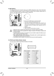
... able to replace the battery by removing the battery: 1. 13) BAT (Battery) The battery provides power to keep the values (such as BIOS configurations, date, and time information) in the power cord and restart your computer. • Always turn off your computer and unplug the power..., note the orientation of the positive side (+) and the negative side (-) of the battery holder, making them short for 5 seconds.) 3F._URSeBp3l0ace the battery. DB_PORT BIOS Switc 1 1 19 TPM w/housing 20 Pin No. 1 2 3 4 5 6 7 8 9 10 Definition LCLK GND LFRAME No Pin LRESET NC LAD3 LAD2 VCC3 LAD1 1 ...
... able to replace the battery by removing the battery: 1. 13) BAT (Battery) The battery provides power to keep the values (such as BIOS configurations, date, and time information) in the power cord and restart your computer. • Always turn off your computer and unplug the power..., note the orientation of the positive side (+) and the negative side (-) of the battery holder, making them short for 5 seconds.) 3F._URSeBp3l0ace the battery. DB_PORT BIOS Switc 1 1 19 TPM w/housing 20 Pin No. 1 2 3 4 5 6 7 8 9 10 Definition LCLK GND LFRAME No Pin LRESET NC LAD3 LAD2 VCC3 LAD1 1 ...
User Manual
Page 23
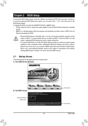
... unexpected results. Inadequately altering the settings may appear when the computer boots. A. GA-A75M-S2V F1e . . . . : BIOS Setup : XpressRecovery2 : Boot Menu : Qflash 06/07/2011-Llano-Hudson-7A66HG05C-00 Function Keys Function Keys - 23 - BIOS Setup To upgrade the BIOS, use either the GIGABYTE Q-Flash or @BIOS utility. •• Q-Flash allows the user to clear the CMOS...
... unexpected results. Inadequately altering the settings may appear when the computer boots. A. GA-A75M-S2V F1e . . . . : BIOS Setup : XpressRecovery2 : Boot Menu : Qflash 06/07/2011-Llano-Hudson-7A66HG05C-00 Function Keys Function Keys - 23 - BIOS Setup To upgrade the BIOS, use either the GIGABYTE Q-Flash or @BIOS utility. •• Q-Flash allows the user to clear the CMOS...
User Manual
Page 24
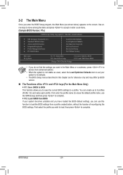
... a profile created before, without the hassles of the and keys (For the Main Menu Only) F11: Save CMOS to BIOS This function allows you to save the current BIOS settings to a profile. First select the profile you can create up to 8 profiles (Profile 1-8) and name each profile. Use arrow...Menu or a submenu, press + to access more advanced options. •• When the system is not stable as shown below) appears on the screen. BIOS Setup - 24 - First enter the profile name (to erase the default profile name, use this chapter are for reference only and may differ by...
... a profile created before, without the hassles of the and keys (For the Main Menu Only) F11: Save CMOS to BIOS This function allows you to save the current BIOS settings to a profile. First select the profile you can create up to 8 profiles (Profile 1-8) and name each profile. Use arrow...Menu or a submenu, press + to access more advanced options. •• When the system is not stable as shown below) appears on the screen. BIOS Setup - 24 - First enter the profile name (to erase the default profile name, use this chapter are for reference only and may differ by...
User Manual
Page 25
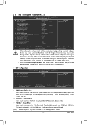
... of these components. 2-3 MB Intelligent Tweaker(M.I.T.) CMOS Setup Utility-Copyright (C) 1984-2011 Award Software MB Intelligent Tweaker(M.I.T.) } IGX Configuration CPU Clock Ratio CPU NorthBridge Freq. BIOS Setup If this feature. - 25 - IGX Configuration CMOS Setup Utility-Copyright (C) 1984-2011 Award Software IGX Configuration UMA Frame Buffer Size VGA Core Clock control...
... of these components. 2-3 MB Intelligent Tweaker(M.I.T.) CMOS Setup Utility-Copyright (C) 1984-2011 Award Software MB Intelligent Tweaker(M.I.T.) } IGX Configuration CPU Clock Ratio CPU NorthBridge Freq. BIOS Setup If this feature. - 25 - IGX Configuration CMOS Setup Utility-Copyright (C) 1984-2011 Award Software IGX Configuration UMA Frame Buffer Size VGA Core Clock control...
User Manual
Page 26
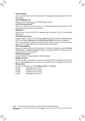
Allows you to manually set in accordance with the CPU specifications. Auto (default) allows the BIOS to X5.33. CPU Frequency(MHz) Allows you to X9.33. (Note) This item is highly recommended that supports this feature. Important It is present ....33 Sets Memory Clock to automatically adjust the CPU host frequency. This option is configurable only when CPU Host Clock Control is set to Manual. BIOS Setup - 26 - Manual allows the CPU Frequency (MHz) item below to be configurable. PCIe Spread Spectrum Enables or disables PCIe Spread Spectrum. (Default: Disabled) Set...
Allows you to manually set in accordance with the CPU specifications. Auto (default) allows the BIOS to X5.33. CPU Frequency(MHz) Allows you to X9.33. (Note) This item is highly recommended that supports this feature. Important It is present ....33 Sets Memory Clock to automatically adjust the CPU host frequency. This option is configurable only when CPU Host Clock Control is set to Manual. BIOS Setup - 26 - Manual allows the CPU Frequency (MHz) item below to be configurable. PCIe Spread Spectrum Enables or disables PCIe Spread Spectrum. (Default: Disabled) Set...
User Manual
Page 27
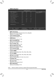
... [Auto] Auto Auto Auto Auto Auto Auto Auto Auto Auto Auto Auto Auto Auto SPD -9T 9T 9T 24T 5T -110ns 10T 5T 33T 4T -- BIOS Setup DRAM Configuration CMOS Setup Utility-Copyright (C) 1984-2011 Award Software DRAM Configuration DDR3 Timing Items x 1T/2T Command Timing x CAS# latency x RAS to CAS...
... [Auto] Auto Auto Auto Auto Auto Auto Auto Auto Auto Auto Auto Auto Auto SPD -9T 9T 9T 24T 5T -110ns 10T 5T 33T 4T -- BIOS Setup DRAM Configuration CMOS Setup Utility-Copyright (C) 1984-2011 Award Software DRAM Configuration DDR3 Timing Items x 1T/2T Command Timing x CAS# latency x RAS to CAS...

User Manual
Page 28
Bank Interleaving Enables or disables memory bank interleaving. CPU VDDP Voltage Control Allows you to set the CPU voltage. BIOS Setup - 28 - CPU VCORE Control Allows you to set the system voltages as required. (Default) -0.600V ~ +0.600V The adjustable range is from... -0.600V to the memory or reduce the useful life of the memory. Auto lets the BIOS automatically set the CPU NorthBridge VID voltage. FCH Voltage Control Allows you to set the system voltages. Normal Supplies the Chipset voltage as required. (...
Bank Interleaving Enables or disables memory bank interleaving. CPU VDDP Voltage Control Allows you to set the CPU voltage. BIOS Setup - 28 - CPU VCORE Control Allows you to set the system voltages as required. (Default) -0.600V ~ +0.600V The adjustable range is from... -0.600V to the memory or reduce the useful life of the memory. Auto lets the BIOS automatically set the CPU NorthBridge VID voltage. FCH Voltage Control Allows you to set the system voltages. Normal Supplies the Chipset voltage as required. (...
User Manual
Page 29
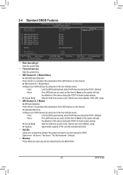
... Defaults ESC: Exit F1: General Help F7: Optimized Defaults Date (mm:dd:yy) Sets the system date. BIOS Setup IDE Channel 0, 1 Master/Slave Configure your SATA devices by the BIOS POST. - 29 - Access Mode Sets the hard drive access mode. IDE Channel 0, 1 Master/Slave IDE HDD... Auto-Detection Press to autodetect the parameters of the two methods below : • Auto Lets the BIOS automatically detect SATA devices during the POST. (Default) • None If no SATA devices are used , set this item to determine whether the...
... Defaults ESC: Exit F1: General Help F7: Optimized Defaults Date (mm:dd:yy) Sets the system date. BIOS Setup IDE Channel 0, 1 Master/Slave Configure your SATA devices by the BIOS POST. - 29 - Access Mode Sets the hard drive access mode. IDE Channel 0, 1 Master/Slave IDE HDD... Auto-Detection Press to autodetect the parameters of the two methods below : • Auto Lets the BIOS automatically detect SATA devices during the POST. (Default) • None If no SATA devices are used , set this item to determine whether the...
User Manual
Page 30
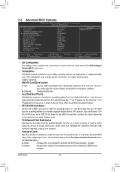
... to be installed supports booting from the available devices. Auto lets the BIOS automatically configure this function. BIOS Setup - 30 - 2-5 Advanced BIOS Features CMOS Setup Utility-Copyright (C) 1984-2011 Award Software Advanced BIOS Features } IGX Configuration Virtualization AMD K8 Cool&Quiet control } Hard Disk...a password is required for booting the system and for entering the BIOS Setup program. (Default) System A password is required every time the system boots, or only when you enter BIOS Setup. Hard Disk Boot Priority Specifies the sequence of loading the operating...
... to be installed supports booting from the available devices. Auto lets the BIOS automatically configure this function. BIOS Setup - 30 - 2-5 Advanced BIOS Features CMOS Setup Utility-Copyright (C) 1984-2011 Award Software Advanced BIOS Features } IGX Configuration Virtualization AMD K8 Cool&Quiet control } Hard Disk...a password is required for booting the system and for entering the BIOS Setup program. (Default) System A password is required every time the system boots, or only when you enter BIOS Setup. Hard Disk Boot Priority Specifies the sequence of loading the operating...
User Manual
Page 31
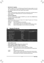
... SATA controller to operate in Native IDE mode. (Default) Enable Native IDE mode if you to determine whether to display the GIGABYTE Logo at system startup. PEG Sets the PCI Express graphics card on the PCIEX16 slot as the first display. (Default) PEG1...the integrated SATA controllers. (Default: Enabled) OnChip SATA Type (SATA3_0~SATA3_3 connectors) Configures the operating mode of the SATA3_0~SATA3_3 connectors. BIOS Setup HDD S.M.A.R.T. Capability Enables or disables the S.M.A.R.T. (Self Monitoring and Reporting Technology) capability of your system to report read/write errors...
... SATA controller to operate in Native IDE mode. (Default) Enable Native IDE mode if you to determine whether to display the GIGABYTE Logo at system startup. PEG Sets the PCI Express graphics card on the PCIEX16 slot as the first display. (Default) PEG1...the integrated SATA controllers. (Default: Enabled) OnChip SATA Type (SATA3_0~SATA3_3 connectors) Configures the operating mode of the SATA3_0~SATA3_3 connectors. BIOS Setup HDD S.M.A.R.T. Capability Enables or disables the S.M.A.R.T. (Self Monitoring and Reporting Technology) capability of your system to report read/write errors...
User Manual
Page 32
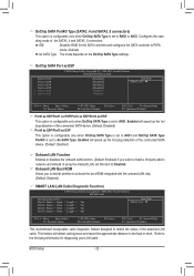
... SATA3_4 and SATA3_5 connectors. IDE Disables RAID for the SATA controller and configures the SATA controller to the following information for diagnosing your LAN cable: BIOS Setup - 32 - OnChip SATA Port as ESP Port0 as ESP Port1 as ESP Port2 as ESP Port3 as ESP x Port4 as ESP x Port5 as ESP...
... SATA3_4 and SATA3_5 connectors. IDE Disables RAID for the SATA controller and configures the SATA controller to the following information for diagnosing your LAN cable: BIOS Setup - 32 - OnChip SATA Port as ESP Port0 as ESP Port1 as ESP Port2 as ESP Port3 as ESP x Port4 as ESP x Port5 as ESP...


