User Manual
Page 2
Motherboard GA-A55M-S2V Jun. 28, 2011 Motherboard GA-A55M-S2V Jun. 28, 2011
Motherboard GA-A55M-S2V Jun. 28, 2011 Motherboard GA-A55M-S2V Jun. 28, 2011
User Manual
Page 3
... or published in any form or by any means without prior notice. For example, "REV: 1.0" means the revision of GIGABYTE. No part of this manual are legally registered to their respective owners. Changes to the specifications and features in this manual is ... the User's Manual. For product-related information, check on our website at: http://www.gigabyte.com Identifying Your Motherboard Revision The revision number on your motherboard revision before updating motherboard BIOS, drivers, or when looking for technical information. Copyright © 2011 GIGA-BYTE TECHNOLOGY CO.,...
... or published in any form or by any means without prior notice. For example, "REV: 1.0" means the revision of GIGABYTE. No part of this manual are legally registered to their respective owners. Changes to the specifications and features in this manual is ... the User's Manual. For product-related information, check on our website at: http://www.gigabyte.com Identifying Your Motherboard Revision The revision number on your motherboard revision before updating motherboard BIOS, drivers, or when looking for technical information. Copyright © 2011 GIGA-BYTE TECHNOLOGY CO.,...
User Manual
Page 4
Table of Contents GA-A55M-S2V Motherboard Layout 5 GA-A55M-S2V Motherboard Block Diagram 6 Chapter 1 Hardware Installation 7 1-1 Installation Precautions 7 1-2 Product Specifications 8 1-3 Installing the APU and APU Cooler 10 1-4 Installing the Memory 11 1-5 Installing an Expansion Card 11 1-6 ...
Table of Contents GA-A55M-S2V Motherboard Layout 5 GA-A55M-S2V Motherboard Block Diagram 6 Chapter 1 Hardware Installation 7 1-1 Installation Precautions 7 1-2 Product Specifications 8 1-3 Installing the APU and APU Cooler 10 1-4 Installing the Memory 11 1-5 Installing an Expansion Card 11 1-6 ...
User Manual
Page 5
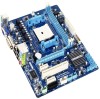
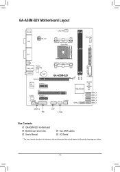
GA-A55M-S2V Motherboard Layout KB_MS VGA ATX_12V CPU_FAN Socket FM1 SYS_FAN ATX DVI R_USB USB_LAN Realtek RTL8111E AUDIO BAT PCIEX16 iTE IT8720 PCIEX1_1 PCI CODEC PCIEX1_2 F_AUDIO SPDIF_O TPM GA-A55M-S2V F_USB1 COM F_USB2 F_PANEL M_BIOS AMD A75/A55 SATA2_0 B_BIOS SATA2_5 SATA2_4 SATA2_3 SATA2_2 SATA2_1 DDR3_2 DDR3_1 CLR_CMOS Box Contents GA-A55M-S2V motherboard Motherboard driver disk User's Manual Two SATA cables I/O Shield * The box contents above are for reference only and the actual items shall depend on the product package you obtain. - 5 -
GA-A55M-S2V Motherboard Layout KB_MS VGA ATX_12V CPU_FAN Socket FM1 SYS_FAN ATX DVI R_USB USB_LAN Realtek RTL8111E AUDIO BAT PCIEX16 iTE IT8720 PCIEX1_1 PCI CODEC PCIEX1_2 F_AUDIO SPDIF_O TPM GA-A55M-S2V F_USB1 COM F_USB2 F_PANEL M_BIOS AMD A75/A55 SATA2_0 B_BIOS SATA2_5 SATA2_4 SATA2_3 SATA2_2 SATA2_1 DDR3_2 DDR3_1 CLR_CMOS Box Contents GA-A55M-S2V motherboard Motherboard driver disk User's Manual Two SATA cables I/O Shield * The box contents above are for reference only and the actual items shall depend on the product package you obtain. - 5 -
User Manual
Page 6
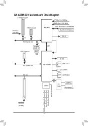
GA-A55M-S2V Motherboard Block Diagram 1 PCI Express x16 APU CLK+/- (100 MHz) DISP CLK+/- (100 MHz) PCIe CLK (100 MHz) 1 PCI Express x1 AMD APU DDR3 1866/1600/1333/1066 MHz Dual Channel Memory x16 x1 DVI-D PCI Express Bus x1 Realtek UMI RTL8111E 1 PCI Express x1 RJ45 LAN x1 PCI Express Bus AMD A75/A55 D-Sub 8 USB 2.0/1.1 Dual BIOS PCI Bus CODEC 6 SATA 3Gb/s LPC Bus iTE IT8720 COM Port PS/2 KB/Mouse MIC (Center/Subwoofer Speaker Out) Line Out (Front Speaker Out) Line In (Rear Speaker Out) S/PDIF Out 1 PCI PCI CLK (33 MHz) - 6 -
GA-A55M-S2V Motherboard Block Diagram 1 PCI Express x16 APU CLK+/- (100 MHz) DISP CLK+/- (100 MHz) PCIe CLK (100 MHz) 1 PCI Express x1 AMD APU DDR3 1866/1600/1333/1066 MHz Dual Channel Memory x16 x1 DVI-D PCI Express Bus x1 Realtek UMI RTL8111E 1 PCI Express x1 RJ45 LAN x1 PCI Express Bus AMD A75/A55 D-Sub 8 USB 2.0/1.1 Dual BIOS PCI Bus CODEC 6 SATA 3Gb/s LPC Bus iTE IT8720 COM Port PS/2 KB/Mouse MIC (Center/Subwoofer Speaker Out) Line Out (Front Speaker Out) Line In (Rear Speaker Out) S/PDIF Out 1 PCI PCI CLK (33 MHz) - 6 -

User Manual
Page 7
...supply has been turned off. •• Before turning on the computer power during the installation process can become damaged as a motherboard, APU or memory. ponents such as a result of electrostatic discharge (ESD). Prior to installation, carefully read the user's manual... power connectors of the product, please consult a certified computer technician. - 7 - Chapter 1 Hardware Installation 1-1 Installation Precautions The motherboard contains numerous delicate electronic circuits and components which can lead to damage to system components as well as physical harm to the user....
...supply has been turned off. •• Before turning on the computer power during the installation process can become damaged as a motherboard, APU or memory. ponents such as a result of electrostatic discharge (ESD). Prior to installation, carefully read the user's manual... power connectors of the product, please consult a certified computer technician. - 7 - Chapter 1 Hardware Installation 1-1 Installation Precautions The motherboard contains numerous delicate electronic circuits and components which can lead to damage to system components as well as physical harm to the user....

User Manual
Page 9
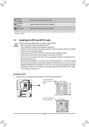
... Center ŠŠ Support for Xpress Install ŠŠ Support for Xpress Recovery2 ŠŠ Support for EasyTune * Available functions in EasyTune may differ by motherboard model. ŠŠ Support for Smart Recovery ŠŠ Support for Auto Green ŠŠ Support for ON/OFF Charge ŠŠ Support for 3TB...
... Center ŠŠ Support for Xpress Install ŠŠ Support for Xpress Recovery2 ŠŠ Support for EasyTune * Available functions in EasyTune may differ by motherboard model. ŠŠ Support for Smart Recovery ŠŠ Support for Auto Green ŠŠ Support for ON/OFF Charge ŠŠ Support for 3TB...
User Manual
Page 10
... if oriented incorrectly. • Apply an even and thin layer of thermal grease on the computer if the APU cooler is not recommended that the motherboard supports the APU. (Go to prevent hardware damage. • Locate the pin one (denoted by a small triangle) of the APU socket and the APU...of the APU. • Do not turn off the computer and unplug the power cord from the power outlet before installing the APU to GIGABYTE's website for the peripherals. The APU cannot be set the frequency beyond hardware specifications since it does not meet the standard requirements for the ...
... if oriented incorrectly. • Apply an even and thin layer of thermal grease on the computer if the APU cooler is not recommended that the motherboard supports the APU. (Go to prevent hardware damage. • Locate the pin one (denoted by a small triangle) of the APU socket and the APU...of the APU. • Do not turn off the computer and unplug the power cord from the power outlet before installing the APU to GIGABYTE's website for the peripherals. The APU cannot be set the frequency beyond hardware specifications since it does not meet the standard requirements for the ...

User Manual
Page 11
... switch the direction. After the memory is installed, the BIOS will double the original memory bandwidth. Dual Channel Memory Configuration This motherboard provides two DDR3 memory sockets and supports Dual Channel Technology. DDR3_2 DDR3_1 It is recommended that memory of the same capacity, brand...same capacity, brand, speed, and chips be installed in Dual Channel mode. 111 Dual Channel mode cannot be used . (Go to GIGABYTE's website for optimum performance. 1-5 Installing an Expansion Card Read the following guidelines before you begin to install an expansion card: •...
... switch the direction. After the memory is installed, the BIOS will double the original memory bandwidth. Dual Channel Memory Configuration This motherboard provides two DDR3 memory sockets and supports Dual Channel Technology. DDR3_2 DDR3_1 It is recommended that memory of the same capacity, brand...same capacity, brand, speed, and chips be installed in Dual Channel mode. 111 Dual Channel mode cannot be used . (Go to GIGABYTE's website for optimum performance. 1-5 Installing an Expansion Card Read the following guidelines before you begin to install an expansion card: •...

User Manual
Page 12
... properly installed. - 12 - Plug the monitor cable into the integrated graphics port on the PCIEX16 slot. C. Windows 7 operating system - An AMD Dual Graphics technology-supported motherboard and correct driver - Configuring the Graphics Driver After installing the graphics card driver in "1-5 Installing an Expansion Card" and install an AMD Dual Graphics technologysupported...
... properly installed. - 12 - Plug the monitor cable into the integrated graphics port on the PCIEX16 slot. C. Windows 7 operating system - An AMD Dual Graphics technology-supported motherboard and correct driver - Configuring the Graphics Driver After installing the graphics card driver in "1-5 Installing an Expansion Card" and install an AMD Dual Graphics technologysupported...

User Manual
Page 13
... as an optical drive, walkman, etc. Mic In Jack (Pink) The default Mic in a 4/5.1/7.1-channel audio configuration. Do not rock it straight out from the motherboard. •• When removing the cable, pull it side to side to connect front speakers in jack. If you have to use an HD front...
... as an optical drive, walkman, etc. Mic In Jack (Pink) The default Mic in a 4/5.1/7.1-channel audio configuration. Do not rock it straight out from the motherboard. •• When removing the cable, pull it side to side to connect front speakers in jack. If you have to use an HD front...

User Manual
Page 14
... sure your devices are compliant with the connectors you wish to connect. •• Before installing the devices, be sure to the connector on the motherboard. - 14 - Unplug the power cord from the power outlet to prevent damage to the devices. •• After installing the device and before connecting external...
... sure your devices are compliant with the connectors you wish to connect. •• Before installing the devices, be sure to the connector on the motherboard. - 14 - Unplug the power cord from the power outlet to prevent damage to the devices. •• After installing the device and before connecting external...

User Manual
Page 15
... power connector, first make sure the power supply is used (500W or greater). If a power supply is turned off and all the components on the motherboard. The 12V power connector mainly supplies power to the power connector in the correct orientation. The power connector possesses a foolproof design. To meet expansion requirements...
... power connector, first make sure the power supply is used (500W or greater). If a power supply is turned off and all the components on the motherboard. The 12V power connector mainly supplies power to the power connector in the correct orientation. The power connector possesses a foolproof design. To meet expansion requirements...
User Manual
Page 16
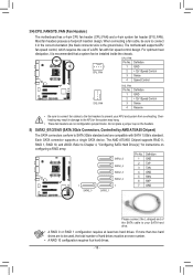
... SATA2_1 Please connect the L-shaped end of a APU fan with SATA 1.5Gb/s standard. 3/4) CPU_FAN/SYS_FAN (Fan Headers) The motherboard has a 4-pin CPU fan header (CPU_FAN) and a 4-pin system fan header (SYS_FAN). The motherboard supports APU fan speed control, which requires the use of the SATA cable to Chapter 4, "Configuring SATA Hard Drive...
... SATA2_1 Please connect the L-shaped end of a APU fan with SATA 1.5Gb/s standard. 3/4) CPU_FAN/SYS_FAN (Fan Headers) The motherboard has a 4-pin CPU fan header (CPU_FAN) and a 4-pin system fan header (SYS_FAN). The motherboard supports APU fan speed control, which requires the use of the SATA cable to Chapter 4, "Configuring SATA Hard Drive...

User Manual
Page 18
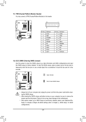
...10 NC DB_PORT•• The front panel audio heBaIdOeSrSswuitpchpeor r(Xts58HA-DOCa)udio by expansion cards) for digital audio output from your motherboard to your chassis front panel audio module to this header. 7) F_AUDIO (Front Panel Audio Header) The front panel audio header ...single plug. Pin No. You may require you to use a S/PDIF digital audio cable for digital audio output from 1y2o3ur motherboard to certain expansion cards like graphics cards aPnCdIespoouwnerdcocnanredcsto.r F(SoArTAe)x(Xa5m8Ap-OleC,)some graphics cards may connect your graphics card if you ...
...10 NC DB_PORT•• The front panel audio heBaIdOeSrSswuitpchpeor r(Xts58HA-DOCa)udio by expansion cards) for digital audio output from your motherboard to your chassis front panel audio module to this header. 7) F_AUDIO (Front Panel Audio Header) The front panel audio header ...single plug. Pin No. You may require you to use a S/PDIF digital audio cable for digital audio output from 1y2o3ur motherboard to certain expansion cards like graphics cards aPnCdIespoouwnerdcocnanredcsto.r F(SoArTAe)x(Xa5m8Ap-OleC,)some graphics cards may connect your graphics card if you ...
User Manual
Page 20
... CMOS values, place a jumper cap on your computer, be sure to factory defaults. 11) TPM (Trusted Platform Module Header) You may cause damage to the motherboard. •• After system restart, go to BIOS Setup to load factory defaults (select Load Optimized Defaults) or manually configure the BIOS settings (refer to...
... CMOS values, place a jumper cap on your computer, be sure to factory defaults. 11) TPM (Trusted Platform Module Header) You may cause damage to the motherboard. •• After system restart, go to BIOS Setup to load factory defaults (select Load Optimized Defaults) or manually configure the BIOS settings (refer to...
User Manual
Page 22
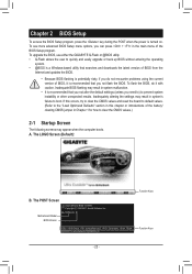
... do not encounter problems using the current version of the battery/ clearing CMOS jumper in system's failure to prevent system instability or other unexpected results. GA-A55M-S2V E1 . . . . : BIOS Setup : XpressRecovery2 : Boot Menu : Qflash 06/09/2011-Llano-Hudson-7A66HG09C-00 Function Keys Function Keys -... chapter or introductions of BIOS, it with caution. The POST Screen Motherboard Model BIOS Version Award Modular BIOS v6.00PG Copyright (C) 1984-2011, Award Software, Inc. To upgrade the BIOS, use either the GIGABYTE Q-Flash or @BIOS utility. •• Q-Flash allows the ...
... do not encounter problems using the current version of the battery/ clearing CMOS jumper in system's failure to prevent system instability or other unexpected results. GA-A55M-S2V E1 . . . . : BIOS Setup : XpressRecovery2 : Boot Menu : Qflash 06/09/2011-Llano-Hudson-7A66HG09C-00 Function Keys Function Keys -... chapter or introductions of BIOS, it with caution. The POST Screen Motherboard Model BIOS Version Award Modular BIOS v6.00PG Copyright (C) 1984-2011, Award Software, Inc. To upgrade the BIOS, use either the GIGABYTE Q-Flash or @BIOS utility. •• Q-Flash allows the ...
User Manual
Page 31
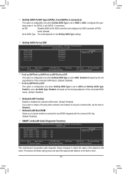
...; Move Enter: Select F5: Previous Values +/-/PU/PD: Value F10: Save F6: Fail-Safe Defaults ESC: Exit F1: General Help F7: Optimized Defaults This motherboard incorporates cable diagnostic feature designed to activate the boot ROM integrated with the onboard LAN chip. (Default: Disabled) SMART LAN (LAN Cable Diagnostic Function) CMOS...
...; Move Enter: Select F5: Previous Values +/-/PU/PD: Value F10: Save F6: Fail-Safe Defaults ESC: Exit F1: General Help F7: Optimized Defaults This motherboard incorporates cable diagnostic feature designed to activate the boot ROM integrated with the onboard LAN chip. (Default: Disabled) SMART LAN (LAN Cable Diagnostic Function) CMOS...

User Manual
Page 34
... for CPU temperature. Current CPU/SYSTEM FAN Speed (RPM) Displays current CPU/system fan speed. CPU/SYSTEM FAN Fail Warning Allows the system to the motherboard CI header. Enabled allows the CPU fan to run at full speed. (Default: Enabled) - 34 - You can adjust the fan speed with EasyTune based on...
... for CPU temperature. Current CPU/SYSTEM FAN Speed (RPM) Displays current CPU/system fan speed. CPU/SYSTEM FAN Fail Warning Allows the system to the motherboard CI header. Enabled allows the CPU fan to run at full speed. (Default: Enabled) - 34 - You can adjust the fan speed with EasyTune based on...
User Manual
Page 35
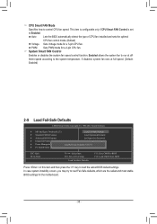
... load the safest BIOS default settings. System Smart FAN Control Enables or disables the system fan speed control function. PWM Sets PWM mode for the motherboard. - 35 - ENxit Setup Exit Without Saving ESC: Quit F8: Q-Flash Select Item F10: Save & Exit Setup Load Fail-Safe Defaults F11: Save CMOS to BIOS...
... load the safest BIOS default settings. System Smart FAN Control Enables or disables the system fan speed control function. PWM Sets PWM mode for the motherboard. - 35 - ENxit Setup Exit Without Saving ESC: Quit F8: Q-Flash Select Item F10: Save & Exit Setup Load Fail-Safe Defaults F11: Save CMOS to BIOS...


