
Manual
Page 3
...Documentation Classifications In order to their respective owners. For product-related information, check on our website at: http://www.gigabyte.com Identifying Your Motherboard Revision The revision number on your motherboard revision before updating motherboard BIOS, drivers, or when... User's Manual. The trademarks mentioned in this manual are legally registered to assist in this product, GIGABYTE provides the following types of documentations: For quick set-up of this manual is protected by GIGABYTE without GIGABYTE's prior written permission. No part of GIGABYTE. For ...
...Documentation Classifications In order to their respective owners. For product-related information, check on our website at: http://www.gigabyte.com Identifying Your Motherboard Revision The revision number on your motherboard revision before updating motherboard BIOS, drivers, or when... User's Manual. The trademarks mentioned in this manual are legally registered to assist in this product, GIGABYTE provides the following types of documentations: For quick set-up of this manual is protected by GIGABYTE without GIGABYTE's prior written permission. No part of GIGABYTE. For ...

Manual
Page 5
Chapter 3 Drivers Installation 61 3-1 Installing Chipset Drivers 61 3-2 Application Software 62 3-3 Technical Manuals 62 3-4 Contact...63 3-5 System...63 3-6 Download Center 64 3-7 New Utilities...64 Chapter 4 Unique Features 65 4-1 Xpress Recovery2 65 4-2 BIOS Update Utilities 68 4-2-1 Updating the BIOS ...
Chapter 3 Drivers Installation 61 3-1 Installing Chipset Drivers 61 3-2 Application Software 62 3-3 Technical Manuals 62 3-4 Contact...63 3-5 System...63 3-6 Download Center 64 3-7 New Utilities...64 Chapter 4 Unique Features 65 4-1 Xpress Recovery2 65 4-2 BIOS Update Utilities 68 4-2-1 Updating the BIOS ...
Manual
Page 6
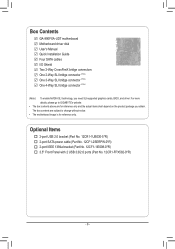
...GIGABYTE's website. • The box contents above are subject to change without notice. • The motherboard image is for reference only and the actual items shall depend on the product package you need SLI-supported graphics cards, BIOS, and driver. The box contents are for reference only. Box Contents GA-990FXA-UD7... motherboard Motherboard driver disk User's Manual Quick Installation Guide Four SATA cables I/O Shield Two 2-Way CrossFireX bridge connectors One 2-Way SLI ...
...GIGABYTE's website. • The box contents above are subject to change without notice. • The motherboard image is for reference only and the actual items shall depend on the product package you need SLI-supported graphics cards, BIOS, and driver. The box contents are for reference only. Box Contents GA-990FXA-UD7... motherboard Motherboard driver disk User's Manual Quick Installation Guide Four SATA cables I/O Shield Two 2-Way CrossFireX bridge connectors One 2-Way SLI ...

Manual
Page 9
... process can become damaged as a result of your dealer. Hardware Installation ponents such as a motherboard, CPU or memory. Prior to installation, carefully read the user's manual and follow these procedures: • Prior to installation, do not remove or break motherboard S/N (Serial Number) sticker or warranty sticker provided by unplugging the power...
... process can become damaged as a result of your dealer. Hardware Installation ponents such as a motherboard, CPU or memory. Prior to installation, carefully read the user's manual and follow these procedures: • Prior to installation, do not remove or break motherboard S/N (Serial Number) sticker or warranty sticker provided by unplugging the power...

Manual
Page 15
... the steps below to correctly install the CPU cooler on the CPU. (The following procedure uses the GIGABYTE cooler as the picture above shows) to lock into place. (Refer to your CPU cooler installation manual for instructions on installing the cooler.) Step 5: Finally, attach the power connector of the CPU cooler to...
... the steps below to correctly install the CPU cooler on the CPU. (The following procedure uses the GIGABYTE cooler as the picture above shows) to lock into place. (Refer to your CPU cooler installation manual for instructions on installing the cooler.) Step 5: Finally, attach the power connector of the CPU cooler to...

Manual
Page 18
...(s). 7. Install the driver provided with a screw. 5. Make sure the card is fully inserted into the slot. 4. Align the card with your card. Carefully read the manual that supports your expansion card. • Always turn off the computer and unplug the power cord from the chassis back panel. 2. Hardware Installation - 18 - •...
...(s). 7. Install the driver provided with a screw. 5. Make sure the card is fully inserted into the slot. 4. Align the card with your card. Carefully read the manual that supports your expansion card. • Always turn off the computer and unplug the power cord from the chassis back panel. 2. Hardware Installation - 18 - •...

Manual
Page 19
...the PCI Express x16 slots. Browse to Performance\AMD CrossFireX Configurations and ensure the Enable CrossFireX™ check box is recommended (refer to the manual of your graphics cards for more graphics cards are to ensure system stability. CrossFire bridge connectors (Note 1) - The following table shows the ... technology may be installed, we recommend that came with two/three/four PCI Express x16 slots and correct driver - Refer to the manual that you connect the SATA power cable from the power supply to the ATX4P connector to be needed or not depending on the number...
...the PCI Express x16 slots. Browse to Performance\AMD CrossFireX Configurations and ensure the Enable CrossFireX™ check box is recommended (refer to the manual of your graphics cards for more graphics cards are to ensure system stability. CrossFire bridge connectors (Note 1) - The following table shows the ... technology may be installed, we recommend that came with two/three/four PCI Express x16 slots and correct driver - Refer to the manual that you connect the SATA power cable from the power supply to the ATX4P connector to be needed or not depending on the number...

Manual
Page 22
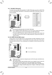
... the power outlet before clearing the CMOS values. • After system restart, go to BIOS Setup to load factory defaults (select Load Optimized Defaults) or manually configure the BIOS settings (refer to change hardware components or conduct hardware testing. Use the clearing CMOS button to factory defaults when needed. Hardware Installation...
... the power outlet before clearing the CMOS values. • After system restart, go to BIOS Setup to load factory defaults (select Load Optimized Defaults) or manually configure the BIOS settings (refer to change hardware components or conduct hardware testing. Use the clearing CMOS button to factory defaults when needed. Hardware Installation...

Manual
Page 28
...(Xio58mA-oOdCu) le that has different wire assignments, please contact the chassis manufacturer. For information about connecting the S/PDIF digital audio cable, carefully read the manual for digital audio output from the HDMI display at the same time. Pin No. Make sure the wire assignments of the module connector match the...
...(Xio58mA-oOdCu) le that has different wire assignments, please contact the chassis manufacturer. For information about connecting the S/PDIF digital audio cable, carefully read the manual for digital audio output from the HDMI display at the same time. Pin No. Make sure the wire assignments of the module connector match the...
Manual
Page 30
... so may cause damage to the motherboard. •• After system restart, go to BIOS Setup to load factory defaults (select Load Optimized Defaults) or manually configure the BIOS settings (refer to factory defaults. date information and BIOS configurations) and reset the CMOS values to Chapter 2, "BIOS Setup," for a few seconds...
... so may cause damage to the motherboard. •• After system restart, go to BIOS Setup to load factory defaults (select Load Optimized Defaults) or manually configure the BIOS settings (refer to factory defaults. date information and BIOS configurations) and reset the CMOS values to Chapter 2, "BIOS Setup," for a few seconds...

Manual
Page 38
...HT Link Frequency. (Default) x1~x10 Sets HT Link Frequency to x1~x10 (200 MHz~2.0 GHz). Set Memory Clock Determines whether to manually set in accordance with the CPU specifications. Auto lets BIOS automatically set the frequency for the HT Link between the CPU and chipset. CPU... whether to enable the Core Performance Boost (CPB) technology, a CPU performance-boost technology. (Default: Enabled) CPB Ratio (Note) Allows you to manually set to 150 MHz. The adjustable range is dependent on the CPU being used . This option is configurable only when CPU Host Clock Control is...
...HT Link Frequency. (Default) x1~x10 Sets HT Link Frequency to x1~x10 (200 MHz~2.0 GHz). Set Memory Clock Determines whether to manually set in accordance with the CPU specifications. Auto lets BIOS automatically set the frequency for the HT Link between the CPU and chipset. CPU... whether to enable the Core Performance Boost (CPB) technology, a CPU performance-boost technology. (Default: Enabled) CPB Ratio (Note) Allows you to manually set to 150 MHz. The adjustable range is dependent on the CPU being used . This option is configurable only when CPU Host Clock Control is...

Manual
Page 40
... Auto (default), 90ns, 110ns, 160ns, 300ns, 350ns. Precharge Time Options are : Auto (default), 1T, 2T. BIOS Setup - 40 - Options are: Auto (default), Manual. 1T/2T Command Timing Options are : Auto (default), 4T~7T. Row Precharge Time Options are : Auto (default), 4T~12T. CPU Host Clock Control, CPU Frequency...Strength** ProcOdt(ohms) Options are : Auto (default), 11T~42T. Unganged Sets memory control mode to two single-channel. (Default) DDR3 Timing Items Manual allows all DDR3 Timing items below to single dual-channel. Ganged Sets memory control mode to be configurable.
... Auto (default), 90ns, 110ns, 160ns, 300ns, 350ns. Precharge Time Options are : Auto (default), 1T, 2T. BIOS Setup - 40 - Options are: Auto (default), Manual. 1T/2T Command Timing Options are : Auto (default), 4T~7T. Row Precharge Time Options are : Auto (default), 4T~12T. CPU Host Clock Control, CPU Frequency...Strength** ProcOdt(ohms) Options are : Auto (default), 11T~42T. Unganged Sets memory control mode to two single-channel. (Default) DDR3 Timing Items Manual allows all DDR3 Timing items below to single dual-channel. Ganged Sets memory control mode to be configurable.

Manual
Page 42
...may result in damage to your CPU. CPU Voltage Control Allows you to set the CPU voltage. The adjustable range is from 1.325V to 2.435V. Manual allows all voltage control items below to be configurable. (Default: Auto) CPU PLL Voltage Control Allows you to set the CPU PLL voltage. Note:... HT Link Voltage Control Allows you to set the HT Link voltage. BIOS Setup - 42 - ******** System Voltage Optimized ******** System Voltage Control Determines whether to manually set the system voltages as required. Auto lets the BIOS automatically set the system voltages.
...may result in damage to your CPU. CPU Voltage Control Allows you to set the CPU voltage. The adjustable range is from 1.325V to 2.435V. Manual allows all voltage control items below to be configurable. (Default: Auto) CPU PLL Voltage Control Allows you to set the CPU PLL voltage. Note:... HT Link Voltage Control Allows you to set the HT Link voltage. BIOS Setup - 42 - ******** System Voltage Optimized ******** System Voltage Control Determines whether to manually set the system voltages as required. Auto lets the BIOS automatically set the system voltages.

Manual
Page 46
CPU Unlock (Note) Allows you to manually enable/disable CPU Core 1/2/3/4/5. CPU Core 0 is fixed. Options are: LS120, Hard Disk, CDROM, ZIP, USB-FDD, USB-ZIP, USBCDROM, USB-HDD, Legacy LAN, Disabled. ... a hard drive, then press the plus key (or ) or the minus key (or ) to move it up or down on the CPU being used). (Default) Manual Allows you want to install the operating system to accept. Use the up or down arrow key to select a device and press to a hard drive...
CPU Unlock (Note) Allows you to manually enable/disable CPU Core 1/2/3/4/5. CPU Core 0 is fixed. Options are: LS120, Hard Disk, CDROM, ZIP, USB-FDD, USB-ZIP, USBCDROM, USB-HDD, Legacy LAN, Disabled. ... a hard drive, then press the plus key (or ) or the minus key (or ) to move it up or down on the CPU being used). (Default) Manual Allows you want to install the operating system to accept. Use the up or down arrow key to select a device and press to a hard drive...

Manual
Page 61
... the drivers, a dialog box will then autodetect and install the USB 2.0 driver.) - 61 - Or click Install Single Items to manually select the drivers you want to manually select the utilities to install new GIGABYTE utilities. After installing the SP1 (or later), if a question mark still exists in Universal Serial Bus Controller in the...
... the drivers, a dialog box will then autodetect and install the USB 2.0 driver.) - 61 - Or click Install Single Items to manually select the drivers you want to manually select the utilities to install new GIGABYTE utilities. After installing the SP1 (or later), if a question mark still exists in Universal Serial Bus Controller in the...

Manual
Page 62
3-2 Application Software This page displays all the utilities and applications that GIGABYTE develops and some free software. Drivers Installation - 62 - You can click the Install button on the right of an item to install it. 3-3 Technical Manuals This page provides GIGABYTE's application guides, content descriptions for this driver disk, and the motherboard manuals.
3-2 Application Software This page displays all the utilities and applications that GIGABYTE develops and some free software. Drivers Installation - 62 - You can click the Install button on the right of an item to install it. 3-3 Technical Manuals This page provides GIGABYTE's application guides, content descriptions for this driver disk, and the motherboard manuals.

Manual
Page 68
... BIOS without having to enter MS-DOS mode. For the sake of your USB flash drive, or hard drive. With Q-Flash you to enter Q-Flash. GA-990FXA-UD7 F1a . . . . : BIOS Setup : XpressRecovery2 : Boot Menu : Qflash 04/22/2011-RD990-SB950-7A66FG01C-00 Because BIOS flashing is @BIOS™? @BIOS ... features the DualBIOS™ design, which enhances protection for the safety and stability of system safety, users cannot update the backup BIOS manually. 4-2 BIOS Update Utilities GIGABYTE motherboards provide two unique BIOS update tools, Q-Flash™ and @BIOS™.
... BIOS without having to enter MS-DOS mode. For the sake of your USB flash drive, or hard drive. With Q-Flash you to enter Q-Flash. GA-990FXA-UD7 F1a . . . . : BIOS Setup : XpressRecovery2 : Boot Menu : Qflash 04/22/2011-RD990-SB950-7A66FG01C-00 Because BIOS flashing is @BIOS™? @BIOS ... features the DualBIOS™ design, which enhances protection for the safety and stability of system safety, users cannot update the backup BIOS manually. 4-2 BIOS Update Utilities GIGABYTE motherboards provide two unique BIOS update tools, Q-Flash™ and @BIOS™.

Manual
Page 71
...a power loss or switching off the Internet). Follow the on -screen instructions to complete. Before You Begin 1. Do not use the G.O.M. (GIGABYTE Online Management) function when using @BIOS. 4. Load BIOS Defaults after BIOS Update: Select the Load CMOS default after BIOS update check box and... update and after updating the BIOS. C. Make sure that is not present on the @BIOS server site, please manually download the BIOS update file from GIGABYTE's website and follow the instructions in "Update the BIOS without Using the Internet Update Function: Click Update BIOS from ...
...a power loss or switching off the Internet). Follow the on -screen instructions to complete. Before You Begin 1. Do not use the G.O.M. (GIGABYTE Online Management) function when using @BIOS. 4. Load BIOS Defaults after BIOS Update: Select the Load CMOS default after BIOS update check box and... update and after updating the BIOS. C. Make sure that is not present on the @BIOS server site, please manually download the BIOS update file from GIGABYTE's website and follow the instructions in "Update the BIOS without Using the Internet Update Function: Click Update BIOS from ...

Manual
Page 82
LD No LD Name LD 1 Logical Drive 1 [ LD Define Menu ] RAID Mode Drv RAID 0 0 Stripe Block Gigabyte Boundary Read Policy 64 KB ON Read Ahead Initialization ON Write Policy WriteBack [ Drives Assignments ] Port:ID 01:00 02:00 Drive Model WDC WD800JD-... [ESC] Exit Figure 4 In the LD Define Menu, use the up or down arrow key to move to access the LD Define Menu. Create Arrays Manually To create a new array, press to enter the LD View Menu window (Figure 4). Option ROM Utility (c) 2011 Advanced Micro Devices, Inc.
LD No LD Name LD 1 Logical Drive 1 [ LD Define Menu ] RAID Mode Drv RAID 0 0 Stripe Block Gigabyte Boundary Read Policy 64 KB ON Read Ahead Initialization ON Write Policy WriteBack [ Drives Assignments ] Port:ID 01:00 02:00 Drive Model WDC WD800JD-... [ESC] Exit Figure 4 In the LD Define Menu, use the up or down arrow key to move to access the LD Define Menu. Create Arrays Manually To create a new array, press to enter the LD View Menu window (Figure 4). Option ROM Utility (c) 2011 Advanced Micro Devices, Inc.

Manual
Page 98
.... Appendix - 98 - Step 1: Under Virtual Disk 0, click the Operation tab and select Rebuild. Step 2: The screen will display as Done. • Manually Rebuilding RAID 1 in the Operating System You can manually rebuild a RAID 1 array without setting the new hard drive as a Spare drive in the RAID setup utility first. While in the...
.... Appendix - 98 - Step 1: Under Virtual Disk 0, click the Operation tab and select Rebuild. Step 2: The screen will display as Done. • Manually Rebuilding RAID 1 in the Operating System You can manually rebuild a RAID 1 array without setting the new hard drive as a Spare drive in the RAID setup utility first. While in the...


