
Manual
Page 3
...looks like this manual may be reproduced, copied, translated, transmitted, or published in this manual is protected by GIGABYTE without GIGABYTE's prior written permission. Documentation Classifications In order to their respective owners. Disclaimer Information in this manual may be ...rights reserved. For product-related information, check on our website at: http://www.gigabyte.com Identifying Your Motherboard Revision The revision number on your motherboard revision before updating motherboard BIOS, drivers, or when looking for technical information. For example, "REV: 1.0" means...
...looks like this manual may be reproduced, copied, translated, transmitted, or published in this manual is protected by GIGABYTE without GIGABYTE's prior written permission. Documentation Classifications In order to their respective owners. Disclaimer Information in this manual may be ...rights reserved. For product-related information, check on our website at: http://www.gigabyte.com Identifying Your Motherboard Revision The revision number on your motherboard revision before updating motherboard BIOS, drivers, or when looking for technical information. For example, "REV: 1.0" means...

Manual
Page 4
Table of Contents Box Contents...6 Optional Items...6 GA-990FXA-UD7 Motherboard Layout 7 GA-990FXA-UD7 Motherboard Block Diagram 8 Chapter 1 Hardware Installation 9 1-1 Installation Precautions 9 1-2 Product Specifications 10 1-3 Installing the CPU and CPU ...1-7 Back Panel Connectors 20 1-8 Onboard Buttons 22 1-9 Internal Connectors 23 Chapter 2 BIOS Setup 33 2-1 Startup Screen 34 2-2 The Main Menu 35 2-3 MB Intelligent Tweaker(M.I.T 37 2-4 Standard CMOS Features 43 2-5 Advanced BIOS Features 45 2-6 Integrated Peripherals 48 2-7 Power Management Setup 53 2-8 PC Health Status...
Table of Contents Box Contents...6 Optional Items...6 GA-990FXA-UD7 Motherboard Layout 7 GA-990FXA-UD7 Motherboard Block Diagram 8 Chapter 1 Hardware Installation 9 1-1 Installation Precautions 9 1-2 Product Specifications 10 1-3 Installing the CPU and CPU ...1-7 Back Panel Connectors 20 1-8 Onboard Buttons 22 1-9 Internal Connectors 23 Chapter 2 BIOS Setup 33 2-1 Startup Screen 34 2-2 The Main Menu 35 2-3 MB Intelligent Tweaker(M.I.T 37 2-4 Standard CMOS Features 43 2-5 Advanced BIOS Features 45 2-6 Integrated Peripherals 48 2-7 Power Management Setup 53 2-8 PC Health Status...

Manual
Page 5
... 62 3-4 Contact...63 3-5 System...63 3-6 Download Center 64 3-7 New Utilities...64 Chapter 4 Unique Features 65 4-1 Xpress Recovery2 65 4-2 BIOS Update Utilities 68 4-2-1 Updating the BIOS with the Q-Flash Utility 68 4-2-2 Updating the BIOS with the @BIOS Utility 71 4-3 EasyTune 6...72 4-4 Easy Energy Saver 73 4-5 Q-Share...75 4-6 SMART Recovery 76 4-7 Auto Green...77 4-8 Cloud OC...
... 62 3-4 Contact...63 3-5 System...63 3-6 Download Center 64 3-7 New Utilities...64 Chapter 4 Unique Features 65 4-1 Xpress Recovery2 65 4-2 BIOS Update Utilities 68 4-2-1 Updating the BIOS with the Q-Flash Utility 68 4-2-2 Updating the BIOS with the @BIOS Utility 71 4-3 EasyTune 6...72 4-4 Easy Energy Saver 73 4-5 Q-Share...75 4-6 SMART Recovery 76 4-7 Auto Green...77 4-8 Cloud OC...
Manual
Page 6
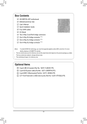
... GA-990FXA-UD7 motherboard Motherboard driver disk User's Manual Quick Installation Guide Four SATA cables I/O Shield Two 2-Way CrossFireX bridge connectors One 2-Way SLI bridge connector (Note) One 3-Way SLI bridge connector (Note) One 4-Way SLI bridge connector (Note) (Note ) To enable NVIDIA SLI technology, you obtain. The box contents are subject to GIGABYTE... notice. • The motherboard image is for reference only and the actual items shall depend on the product package you need SLI-supported graphics cards, BIOS, and driver.
... GA-990FXA-UD7 motherboard Motherboard driver disk User's Manual Quick Installation Guide Four SATA cables I/O Shield Two 2-Way CrossFireX bridge connectors One 2-Way SLI bridge connector (Note) One 3-Way SLI bridge connector (Note) One 4-Way SLI bridge connector (Note) (Note ) To enable NVIDIA SLI technology, you obtain. The box contents are subject to GIGABYTE... notice. • The motherboard image is for reference only and the actual items shall depend on the product package you need SLI-supported graphics cards, BIOS, and driver.

Manual
Page 8
GA-990FXA-UD7 Motherboard Block Diagram 4 PCI Express x8 2 PCI Express x16 CPU CLK+/- (200 MHz) 2 PCI Express x4 AM3+/AM3 CPU DDR3 2000(O.C.)/1866/1600/1333/1066 ... (100 MHz) x1 x1 x1 Etron Marvell Realtek EJ168 88SE9172 RTL8111E RJ45 2 USB 3.0/2.0 2 SATA 6Gb/s PCI Bus VIA VT6308 AMD SB950 CODEC 14 USB 2.0/1.1 Dual BIOS 6 SATA 6Gb/s LPC Bus iTE IT8720 2 IEEE 1394a PS/2 KB/Mouse Surround Speaker Out Center/Subwoofer Speaker Out Side Speaker Out MIC Line Out Line...
GA-990FXA-UD7 Motherboard Block Diagram 4 PCI Express x8 2 PCI Express x16 CPU CLK+/- (200 MHz) 2 PCI Express x4 AM3+/AM3 CPU DDR3 2000(O.C.)/1866/1600/1333/1066 ... (100 MHz) x1 x1 x1 Etron Marvell Realtek EJ168 88SE9172 RTL8111E RJ45 2 USB 3.0/2.0 2 SATA 6Gb/s PCI Bus VIA VT6308 AMD SB950 CODEC 14 USB 2.0/1.1 Dual BIOS 6 SATA 6Gb/s LPC Bus iTE IT8720 2 IEEE 1394a PS/2 KB/Mouse Surround Speaker Out Center/Subwoofer Speaker Out Side Speaker Out MIC Line Out Line...

Manual
Page 12
...product specifications and product-related information without prior notice. Unique Features ŠŠ Support for @BIOS ŠŠ Support for Q-Flash ŠŠ Support for Xpress BIOS Rescue ŠŠ Support for Download Center ŠŠ Support for Xpress Install ŠŠ...; Norton Internet Security (OEM version) Operating System ŠŠ Support for DualBIOS™ ŠŠ PnP 1.0a, DMI 2.0, SM BIOS 2.4, ACPI 1.0b Hardware ŠŠ System voltage detection Monitor ŠŠ CPU/System temperature detection ŠŠ CPU/System/Power fan...
...product specifications and product-related information without prior notice. Unique Features ŠŠ Support for @BIOS ŠŠ Support for Q-Flash ŠŠ Support for Xpress BIOS Rescue ŠŠ Support for Download Center ŠŠ Support for Xpress Install ŠŠ...; Norton Internet Security (OEM version) Operating System ŠŠ Support for DualBIOS™ ŠŠ PnP 1.0a, DMI 2.0, SM BIOS 2.4, ACPI 1.0b Hardware ŠŠ System voltage detection Monitor ŠŠ CPU/System temperature detection ŠŠ CPU/System/Power fan...

Manual
Page 16
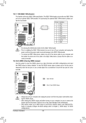
A memory module can be installed in only one DDR3 memory module is installed, the BIOS will double the original memory bandwidth. If you are divided into two channels and each channel has two memory sockets as following: Channel 0: DDR3_2, DDR3_4 ... guidelines before you begin to install the memory: • Make sure that memory of the same capacity, brand, speed, and chips be used . (Go to GIGABYTE's website for optimum performance. DS/SS DS/SS DDR3_1 DS/SS - Dual Channel mode cannot be used for the latest supported memory speeds and memory...
A memory module can be installed in only one DDR3 memory module is installed, the BIOS will double the original memory bandwidth. If you are divided into two channels and each channel has two memory sockets as following: Channel 0: DDR3_2, DDR3_4 ... guidelines before you begin to install the memory: • Make sure that memory of the same capacity, brand, speed, and chips be used . (Go to GIGABYTE's website for optimum performance. DS/SS DS/SS DDR3_1 DS/SS - Dual Channel mode cannot be used for the latest supported memory speeds and memory...

Manual
Page 18
.... 3. Make sure the card is securely seated in your card. Make sure the metal contacts on your expansion card(s). 7. If necessary, go to BIOS Setup to make any required BIOS changes for your computer. Example: Installing and Removing a PCI Express Graphics Card: • Installing a Graphics Card: Gently push down on the top...
.... 3. Make sure the card is securely seated in your card. Make sure the metal contacts on your expansion card(s). 7. If necessary, go to BIOS Setup to make any required BIOS changes for your computer. Example: Installing and Removing a PCI Express Graphics Card: • Installing a Graphics Card: Gently push down on the top...

Manual
Page 22
1-8 Onboard Buttons This motherboard has 3 quick buttons: power button, reset button and clearing CMOS button. date information and BIOS configurations) and reset the CMOS values to change hardware components or conduct hardware testing. The power button and reset button allow ...reset the computer in an open-case environment when they want to factory defaults when needed. Use the clearing CMOS button to Chapter 2, "BIOS Setup," for BIOS configurations). PW_SW: Power button RST_SW: Reset button CMOS_SW: Clearing CMOS button • Always turn on/off your computer and unplug the power...
1-8 Onboard Buttons This motherboard has 3 quick buttons: power button, reset button and clearing CMOS button. date information and BIOS configurations) and reset the CMOS values to change hardware components or conduct hardware testing. The power button and reset button allow ...reset the computer in an open-case environment when they want to factory defaults when needed. Use the clearing CMOS button to Chapter 2, "BIOS Setup," for BIOS configurations). PW_SW: Power button RST_SW: Reset button CMOS_SW: Clearing CMOS button • Always turn on/off your computer and unplug the power...

Manual
Page 25
... speed control design. Definition 1 GND 1 SYS_FAN1 2 +12V /Speed Control 3 Sense 4 Reserve SYS_FAN2/PWR_FAN: Pin No. F_PANEL(NH) 3) ATX4P (PCIe Power Connector) PWM Switch (X58A-OC) BIOS Switcher (X58A-OC) 1 The power connector provides auxiliary power to prevent your CPU and system from the power supply to connect it is the ground...
... speed control design. Definition 1 GND 1 SYS_FAN1 2 +12V /Speed Control 3 Sense 4 Reserve SYS_FAN2/PWR_FAN: Pin No. F_PANEL(NH) 3) ATX4P (PCIe Power Connector) PWM Switch (X58A-OC) BIOS Switcher (X58A-OC) 1 The power connector provides auxiliary power to prevent your CPU and system from the power supply to connect it is the ground...

Manual
Page 27
...correctly. - 27 - If a problem is in S1 sleep state. The LED keeps blinking when the sys- S1 Blinking tem is detected, the BIOS may issue beeps in S3/S4 sleep S3/S4/S5 Off state or powered off (S5). •• PW (Power Switch, Red): Connects to...;• CI (Chassis Intrusion Header, Gray): Connects to the pin assignments below. When connecting your system using the power switch (refer to Chapter 2, "BIOS Setup," "Power Management Setup," for information about beep codes. •• HD (Hard Drive Activity LED, Blue) Connects to this header according to ...
...correctly. - 27 - If a problem is in S1 sleep state. The LED keeps blinking when the sys- S1 Blinking tem is detected, the BIOS may issue beeps in S3/S4 sleep S3/S4/S5 Off state or powered off (S5). •• PW (Power Switch, Red): Connects to...;• CI (Chassis Intrusion Header, Gray): Connects to the pin assignments below. When connecting your system using the power switch (refer to Chapter 2, "BIOS Setup," "Power Management Setup," for information about beep codes. •• HD (Hard Drive Activity LED, Blue) Connects to this header according to ...

Manual
Page 28
... 2 GND (H61M-D2) 10 2 3 MIC2_R 3 MIC Power 4 -ACZ_DET 4 NC 5 LINE2_R 5 Line Out (R) 6 GND 6 NC 7 FAUDIO_JD 7 NC 8 No Pin 8 No Pin 9 LINE2_L 9 Line Out (L) DB_PORT 10 BIOS Switcher (X58A-OC) GND 10 NC DIP 1 23 1 • The front panel audio header su1pports HD audio by expansion cards) for digital audio output from...
... 2 GND (H61M-D2) 10 2 3 MIC2_R 3 MIC Power 4 -ACZ_DET 4 NC 5 LINE2_R 5 Line Out (R) 6 GND 6 NC 7 FAUDIO_JD 7 NC 8 No Pin 8 No Pin 9 LINE2_L 9 Line Out (L) DB_PORT 10 BIOS Switcher (X58A-OC) GND 10 NC DIP 1 23 1 • The front panel audio header su1pports HD audio by expansion cards) for digital audio output from...

Manual
Page 29
Hardware Installation Definition 1 VBUS 11 D2+ 2 SSRX1- 12 D2- 3 SSRX1+ 13 GND 4 GND 14 SSTX2+ 5 SSTX1- 15 SSTX2- 6 SSTX1+ 16 GND 7 GND 17 SSRX2+ DB_PORT BIOS 8 D1- 18 SSRX2- 9 D1+ 19 VBUS 10 NC 20 No Pin When the system is in S4/S5 mode, only the USB ports routed to ...
Hardware Installation Definition 1 VBUS 11 D2+ 2 SSRX1- 12 D2- 3 SSRX1+ 13 GND 4 GND 14 SSTX2+ 5 SSTX1- 15 SSTX2- 6 SSTX1+ 16 GND 7 GND 17 SSRX2+ DB_PORT BIOS 8 D1- 18 SSRX2- 9 D1+ 19 VBUS 10 NC 20 No Pin When the system is in S4/S5 mode, only the USB ports routed to ...
Manual
Page 30
...a few seconds. Failure to do so may cause damage to the motherboard. •• After system restart, go to BIOS Setup to load factory defaults (select Load Optimized Defaults) or manually configure the BIOS settings (refer to clear the CMOS values (e.g. Hardware Installation - 30 - Definition 1 TPA+ 2 TPA- 9 1 10...1394a header. • Prior to installing the IEEE 1394a bracket, be sure to touch the two pins for BIOS configurations). date information and BIOS configurations) and reset the CMOS values to the IEEE 1394a device. For purchasing the optional IEEE 1394a bracket, ...
...a few seconds. Failure to do so may cause damage to the motherboard. •• After system restart, go to BIOS Setup to load factory defaults (select Load Optimized Defaults) or manually configure the BIOS settings (refer to clear the CMOS values (e.g. Hardware Installation - 30 - Definition 1 TPA+ 2 TPA- 9 1 10...1394a header. • Prior to installing the IEEE 1394a bracket, be sure to touch the two pins for BIOS configurations). date information and BIOS configurations) and reset the CMOS values to the IEEE 1394a device. For purchasing the optional IEEE 1394a bracket, ...

Manual
Page 31
... 18 NC 19 NC 20 SUSCLK - 31 - Hardware Installation 16) BAT (Battery) The battery provides power to keep the values (such as BIOS configurations, date, and time information) in the CMOS when the computer is replaced with an incorrect model. • Contact the place of purchase ... your computer. • Always turn off your computer and unplug the power cord before replacing the battery. • Replace the battery with local environmental regulations. BIOS Switc 1 1 19 TPM w/housing 20 Pin No. 1 2 3 4 5 6 7 8 9 10 Definition LCLK GND LFRAME No Pin LRESET NC LAD3 LAD2 VCC3 LAD1 1 ...
... 18 NC 19 NC 20 SUSCLK - 31 - Hardware Installation 16) BAT (Battery) The battery provides power to keep the values (such as BIOS configurations, date, and time information) in the CMOS when the computer is replaced with an incorrect model. • Contact the place of purchase ... your computer. • Always turn off your computer and unplug the power cord before replacing the battery. • Replace the battery with local environmental regulations. BIOS Switc 1 1 19 TPM w/housing 20 Pin No. 1 2 3 4 5 6 7 8 9 10 Definition LCLK GND LFRAME No Pin LRESET NC LAD3 LAD2 VCC3 LAD1 1 ...

Manual
Page 33
...CMOS values.) - 33 - Refer to Chapter 5, "Troubleshooting," for how to boot. To see more advanced BIOS Setup menu options, you not flash the BIOS. To upgrade the BIOS, use either the GIGABYTE Q-Flash or @BIOS utility. • Q-Flash allows the user to quickly and easily upgrade or back up... BIOS without entering the operating system. • @BIOS is turned on the motherboard supplies the necessary ...
...CMOS values.) - 33 - Refer to Chapter 5, "Troubleshooting," for how to boot. To see more advanced BIOS Setup menu options, you not flash the BIOS. To upgrade the BIOS, use either the GIGABYTE Q-Flash or @BIOS utility. • Q-Flash allows the user to quickly and easily upgrade or back up... BIOS without entering the operating system. • @BIOS is turned on the motherboard supplies the necessary ...

Manual
Page 34
...GA-990FXA-UD7 F1a . . . . : BIOS Setup : XpressRecovery2 : Boot Menu : Qflash 04/22/2011-RD990-SB950-7A66FG01C-00 Function Keys Function Keys Function Keys: : POST SCREEN Press the key to Xpress Recovery2 during the POST. After system restart, the device boot order will directly boot from the device configured in Boot Menu. To show the BIOS...Press the key to access the Q-Flash utility directly without entering BIOS Setup. The LOGO Screen (Default) B. The POST Screen Motherboard Model BIOS Version Award Modular BIOS v6.00PG Copyright (C) 1984-2011, Award Software, Inc. A....
...GA-990FXA-UD7 F1a . . . . : BIOS Setup : XpressRecovery2 : Boot Menu : Qflash 04/22/2011-RD990-SB950-7A66FG01C-00 Function Keys Function Keys Function Keys: : POST SCREEN Press the key to Xpress Recovery2 during the POST. After system restart, the device boot order will directly boot from the device configured in Boot Menu. To show the BIOS...Press the key to access the Q-Flash utility directly without entering BIOS Setup. The LOGO Screen (Default) B. The POST Screen Motherboard Model BIOS Version Award Modular BIOS v6.00PG Copyright (C) 1984-2011, Award Software, Inc. A....

Manual
Page 35
... Without Saving ESC: Quit F8: Q-Flash Select Item F10: Save & Exit Setup Change CPU's Clock & Voltage F11: Save CMOS to BIOS F12: Load CMOS from BIOS BIOS Setup Program Function Keys Move the selection bar to select an item Execute command or enter the submenu Main Menu: Exit the...are for the current submenus Access the Q-Flash utility Display system information Save all the changes and exit the BIOS Setup program Save CMOS to BIOS Load CMOS from BIOS Main Menu Help The on-screen description of a highlighted setup option is not stable as shown below) appears...
... Without Saving ESC: Quit F8: Q-Flash Select Item F10: Save & Exit Setup Change CPU's Clock & Voltage F11: Save CMOS to BIOS F12: Load CMOS from BIOS BIOS Setup Program Function Keys Move the selection bar to select an item Execute command or enter the submenu Main Menu: Exit the...are for the current submenus Access the Q-Flash utility Display system information Save all the changes and exit the BIOS Setup program Save CMOS to BIOS Load CMOS from BIOS Main Menu Help The on-screen description of a highlighted setup option is not stable as shown below) appears...

Manual
Page 36
...to configure the system time and date, hard drive types, and the type of errors that stop the system boot, etc. Advanced BIOS Features Use this menu to configure the device boot order, advanced features available on the CPU, and the primary display adapter. Integrated ... disable password. A supervisor password allows you to a profile. It allows you to restrict access to the system and BIOS Setup. It allows you to restrict access to the system and BIOS Setup. First enter the profile name (to erase the default profile name, use this task.) Exit Without...
...to configure the system time and date, hard drive types, and the type of errors that stop the system boot, etc. Advanced BIOS Features Use this menu to configure the device boot order, advanced features available on the CPU, and the primary display adapter. Integrated ... disable password. A supervisor password allows you to a profile. It allows you to restrict access to the system and BIOS Setup. It allows you to restrict access to the system and BIOS Setup. First enter the profile name (to erase the default profile name, use this task.) Exit Without...

Manual
Page 37
BIOS Setup If this feature. - 37 - Core Performance Boost (Note) CPB Ratio (Note) Turbo CPB (Note) CPU Host Clock Control x CPU Frequency(MHz) PCIE Clock(MHz) ...
BIOS Setup If this feature. - 37 - Core Performance Boost (Note) CPB Ratio (Note) Turbo CPB (Note) CPU Host Clock Control x CPU Frequency(MHz) PCIE Clock(MHz) ...


