Manual
Page 2
Motherboard GA-970A-UD3 May 20, 2011 Motherboard GA-970A-UD3 May 20, 2011
Motherboard GA-970A-UD3 May 20, 2011 Motherboard GA-970A-UD3 May 20, 2011
Manual
Page 3
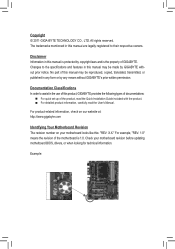
... documentations: For quick set-up of GIGABYTE. For product-related information, check on our website at: http://www.gigabyte.com Identifying Your Motherboard Revision The revision number on your motherboard revision before updating motherboard BIOS, drivers, or when looking for technical information... product information, carefully read the User's Manual. The trademarks mentioned in any form or by GIGABYTE without GIGABYTE's prior written permission. Example: Check your motherboard looks like this manual may be made by any means without prior notice. Changes to their ...
... documentations: For quick set-up of GIGABYTE. For product-related information, check on our website at: http://www.gigabyte.com Identifying Your Motherboard Revision The revision number on your motherboard revision before updating motherboard BIOS, drivers, or when looking for technical information... product information, carefully read the User's Manual. The trademarks mentioned in any form or by GIGABYTE without GIGABYTE's prior written permission. Example: Check your motherboard looks like this manual may be made by any means without prior notice. Changes to their ...
Manual
Page 4
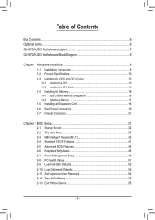
Table of Contents Box Contents...6 Optional Items...6 GA-970A-UD3 Motherboard Layout 7 GA-970A-UD3 Motherboard Block Diagram 8 Chapter 1 Hardware Installation 9 1-1 Installation Precautions 9 1-2 Product Specifications 10 1-3 Installing the CPU and CPU Cooler 13 1-3-1 Installing the CPU 13 1-3-2 Installing the CPU Cooler ...
Table of Contents Box Contents...6 Optional Items...6 GA-970A-UD3 Motherboard Layout 7 GA-970A-UD3 Motherboard Block Diagram 8 Chapter 1 Hardware Installation 9 1-1 Installation Precautions 9 1-2 Product Specifications 10 1-3 Installing the CPU and CPU Cooler 13 1-3-1 Installing the CPU 13 1-3-2 Installing the CPU Cooler ...
Manual
Page 6
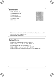
... port cable (Part No. 12CF1-1CM001-3*R) 2-port IEEE 1394a bracket (Part No. 12CF1-1IE008-0*R) 3.5" Front Panel with 2 USB 3.0/2.0 ports (Part No. 12CR1-FPX582-0*R) - 6 - Box Contents GA-970A-UD3 motherboard Motherboard driver disk User's Manual Quick Installation Guide Four SATA cables I/O Shield • The box contents above are subject to change without notice. • The...
... port cable (Part No. 12CF1-1CM001-3*R) 2-port IEEE 1394a bracket (Part No. 12CF1-1IE008-0*R) 3.5" Front Panel with 2 USB 3.0/2.0 ports (Part No. 12CR1-FPX582-0*R) - 6 - Box Contents GA-970A-UD3 motherboard Motherboard driver disk User's Manual Quick Installation Guide Four SATA cables I/O Shield • The box contents above are subject to change without notice. • The...
Manual
Page 7
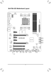
GA-970A-UD3 Motherboard Layout KB_MS_USB ATX_12V CPU_FAN OPTICALI USB_1394 R_USB R_USB30 Socket AM3+ PWR_FAN USB_LAN AUDIO Etron EJ168 PCIEX1_1 Realtek RTL8111E CODEC PCIEX16 PCIEX1_2 PCIEX1_3 VIA VT6308 iTE IT8720 PCIEX4 PCI1 PCI2 F_AUDIO AMD 970 GA-970A-UD3 DDR3_4 DDR3_2 DDR3_3 DDR3_1 ATX BAT AMD SB950 B_BIOS SATA3_4 SATA3_5 SATA3_2 SATA3_3 SATA3_0 SATA3_1 SYS_FAN1 F_USB1 Etron EJ168 M_BIOS CLR_CMOS F_USB30 SPDIF_O TPM F_1394 COMA F_USB3 F_USB2 SYS_FAN2 F_PANEL - 7 -
GA-970A-UD3 Motherboard Layout KB_MS_USB ATX_12V CPU_FAN OPTICALI USB_1394 R_USB R_USB30 Socket AM3+ PWR_FAN USB_LAN AUDIO Etron EJ168 PCIEX1_1 Realtek RTL8111E CODEC PCIEX16 PCIEX1_2 PCIEX1_3 VIA VT6308 iTE IT8720 PCIEX4 PCI1 PCI2 F_AUDIO AMD 970 GA-970A-UD3 DDR3_4 DDR3_2 DDR3_3 DDR3_1 ATX BAT AMD SB950 B_BIOS SATA3_4 SATA3_5 SATA3_2 SATA3_3 SATA3_0 SATA3_1 SYS_FAN1 F_USB1 Etron EJ168 M_BIOS CLR_CMOS F_USB30 SPDIF_O TPM F_1394 COMA F_USB3 F_USB2 SYS_FAN2 F_PANEL - 7 -
Manual
Page 8
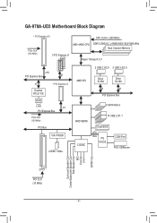
GA-970A-UD3 Motherboard Block Diagram 1 PCI Express x16 CPU CLK+/- (200 MHz) PCIe CLK (100 MHz) AM3+/AM3 CPU DDR3 2000(O.C.)/1866/1600/1333/1066 MHz Dual Channel ...
GA-970A-UD3 Motherboard Block Diagram 1 PCI Express x16 CPU CLK+/- (200 MHz) PCIe CLK (100 MHz) AM3+/AM3 CPU DDR3 2000(O.C.)/1866/1600/1333/1066 MHz Dual Channel ...
Manual
Page 9
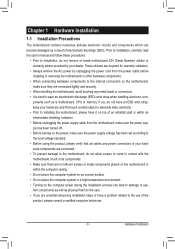
...the user's manual and follow these procedures: • Prior to installation, do not remove or break motherboard S/N (Serial Number) sticker or warranty sticker provided by unplugging the power cord from the motherboard, make sure the power supply has been turned off. • Before turning on the computer power...Always remove the AC power by your hands dry and first touch a metal object to eliminate static electricity. • Prior to installing the motherboard, please have it on top of an antistatic pad or within the computer casing. • Do not place the computer system on an uneven...
...the user's manual and follow these procedures: • Prior to installation, do not remove or break motherboard S/N (Serial Number) sticker or warranty sticker provided by unplugging the power cord from the motherboard, make sure the power supply has been turned off. • Before turning on the computer power...Always remove the AC power by your hands dry and first touch a metal object to eliminate static electricity. • Prior to installing the motherboard, please have it on top of an antistatic pad or within the computer casing. • Do not place the computer system on an uneven...

Manual
Page 12
... Center ŠŠ Support for Xpress Install ŠŠ Support for Xpress Recovery2 ŠŠ Support for EasyTune * Available functions in EasyTune may differ by motherboard model. ŠŠ Support for Easy Energy Saver ŠŠ Support for Smart Recovery ŠŠ Support for Auto Green ŠŠ Support for ON...
... Center ŠŠ Support for Xpress Install ŠŠ Support for Xpress Recovery2 ŠŠ Support for EasyTune * Available functions in EasyTune may differ by motherboard model. ŠŠ Support for Easy Energy Saver ŠŠ Support for Smart Recovery ŠŠ Support for Auto Green ŠŠ Support for ON...
Manual
Page 13
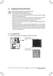
... socket.) • Apply an even and thin layer of thermal grease on the computer if the CPU cooler is not recommended that the motherboard supports the CPU. (Go to GIGABYTE's website for the peripherals. 1-3 Installing the CPU and CPU Cooler Read the following guidelines before installing the CPU to prevent hardware damage...
... socket.) • Apply an even and thin layer of thermal grease on the computer if the CPU cooler is not recommended that the motherboard supports the CPU. (Go to GIGABYTE's website for the peripherals. 1-3 Installing the CPU and CPU Cooler Read the following guidelines before installing the CPU to prevent hardware damage...

Manual
Page 14
... socket and gently insert the CPU into the fully locked position. Hardware Installation - 14 - Follow the steps below to correctly install the CPU into the motherboard CPU socket. • Before installing the CPU, make sure to turn off the computer and unplug the power cord from the power outlet to prevent...
... socket and gently insert the CPU into the fully locked position. Hardware Installation - 14 - Follow the steps below to correctly install the CPU into the motherboard CPU socket. • Before installing the CPU, make sure to turn off the computer and unplug the power cord from the power outlet to prevent...
Manual
Page 15
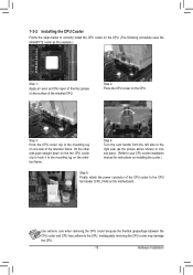
... CPU. Hardware Installation 1-3-2 Installing the CPU Cooler Follow the steps below to correctly install the CPU cooler on the CPU. (The following procedure uses the GIGABYTE cooler as the picture above shows) to lock into place. (Refer to your CPU cooler installation manual for instructions on installing the cooler.) Step 5: Finally... the CPU cooler and CPU may damage the CPU. - 15 - Step 4: Turn the cam handle from the left side to the mounting lug on the motherboard. Step 2: Place the CPU cooler on the CPU.
... CPU. Hardware Installation 1-3-2 Installing the CPU Cooler Follow the steps below to correctly install the CPU cooler on the CPU. (The following procedure uses the GIGABYTE cooler as the picture above shows) to lock into place. (Refer to your CPU cooler installation manual for instructions on installing the cooler.) Step 5: Finally... the CPU cooler and CPU may damage the CPU. - 15 - Step 4: Turn the cam handle from the left side to the mounting lug on the motherboard. Step 2: Place the CPU cooler on the CPU.
Manual
Page 16
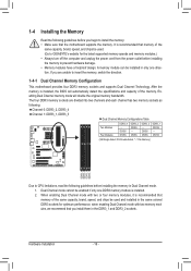
... and installed in the DDR3_1 and DDR3_2 sockets. Dual Channel mode cannot be installed in Dual Channel mode. 1. After the memory is recommended that the motherboard supports the memory. when enabling Dual Channel mode with two or four memory modules, it is installed. 2. 1-4 Installing the Memory Read the following guidelines ... module is recommended that you are divided into two channels and each channel has two memory sockets as following guidelines before you begin to GIGABYTE's website for optimum performance. A memory module can be enabled if only one direction.
... and installed in the DDR3_1 and DDR3_2 sockets. Dual Channel mode cannot be installed in Dual Channel mode. 1. After the memory is recommended that the motherboard supports the memory. when enabling Dual Channel mode with two or four memory modules, it is installed. 2. 1-4 Installing the Memory Read the following guidelines ... module is recommended that you are divided into two channels and each channel has two memory sockets as following guidelines before you begin to GIGABYTE's website for optimum performance. A memory module can be enabled if only one direction.

Manual
Page 17
..., make sure to turn off the computer and unplug the power cord from the power outlet to prevent damage to install DDR3 DIMMs on this motherboard. As indicated in the memory sockets. Notch DDR3 DIMM A DDR3 memory module has a notch, so it vertically into place when the memory module is securely...
..., make sure to turn off the computer and unplug the power cord from the power outlet to prevent damage to install DDR3 DIMMs on this motherboard. As indicated in the memory sockets. Notch DDR3 DIMM A DDR3 memory module has a notch, so it vertically into place when the memory module is securely...
Manual
Page 18
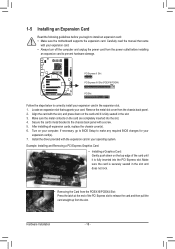
... on the card are completely inserted into the PCI Express slot. Secure the card's metal bracket to install an expansion card: • Make sure the motherboard supports the expansion card. 1-5 Installing an Expansion Card Read the following guidelines before installing an expansion card to release the card and then pull the...
... on the card are completely inserted into the PCI Express slot. Secure the card's metal bracket to install an expansion card: • Make sure the motherboard supports the expansion card. 1-5 Installing an Expansion Card Read the following guidelines before installing an expansion card to release the card and then pull the...

Manual
Page 20
... Audio." •• When removing the cable connected to a back panel connector, first remove the cable from your device and then remove it from the motherboard. •• When removing the cable, pull it side to side to prevent an electrical short inside the cable connector. Center/Subwoofer Speaker Out Jack...
... Audio." •• When removing the cable connected to a back panel connector, first remove the cable from your device and then remove it from the motherboard. •• When removing the cable, pull it side to side to prevent an electrical short inside the cable connector. Center/Subwoofer Speaker Out Jack...

Manual
Page 21
... 9) SPDIF_O 10) F_USB1/F_USB2/F_USB3 11) F_USB30 12) F_1394 13) COMA 14) TPM 15) BAT 16) CLR_CMOS Read the following guidelines before turning on the motherboard. - 21 - Hardware Installation
... 9) SPDIF_O 10) F_USB1/F_USB2/F_USB3 11) F_USB30 12) F_1394 13) COMA 14) TPM 15) BAT 16) CLR_CMOS Read the following guidelines before turning on the motherboard. - 21 - Hardware Installation

Manual
Page 22
... the power supply is not connected, the computer will not start. If the 12V power connector is turned off and all the components on the motherboard. To meet expansion requirements, it is used (500W or greater). If a power supply is recommended that a power supply that can withstand high power consumption be...
... the power supply is not connected, the computer will not start. If the 12V power connector is turned off and all the components on the motherboard. To meet expansion requirements, it is used (500W or greater). If a power supply is recommended that a power supply that can withstand high power consumption be...

Manual
Page 23
When connecting a fan cable, be sure to connect it is the ground wire). The motherboard supports CPU fan speed control, which requires the use of even number.) the SATA cable to prevent your SATA hard • A RAID 10 configuration requires ... design. The AMD SB950 South Bridge supports RAID 0, RAID 1, RAID 5, RAID 10, and JBOD. drive. - 23 - Hardware Installation 3/4/5) CPU_FAN/SYS_FAN1/SYS_FAN2/PWR_FAN (Fan Headers) The motherboard has a 4-pin CPU fan header (CPU_FAN), a 4-pin (SYS_FAN1) and a 3-pin (SYS_FAN2) system fan headers, and a 3-pin power fan header (PWR_FAN).
When connecting a fan cable, be sure to connect it is the ground wire). The motherboard supports CPU fan speed control, which requires the use of even number.) the SATA cable to prevent your SATA hard • A RAID 10 configuration requires ... design. The AMD SB950 South Bridge supports RAID 0, RAID 1, RAID 5, RAID 10, and JBOD. drive. - 23 - Hardware Installation 3/4/5) CPU_FAN/SYS_FAN1/SYS_FAN2/PWR_FAN (Fan Headers) The motherboard has a 4-pin CPU fan header (CPU_FAN), a 4-pin (SYS_FAN1) and a 3-pin (SYS_FAN2) system fan headers, and a 3-pin power fan header (PWR_FAN).
Manual
Page 25
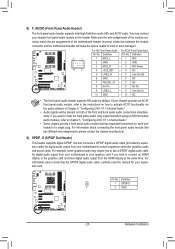
... read the manual for digital audio output from your chassis front panel audio module to the instructions on each wire instead of the motherboard header. Hardware Installation For HD Front Panel Audio: For AC'97 Front Panel Audio: Pin No. Definition 1 SPDIFO 1 2 ...GND - 25 - Incorrect connection between the module connector and the motherboard header will be present on both of the front and back panel audio connections simultaneously. Definition Pin No. Definition F_AUDIO(H) 9 1 10 2 1 MIC2_L...
... read the manual for digital audio output from your chassis front panel audio module to the instructions on each wire instead of the motherboard header. Hardware Installation For HD Front Panel Audio: For AC'97 Front Panel Audio: Pin No. Definition 1 SPDIFO 1 2 ...GND - 25 - Incorrect connection between the module connector and the motherboard header will be present on both of the front and back panel audio connections simultaneously. Definition Pin No. Definition F_AUDIO(H) 9 1 10 2 1 MIC2_L...
Manual
Page 29
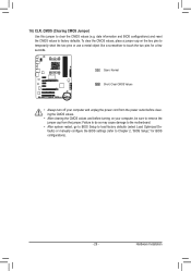
Failure to do so may cause damage to the motherboard. •• After system restart, go to BIOS Setup to load factory defaults (select Load Optimized Defaults) or manually configure the BIOS settings (refer to ...
Failure to do so may cause damage to the motherboard. •• After system restart, go to BIOS Setup to load factory defaults (select Load Optimized Defaults) or manually configure the BIOS settings (refer to ...


