Manual
Page 2
Motherboard GA-970A-D3 May 20, 2011 Motherboard GA-970A-D3 May 20, 2011
Motherboard GA-970A-D3 May 20, 2011 Motherboard GA-970A-D3 May 20, 2011
Manual
Page 3
... rights reserved. For product-related information, check on our website at: http://www.gigabyte.com Identifying Your Motherboard Revision The revision number on your motherboard revision before updating motherboard BIOS, drivers, or when looking for technical information. Documentation Classifications In order to assist... of documentations: For quick set-up of GIGABYTE. Copyright © 2011 GIGA-BYTE TECHNOLOGY CO., LTD. Changes to their respective owners. For example, "REV: 1.0" means the revision of the motherboard is the property of the product, read the Quick ...
... rights reserved. For product-related information, check on our website at: http://www.gigabyte.com Identifying Your Motherboard Revision The revision number on your motherboard revision before updating motherboard BIOS, drivers, or when looking for technical information. Documentation Classifications In order to assist... of documentations: For quick set-up of GIGABYTE. Copyright © 2011 GIGA-BYTE TECHNOLOGY CO., LTD. Changes to their respective owners. For example, "REV: 1.0" means the revision of the motherboard is the property of the product, read the Quick ...
Manual
Page 4
Table of Contents Box Contents...6 Optional Items...6 GA-970A-D3 Motherboard Layout 7 GA-970A-D3 Motherboard Block Diagram 8 Chapter 1 Hardware Installation 9 1-1 Installation Precautions 9 1-2 Product Specifications 10 1-3 Installing the CPU and CPU Cooler 13 1-3-1 Installing the CPU 13 1-3-2 Installing the CPU Cooler ...
Table of Contents Box Contents...6 Optional Items...6 GA-970A-D3 Motherboard Layout 7 GA-970A-D3 Motherboard Block Diagram 8 Chapter 1 Hardware Installation 9 1-1 Installation Precautions 9 1-2 Product Specifications 10 1-3 Installing the CPU and CPU Cooler 13 1-3-1 Installing the CPU 13 1-3-2 Installing the CPU Cooler ...
Manual
Page 6
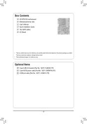
The box contents are for reference only. Box Contents GA-970A-D3 motherboard Motherboard driver disk User's Manual Quick Installation Guide Two SATA cables I/O Shield • The box contents above are subject to change without notice. • The motherboard image is for reference only and the actual items shall depend on the product package you obtain. Optional Items 2-port USB 2.0 bracket (Part No. 12CR1-1UB030-5*R) 2-port SATA power cable (Part No. 12CF1-2SERPW-0*R) COM port cable (Part No. 12CF1-1CM001-3*R) - 6 -
The box contents are for reference only. Box Contents GA-970A-D3 motherboard Motherboard driver disk User's Manual Quick Installation Guide Two SATA cables I/O Shield • The box contents above are subject to change without notice. • The motherboard image is for reference only and the actual items shall depend on the product package you obtain. Optional Items 2-port USB 2.0 bracket (Part No. 12CR1-1UB030-5*R) 2-port SATA power cable (Part No. 12CF1-2SERPW-0*R) COM port cable (Part No. 12CF1-1CM001-3*R) - 6 -
Manual
Page 7
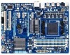
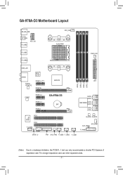
For a longer expansion card, use other expansion slots. - 7 - GA-970A-D3 Motherboard Layout KB_MS_USB OPTICAL R_USB2 ATX_12V CPU_FAN Socket AM3+ R_USB1 R_USB30 PWR_FAN USB_LAN AUDIO Etron EJ168 PCIEX1_1 (Note) AMD 970 ATX Realtek RTL8111E PCIEX16 iTE IT8720 DDR3_4 DDR3_2 DDR3_3 DDR3_1 CODEC PCIEX1_2 PCIEX1_3 PCIEX4 GA-970A-D3 BAT SATA3_5 SATA3_4 AMD SB950 SATA3_3 SATA3_2 SATA3_1 SATA3_0 PCI1...
For a longer expansion card, use other expansion slots. - 7 - GA-970A-D3 Motherboard Layout KB_MS_USB OPTICAL R_USB2 ATX_12V CPU_FAN Socket AM3+ R_USB1 R_USB30 PWR_FAN USB_LAN AUDIO Etron EJ168 PCIEX1_1 (Note) AMD 970 ATX Realtek RTL8111E PCIEX16 iTE IT8720 DDR3_4 DDR3_2 DDR3_3 DDR3_1 CODEC PCIEX1_2 PCIEX1_3 PCIEX4 GA-970A-D3 BAT SATA3_5 SATA3_4 AMD SB950 SATA3_3 SATA3_2 SATA3_1 SATA3_0 PCI1...
Manual
Page 8
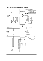
GA-970A-D3 Motherboard Block Diagram 1 PCI Express x16 AM3+/AM3 CPU CPU CLK+/- (200 MHz) DDR3 2000 (O.C.)/1866/1600/ 1333/1066 MHz Dual Channel Memory PCIe CLK (100 ...
GA-970A-D3 Motherboard Block Diagram 1 PCI Express x16 AM3+/AM3 CPU CPU CLK+/- (200 MHz) DDR3 2000 (O.C.)/1866/1600/ 1333/1066 MHz Dual Channel Memory PCIe CLK (100 ...
Manual
Page 9
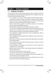
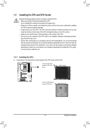
...to wear an electrostatic discharge (ESD) wrist strap when handling electronic com- Chapter 1 Hardware Installation 1-1 Installation Precautions The motherboard contains numerous delicate electronic circuits and components which can lead to damage to system components as well as physical harm to the...8226; When connecting hardware components to the internal connectors on the computer power during the installation process can become damaged as a motherboard, CPU or memory. Hardware Installation Prior to installation, carefully read the user's manual and follow these procedures: ••...
...to wear an electrostatic discharge (ESD) wrist strap when handling electronic com- Chapter 1 Hardware Installation 1-1 Installation Precautions The motherboard contains numerous delicate electronic circuits and components which can lead to damage to system components as well as physical harm to the...8226; When connecting hardware components to the internal connectors on the computer power during the installation process can become damaged as a motherboard, CPU or memory. Hardware Installation Prior to installation, carefully read the user's manual and follow these procedures: ••...
Manual
Page 12
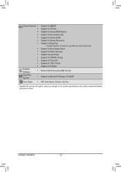
... Center ŠŠ Support for Xpress Install ŠŠ Support for Xpress Recovery2 ŠŠ Support for EasyTune * Available functions in EasyTune may differ by motherboard model. ŠŠ Support for Easy Energy Saver ŠŠ Support for Smart Recovery ŠŠ Support for Auto Green ŠŠ Support for ON...
... Center ŠŠ Support for Xpress Install ŠŠ Support for Xpress Recovery2 ŠŠ Support for EasyTune * Available functions in EasyTune may differ by motherboard model. ŠŠ Support for Easy Energy Saver ŠŠ Support for Smart Recovery ŠŠ Support for Auto Green ŠŠ Support for ON...
Manual
Page 13
...8226; Locate the pin one (denoted by a small triangle) of thermal grease on the computer if the CPU cooler is not recommended that the motherboard supports the CPU. (Go to your hardware specifications including the CPU, graphics card, memory, hard drive, etc. 1-3-1 Installing the CPU A. ...that the system bus frequency be inserted if oriented incorrectly. (Or you wish to set beyond the standard specifications, please do so according to GIGABYTE's website for the peripherals. Locate the pin one of the Socket AM3+ Socket A Small Triangle Marking Denotes CPU Pin One AM3+/AM3 ...
...8226; Locate the pin one (denoted by a small triangle) of thermal grease on the computer if the CPU cooler is not recommended that the motherboard supports the CPU. (Go to your hardware specifications including the CPU, graphics card, memory, hard drive, etc. 1-3-1 Installing the CPU A. ...that the system bus frequency be inserted if oriented incorrectly. (Or you wish to set beyond the standard specifications, please do so according to GIGABYTE's website for the peripherals. Locate the pin one of the Socket AM3+ Socket A Small Triangle Marking Denotes CPU Pin One AM3+/AM3 ...
Manual
Page 14
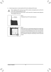
... fully locked position. Hardware Installation - 14 - B. The CPU cannot fit in if oriented incorrectly. Follow the steps below to correctly install the CPU into the motherboard CPU socket. •• Before installing the CPU, make sure to turn off the computer and unplug the power cord from the power outlet to...
... fully locked position. Hardware Installation - 14 - B. The CPU cannot fit in if oriented incorrectly. Follow the steps below to correctly install the CPU into the motherboard CPU socket. •• Before installing the CPU, make sure to turn off the computer and unplug the power cord from the power outlet to...
Manual
Page 15
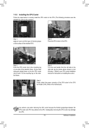
Step 3: Hook the CPU cooler clip to the mounting lug on the motherboard. Inadequately removing the CPU cooler may adhere to the CPU. Step 4: Turn the cam handle from the left side to the right side (as the ... the CPU. - 15 - 1-3-2 Installing the CPU Cooler Follow the steps below to correctly install the CPU cooler on the CPU. (The following procedure uses the GIGABYTE cooler as the picture above shows) to lock into place. (Refer to your CPU cooler installation manual for instructions on installing the cooler.) Step 5: Finally...
Step 3: Hook the CPU cooler clip to the mounting lug on the motherboard. Inadequately removing the CPU cooler may adhere to the CPU. Step 4: Turn the cam handle from the left side to the right side (as the ... the CPU. - 15 - 1-3-2 Installing the CPU Cooler Follow the steps below to correctly install the CPU cooler on the CPU. (The following procedure uses the GIGABYTE cooler as the picture above shows) to lock into place. (Refer to your CPU cooler installation manual for instructions on installing the cooler.) Step 5: Finally...
Manual
Page 16
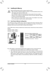
... DDR3 memory sockets are unable to insert the memory, switch the direction. 1-4-1 Dual Channel Memory Configuration This motherboard provides four DDR3 memory sockets and supports Dual Channel Technology. Dual Channel mode cannot be installed in only one... DDR3_3 Two Modules - - When enabling Dual Channel mode with two memory modules, we recommend that the motherboard supports the memory. It is recommended that memory of the same capacity, brand, speed, and chips be... DS=Double-Sided, "- -"=No Memory) DDR3_4 DDR3_2 DDR3_3 DDR3_1 Due to GIGABYTE's website for optimum performance.
... DDR3 memory sockets are unable to insert the memory, switch the direction. 1-4-1 Dual Channel Memory Configuration This motherboard provides four DDR3 memory sockets and supports Dual Channel Technology. Dual Channel mode cannot be installed in only one... DDR3_3 Two Modules - - When enabling Dual Channel mode with two memory modules, we recommend that the motherboard supports the memory. It is recommended that memory of the same capacity, brand, speed, and chips be... DS=Double-Sided, "- -"=No Memory) DDR3_4 DDR3_2 DDR3_3 DDR3_1 Due to GIGABYTE's website for optimum performance.
Manual
Page 17
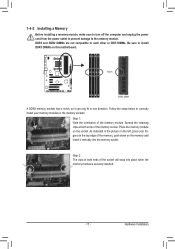
..., make sure to turn off the computer and unplug the power cord from the power outlet to prevent damage to install DDR3 DIMMs on this motherboard. Step 1: Note the orientation of the memory socket. As indicated in the picture on the left, place your memory modules in one direction. Place the...
..., make sure to turn off the computer and unplug the power cord from the power outlet to prevent damage to install DDR3 DIMMs on this motherboard. Step 1: Note the orientation of the memory socket. As indicated in the picture on the left, place your memory modules in one direction. Place the...
Manual
Page 18
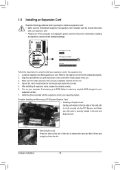
... off the computer and unplug the power cord from the power outlet before you begin to install an expansion card: •• Make sure the motherboard supports the expansion card. Make sure the card is securely seated in your expansion card in the slot. 3. 1-5 Installing an Expansion Card Read the following...
... off the computer and unplug the power cord from the power outlet before you begin to install an expansion card: •• Make sure the motherboard supports the expansion card. Make sure the card is securely seated in your expansion card in the slot. 3. 1-5 Installing an Expansion Card Read the following...
Manual
Page 19
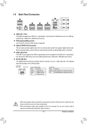
... connected to the USB 2.0/1.1 specification. Hardware Installation Before using this port to an external audio system that your device and then remove it from the motherboard. •• When removing the cable, pull it side to side to 1 Gbps data rate. PS/2 Keyboard/Mouse Port Use this feature, ensure that supports...
... connected to the USB 2.0/1.1 specification. Hardware Installation Before using this port to an external audio system that your device and then remove it from the motherboard. •• When removing the cable, pull it side to side to 1 Gbps data rate. PS/2 Keyboard/Mouse Port Use this feature, ensure that supports...
Manual
Page 21
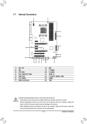
... wish to connect. •• Before installing the devices, be sure to the devices. •• After installing the device and before turning on the motherboard. - 21 - Unplug the power cord from the power outlet to prevent damage to turn off the devices and your computer. Hardware Installation
... wish to connect. •• Before installing the devices, be sure to the devices. •• After installing the device and before turning on the motherboard. - 21 - Unplug the power cord from the power outlet to prevent damage to turn off the devices and your computer. Hardware Installation
Manual
Page 22
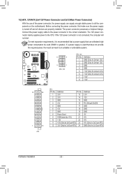
... mainly supplies power to the power connector in the correct orientation. To meet expansion requirements, it is turned off and all the components on the motherboard. If a power supply is not connected, the computer will not start. Connect the power supply cable to the CPU. 1/2) ATX_12V/ATX (2x4 12V Power Connector...
... mainly supplies power to the power connector in the correct orientation. To meet expansion requirements, it is turned off and all the components on the motherboard. If a power supply is not connected, the computer will not start. Connect the power supply cable to the CPU. 1/2) ATX_12V/ATX (2x4 12V Power Connector...
Manual
Page 23
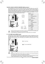
...clear the CMOS values, place a jumper cap on the headers. 6) CLR_CMOS (Clearing CMOS Jumper) Use this jumper to factory defaults. The motherboard supports CPU fan speed control, which requires the use a metal object like a screwdriver to prevent your computer, be sure to the CPU ...the CMOS values to clear the CMOS values (e.g. When connecting a fan cable, be installed inside the chassis. 3/4/5) CPU_FAN/SYS_FAN1/SYS_FAN2/PWR_FAN (Fan Headers) The motherboard has a 4-pin CPU fan header (CPU_FAN), a 3-pin (SYS_FAN2) and a 4-pin (SYS_ FAN1) system fan headers, and a 3-pin power fan ...
...clear the CMOS values, place a jumper cap on the headers. 6) CLR_CMOS (Clearing CMOS Jumper) Use this jumper to factory defaults. The motherboard supports CPU fan speed control, which requires the use a metal object like a screwdriver to prevent your computer, be sure to the CPU ...the CMOS values to clear the CMOS values (e.g. When connecting a fan cable, be installed inside the chassis. 3/4/5) CPU_FAN/SYS_FAN1/SYS_FAN2/PWR_FAN (Fan Headers) The motherboard has a 4-pin CPU fan header (CPU_FAN), a 3-pin (SYS_FAN2) and a 4-pin (SYS_ FAN1) system fan headers, and a 3-pin power fan ...
Manual
Page 26
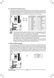
...connecting the S/PDIF digital audio cable, carefully read the manual for your expansion card. For example, some graphics cards may connect your motherboard to Chapter 5, "Configuring 2/4/5.1/7.1-Channel Audio." • Some chassis provide a fronPtWpManSewlitachu(dXi5o8Am-OoCd)ule that has different wire assignments, please...panel audio header supports Intel High Definition audio (HD) and AC'97 audio. Incorrect connection between the module connector and the motherboard header will be present on how to the graphics card and have digital audio output from the HDMI display at the same...
...connecting the S/PDIF digital audio cable, carefully read the manual for your expansion card. For example, some graphics cards may connect your motherboard to Chapter 5, "Configuring 2/4/5.1/7.1-Channel Audio." • Some chassis provide a fronPtWpManSewlitachu(dXi5o8Am-OoCd)ule that has different wire assignments, please...panel audio header supports Intel High Definition audio (HD) and AC'97 audio. Incorrect connection between the module connector and the motherboard header will be present on how to the graphics card and have digital audio output from the HDMI display at the same...
Manual
Page 29
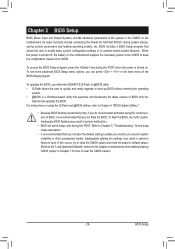
... of BIOS, it with caution. To access the BIOS Setup program, press the key during the POST when the power is turned on the motherboard. Its major functions include conducting the Power-On Self-Test (POST) during the POST. BIOS Setup BIOS includes a BIOS Setup program that searches... and downloads the latest version of the BIOS Setup program. To upgrade the BIOS, use either the GIGABYTE Q-Flash or @BIOS utility. •• Q-Flash allows the user to the "Load Optimized Defaults" section in this chapter or introductions of ...
... of BIOS, it with caution. To access the BIOS Setup program, press the key during the POST when the power is turned on the motherboard. Its major functions include conducting the Power-On Self-Test (POST) during the POST. BIOS Setup BIOS includes a BIOS Setup program that searches... and downloads the latest version of the BIOS Setup program. To upgrade the BIOS, use either the GIGABYTE Q-Flash or @BIOS utility. •• Q-Flash allows the user to the "Load Optimized Defaults" section in this chapter or introductions of ...


