
Manual
Page 1
GA-965QM-DS2 (rev. 2.0) Intel® CoreTM 2 Extreme quad-core / CoreTM 2 Quad / Intel® CoreTM 2 Extreme dual-core / CoreTM 2 Duo / Intel® Pentium® Processor Extreme Edition / Intel® Pentium® D / Pentium® 4 LGA775 Processor Motherboard User's Manual Rev. 2002 12ME-965QMDS2-2002R * The WEEE marking on the product indicates this product must not be...
GA-965QM-DS2 (rev. 2.0) Intel® CoreTM 2 Extreme quad-core / CoreTM 2 Quad / Intel® CoreTM 2 Extreme dual-core / CoreTM 2 Duo / Intel® Pentium® Processor Extreme Edition / Intel® Pentium® D / Pentium® 4 LGA775 Processor Motherboard User's Manual Rev. 2002 12ME-965QMDS2-2002R * The WEEE marking on the product indicates this product must not be...

Manual
Page 2
Motherboard GA-965QM-DS2 Jan. 9, 2007 Motherboard GA-965QM-DS2 Jan. 9, 2007
Motherboard GA-965QM-DS2 Jan. 9, 2007 Motherboard GA-965QM-DS2 Jan. 9, 2007
Manual
Page 4
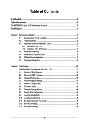
Table of Contents ItemChecklist ...6 OptionalAccessories ...6 GA-965QM-DS2 (rev. 2.0) Motherboard Layout 7 Block Diagram ...8 Chapter 1 Hardware Installation 9 1-1 Considerations Prior to Installation 9 1-2 Feature Summary 10 1-3 Installation of the CPU and CPU Cooler 12 1-3-1 Installation of the CPU ...
Table of Contents ItemChecklist ...6 OptionalAccessories ...6 GA-965QM-DS2 (rev. 2.0) Motherboard Layout 7 Block Diagram ...8 Chapter 1 Hardware Installation 9 1-1 Considerations Prior to Installation 9 1-2 Feature Summary 10 1-3 Installation of the CPU and CPU Cooler 12 1-3-1 Installation of the CPU ...

Manual
Page 7
GA-965QM-DS2 DDRII1 DDRII2 DDRII3 DDRII4 IT8718 GA-965QM-DS2 (rev. 2.0) Motherboard Layout KB_MS LGA775 CPU_FAN ATX VGA COM LPT USB LAN1 F_AUDIO R_USB FDD ATX_12V AUDIO Intel® Q965 Nineveh 82566DM PCIE_16 PCI1 PCI2 CD_IN PCIE_1 CODEC SPDIF_IO COMB TPM_CLR Intel® ICH8DO IDE GIGABYTE SATA2 BATTERY F_PANEL 2_BIOS 1_BIOS TPM Controller CI F_USB1 F_USB2 F_USB3 CLR_CMOS SATAII2 SATAII4 SATAII0 PWR_LED SYS_FAN SATAII5 SATAII3 SATAII1 - 7 -
GA-965QM-DS2 DDRII1 DDRII2 DDRII3 DDRII4 IT8718 GA-965QM-DS2 (rev. 2.0) Motherboard Layout KB_MS LGA775 CPU_FAN ATX VGA COM LPT USB LAN1 F_AUDIO R_USB FDD ATX_12V AUDIO Intel® Q965 Nineveh 82566DM PCIE_16 PCI1 PCI2 CD_IN PCIE_1 CODEC SPDIF_IO COMB TPM_CLR Intel® ICH8DO IDE GIGABYTE SATA2 BATTERY F_PANEL 2_BIOS 1_BIOS TPM Controller CI F_USB1 F_USB2 F_USB3 CLR_CMOS SATAII2 SATAII4 SATAII0 PWR_LED SYS_FAN SATAII5 SATAII3 SATAII1 - 7 -

Manual
Page 8
... x16 LAN PCI Express x1 RJ45 PCIe CLK (100 MHz) x1 Nineveh 82566DM GLCI x1 PCI Express Bus ATA-33/66/100/ 133 IDE Channel GIGABYTE SATA2 Intel® Q965 Intel® ICH8DO Dual Channel Memory GMCH CLK (266/200/133 MHz) BIOS 6 SATA 3Gb/s 10 USB Ports PCI Bus CODEC.../Subwoofer Speaker Out Side Speaker Out MIC Line-Out Line-In SPDIF In SPDIF Out (Note) To use a DDRII 800/667 memory module on the motherboard, you must install a 1066/800 MHz FSB processor. - 8 -
... x16 LAN PCI Express x1 RJ45 PCIe CLK (100 MHz) x1 Nineveh 82566DM GLCI x1 PCI Express Bus ATA-33/66/100/ 133 IDE Channel GIGABYTE SATA2 Intel® Q965 Intel® ICH8DO Dual Channel Memory GMCH CLK (266/200/133 MHz) BIOS 6 SATA 3Gb/s 10 USB Ports PCI Bus CODEC.../Subwoofer Speaker Out Side Speaker Out MIC Line-Out Line-In SPDIF In SPDIF Out (Note) To use a DDRII 800/667 memory module on the motherboard, you must install a 1066/800 MHz FSB processor. - 8 -

Manual
Page 9
...Installation 1-1 Considerations Prior to Installation Preparing Your Computer The motherboard contains numerous delicate electronic circuits and components which can lead to damage to system components as well as physical harm to be an unofficial Gigabyte product. - 9 - Damage due to wear an ...electrostatic discharge (ESD) cuff when handling electronic components (CPU, RAM). 4. When handling the motherboard, avoid touching any hardware, please first carefully read the...
...Installation 1-1 Considerations Prior to Installation Preparing Your Computer The motherboard contains numerous delicate electronic circuits and components which can lead to damage to system components as well as physical harm to be an unofficial Gigabyte product. - 9 - Damage due to wear an ...electrostatic discharge (ESD) cuff when handling electronic components (CPU, RAM). 4. When handling the motherboard, avoid touching any hardware, please first carefully read the...

Manual
Page 10
... additional 6 ports by cables Š 1 COMB connector Š 1 TPM_CLR connector Š 1 Chassis Intrusion connector Š 1 power LED connector GA-965QM-DS2 (rev. 2.0) Motherboard - 10 - Supports RAID 0, RAID 1, RAID 5, and RAID 10 for Serial ATA Š GIGABYTE SATA2 Controller - 1 IDE connector with CPU Front Side Bus Š Supports 1066/800/533 MHz FSB Chipset Š Northbridge...
... additional 6 ports by cables Š 1 COMB connector Š 1 TPM_CLR connector Š 1 Chassis Intrusion connector Š 1 power LED connector GA-965QM-DS2 (rev. 2.0) Motherboard - 10 - Supports RAID 0, RAID 1, RAID 5, and RAID 10 for Serial ATA Š GIGABYTE SATA2 Controller - 1 IDE connector with CPU Front Side Bus Š Supports 1066/800/533 MHz FSB Chipset Š Northbridge...
Manual
Page 11
... Internet Security (OEM revision) Form Factor Š Micro ATX form factor; 24.4cm x 24.4cm (Note 1) To use a DDRII 800/667 memory module on the motherboard, you must install a 1066/800 MHz FSB processor. (Note 2) EasyTune functions may vary depending on different...
... Internet Security (OEM revision) Form Factor Š Micro ATX form factor; 24.4cm x 24.4cm (Note 1) To use a DDRII 800/667 memory module on the motherboard, you must install a 1066/800 MHz FSB processor. (Note 2) EasyTune functions may vary depending on different...
Manual
Page 12
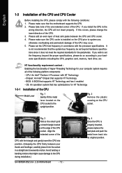
... the functionality of Hyper-Threading Technology for your thumb and forefinger, carefully place it into its original position. BIOS: A BIOS that the motherboard supports the CPU. 2. Fig. 2 Remove the plastic covering on the edge of the CPU socket. Avoid twisting or bending motions that ... Installation of the CPU Metal Lever Fig. 1 Gently lift the metal lever located on the CPU prior to the CPU during installation.) GA-965QM-DS2 (rev. 2.0) Motherboard - 12 - If this occurs, please change the insert direction of the CPU. Chipset: An Intel® Chipset that might cause...
... the functionality of Hyper-Threading Technology for your thumb and forefinger, carefully place it into its original position. BIOS: A BIOS that the motherboard supports the CPU. 2. Fig. 2 Remove the plastic covering on the edge of the CPU socket. Avoid twisting or bending motions that ... Installation of the CPU Metal Lever Fig. 1 Gently lift the metal lever located on the CPU prior to the CPU during installation.) GA-965QM-DS2 (rev. 2.0) Motherboard - 12 - If this occurs, please change the insert direction of the CPU. Chipset: An Intel® Chipset that might cause...

Manual
Page 13
... suggested that either thermal tape rather than heat paste be used for detailed installation instructions, please refer to the CPU fan header located on the motherboard. Fig. 2 (Turning the push pin along the direction of arrow is to remove the CPU cooler, on the contrary, is to install.) Please note the... direction of the heat paste. The CPU cooler may adhere to the pin hole on the motherboard.Pressing down the push pins diagonally. If the push pin is inserted as the picture, the installation is only for Intel boxed fan) Fig. 3 Place...
... suggested that either thermal tape rather than heat paste be used for detailed installation instructions, please refer to the CPU fan header located on the motherboard. Fig. 2 (Turning the push pin along the direction of arrow is to remove the CPU cooler, on the contrary, is to install.) Please note the... direction of the heat paste. The CPU cooler may adhere to the pin hole on the motherboard.Pressing down the push pins diagonally. If the push pin is inserted as the picture, the installation is only for Intel boxed fan) Fig. 3 Place...
Manual
Page 14
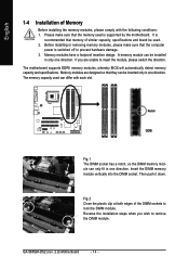
...DIMM memory module vertically into the DIMM socket. A memory module can be inserted only in one direction. The motherboard supports DDRII memory modules, whereby BIOS will automatically detect memory capacity and specifications. Memory modules are unable to ... installing the memory modules, please comply with each slot. The memory capacity used is supported by the motherboard. English 1-4 Installation of the DIMM sockets to lock the DIMM module. Please make sure that the ...so that the memory used can only fit in one direction. GA-965QM-DS2 (rev. 2.0) Motherboard - 14 -
...DIMM memory module vertically into the DIMM socket. A memory module can be inserted only in one direction. The motherboard supports DDRII memory modules, whereby BIOS will automatically detect memory capacity and specifications. Memory modules are unable to ... installing the memory modules, please comply with each slot. The memory capacity used is supported by the motherboard. English 1-4 Installation of the DIMM sockets to lock the DIMM module. Please make sure that the ...so that the memory used can only fit in one direction. GA-965QM-DS2 (rev. 2.0) Motherboard - 14 -
Manual
Page 16
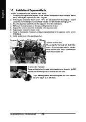
... VGA card: Please align the VGA card with the PCI Express x16 slot and press down on the card are fully seated in the slot. 5. GA-965QM-DS2 (rev. 2.0) Motherboard - 16 - Press the expansion card firmly into the expansion slot in the operating system. Ground yourself to prevent damage to secure the slot bracket...
... VGA card: Please align the VGA card with the PCI Express x16 slot and press down on the card are fully seated in the slot. 5. GA-965QM-DS2 (rev. 2.0) Motherboard - 16 - Press the expansion card firmly into the expansion slot in the operating system. Ground yourself to prevent damage to secure the slot bracket...

Manual
Page 18
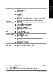
... 5) FDD 6) IDE 7) SATAII0 / 1 / 2 / 3 / 4 / 5 8) PWR_LED 9) BATTERY 10) F_PANEL 11) F_AUDIO 12) CD_IN 13) SPDIF_IO 14) F_USB1 / F_USB2 / F_USB3 15) COMB 16) CLR_CMOS 17) CI 18) TPM_CLR GA-965QM-DS2 (rev. 2.0) Motherboard - 18 - Only microphones still MUST be connected to the default Mic In jack ( ).
... 5) FDD 6) IDE 7) SATAII0 / 1 / 2 / 3 / 4 / 5 8) PWR_LED 9) BATTERY 10) F_PANEL 11) F_AUDIO 12) CD_IN 13) SPDIF_IO 14) F_USB1 / F_USB2 / F_USB3 15) COMB 16) CLR_CMOS 17) CI 18) TPM_CLR GA-965QM-DS2 (rev. 2.0) Motherboard - 18 - Only microphones still MUST be connected to the default Mic In jack ( ).

Manual
Page 19
... ATX_12V power connector mainly supplies power to all components and devices are properly installed. Align the power connector with its proper location on the motherboard before plugging in the power cord ; If you use a power supply that provides a 24-pin ATX power connector, please remove the small... cover on the power connector on the motherboard and connect tightly. It is recommended that a power supply that can withstand high power consumption be used that does not provide the required power...
... ATX_12V power connector mainly supplies power to all components and devices are properly installed. Align the power connector with its proper location on the motherboard before plugging in the power cord ; If you use a power supply that provides a 24-pin ATX power connector, please remove the small... cover on the power connector on the motherboard and connect tightly. It is recommended that a power supply that can withstand high power consumption be used that does not provide the required power...

Manual
Page 20
... +12V Sense 5) FDD (Floppy Connector) The FDD connector is the ground wire (GND). The types of the foolproof groove in the FDD connector. 34 33 2 1 GA-965QM-DS2 (rev. 2.0) Motherboard - 20 - English 3/4) CPU_FAN / SYS_FAN (Cooler Fan Power Connector) The cooler fan power connector supplies a +12V power voltage via a 3-pin/4-pin(CPU_FAN) power connector and...
... +12V Sense 5) FDD (Floppy Connector) The FDD connector is the ground wire (GND). The types of the foolproof groove in the FDD connector. 34 33 2 1 GA-965QM-DS2 (rev. 2.0) Motherboard - 20 - English 3/4) CPU_FAN / SYS_FAN (Cooler Fan Power Connector) The cooler fan power connector supplies a +12V power voltage via a 3-pin/4-pin(CPU_FAN) power connector and...

Manual
Page 22
.... (Or you can use a metal object to connect the positive and negative pins in and turn on /off the computer and unplug the power cord. 2. GA-965QM-DS2 (rev. 2.0) Motherboard - 22 - Turn off . Gently take out the battery and put it aside for five seconds.) 3. Definition 1 MPD+ 2 MPD- 1 3 MPD- 9) BATTERY Danger of used batteries...
.... (Or you can use a metal object to connect the positive and negative pins in and turn on /off the computer and unplug the power cord. 2. GA-965QM-DS2 (rev. 2.0) Motherboard - 22 - Turn off . Gently take out the battery and put it aside for five seconds.) 3. Definition 1 MPD+ 2 MPD- 1 3 MPD- 9) BATTERY Danger of used batteries...

Manual
Page 24
... you wish to use the front audio function, connect the front panel audio module to support HD Audio. Pin No. Definition 1 CD-L 1 2 GND 3 GND 4 CD-R GA-965QM-DS2 (rev. 2.0) Motherboard - 24 - If you connect the front panel audio module.
... you wish to use the front audio function, connect the front panel audio module to support HD Audio. Pin No. Definition 1 CD-L 1 2 GND 3 GND 4 CD-R GA-965QM-DS2 (rev. 2.0) Motherboard - 24 - If you connect the front panel audio module.

Manual
Page 26
... pin assignments while you connect the COMB cable. Default doesn't include the jumper to its default values by this header. Open: Normal Short: Clear CMOS GA-965QM-DS2 (rev. 2.0) Motherboard - 26 - To clear CMOS, temporarily short the two pins. English 15) COMB (COMB Connector) Be careful with the polarity of this header.
... pin assignments while you connect the COMB cable. Default doesn't include the jumper to its default values by this header. Open: Normal Short: Clear CMOS GA-965QM-DS2 (rev. 2.0) Motherboard - 26 - To clear CMOS, temporarily short the two pins. English 15) COMB (COMB Connector) Be careful with the polarity of this header.
Manual
Page 28
English GA-965QM-DS2 (rev. 2.0) Motherboard - 28 -
English GA-965QM-DS2 (rev. 2.0) Motherboard - 28 -

Manual
Page 29
..., the battery on , pressing the button during the BIOS POST (Power-On Self Test) will take you wish to upgrade to a new BIOS, either Gigabyte's Q-Flash or @BIOS utility can enter the BIOS setup screen by pressing "Ctrl + F1". When the power is potentially risky, please do it with... Page Setup Menu and Option Page Setup Menu - When the power is displayed at the bottom of the highlighted setup function is turned on the motherboard supplies the necessary power to select item Select Item Main Menu - English Chapter 2 BIOS Setup BIOS (Basic Input and Output System) includes a CMOS...
..., the battery on , pressing the button during the BIOS POST (Power-On Self Test) will take you wish to upgrade to a new BIOS, either Gigabyte's Q-Flash or @BIOS utility can enter the BIOS setup screen by pressing "Ctrl + F1". When the power is potentially risky, please do it with... Page Setup Menu and Option Page Setup Menu - When the power is displayed at the bottom of the highlighted setup function is turned on the motherboard supplies the necessary power to select item Select Item Main Menu - English Chapter 2 BIOS Setup BIOS (Basic Input and Output System) includes a CMOS...


