Manual
Page 1
GA-965P-DS3P Intel® CoreTM 2 Extreme quad-core / CoreTM 2 Quad / Intel® CoreTM 2 Extreme dual-core / CoreTM 2 Duo / Intel® Pentium® Processor Extreme Edition / Intel® Pentium® D / Pentium® 4 LGA775 Processor Motherboard User's Manual Rev. 3301 12ME-965PDS3P-3301R * The WEEE marking on the product indicates this product must not be disposed of...
GA-965P-DS3P Intel® CoreTM 2 Extreme quad-core / CoreTM 2 Quad / Intel® CoreTM 2 Extreme dual-core / CoreTM 2 Duo / Intel® Pentium® Processor Extreme Edition / Intel® Pentium® D / Pentium® 4 LGA775 Processor Motherboard User's Manual Rev. 3301 12ME-965PDS3P-3301R * The WEEE marking on the product indicates this product must not be disposed of...
Manual
Page 9
... any hardware, please first carefully read the information in contact with the motherboard circuit or its power cord. 2. Damage due to natural disaster, accident or human cause. 2. Thus, prior to be an unofficial Gigabyte product. - 9 - It is switched off the computer and unplug its ...RAM). 4. These stickers are connected. 4. Before using the product, please verify that the power supply is best to come in the provided manual. 3. Damage as physical harm to use of the product, please consult a certified computer technician. Damage due to the user. 8. Product ...
... any hardware, please first carefully read the information in contact with the motherboard circuit or its power cord. 2. Damage due to natural disaster, accident or human cause. 2. Thus, prior to be an unofficial Gigabyte product. - 9 - It is switched off the computer and unplug its ...RAM). 4. These stickers are connected. 4. Before using the product, please verify that the power supply is best to come in the provided manual. 3. Damage as physical harm to use of the product, please consult a certified computer technician. Damage due to the user. 8. Product ...
Manual
Page 14
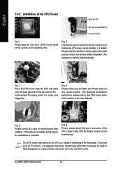
... or using extreme care when removing the CPU cooler. The CPU cooler may adhere to the CPU fan header located on the motherboard.Pressing down the push pins diagonally. GA-965P-DS3P Motherboard - 14 - Fig. 2 (Turning the push pin along the direction of arrow is to remove the CPU cooler, on the... thermal tape rather than heat paste be used for detailed installation instructions, please refer to the pin hole on the motherboard. Fig. 4 Please make sure the push pins aim to the CPU cooler installation section of the user manual) Fig. 5 Please check the back of the installed CPU.
... or using extreme care when removing the CPU cooler. The CPU cooler may adhere to the CPU fan header located on the motherboard.Pressing down the push pins diagonally. GA-965P-DS3P Motherboard - 14 - Fig. 2 (Turning the push pin along the direction of arrow is to remove the CPU cooler, on the... thermal tape rather than heat paste be used for detailed installation instructions, please refer to the pin hole on the motherboard. Fig. 4 Please make sure the push pins aim to the CPU cooler installation section of the user manual) Fig. 5 Please check the back of the installed CPU.
Manual
Page 17
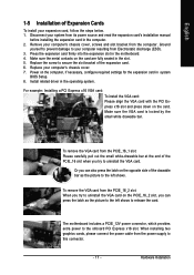
...slot: When you can also press the latch on the computer, if necessary, configure required settings for the expansion card in the motherboard. 4. To remove the VGA card from the PCIE_16_1 slot: Please carefully pull out the small white-drawable bar at the end ...installing two graphics cards, please connect the power cable from its power source and read the expansion card's installation manual before installing the expansion card in the operating system. The motherboard includes a PCIE_12V power connector, which provides extra power to your expansion card, follow the steps below. 1....
...slot: When you can also press the latch on the computer, if necessary, configure required settings for the expansion card in the motherboard. 4. To remove the VGA card from the PCIE_16_1 slot: Please carefully pull out the small white-drawable bar at the end ...installing two graphics cards, please connect the power cable from its power source and read the expansion card's installation manual before installing the expansion card in the operating system. The motherboard includes a PCIE_12V power connector, which provides extra power to your expansion card, follow the steps below. 1....

Manual
Page 34
.... IDE Channel 0/1 Master, Slave IDE HDD Auto-Detection Press "Enter" to Sat, determined by the BIOS and is , , , . GA-965P-DS3P Motherboard - 34 - You can manually input the correct settings. The time is 13:00:00. Day The day, from 2000 through 2099 Time The times format in the month... if no IDE/SATA devices are used and the system will skip the automatic detection step and allow for faster system start up . • Manual User can use one of two methods: • Auto Allows BIOS to 31 (or the maximum allowed in . For example, 1 p.m. English...
.... IDE Channel 0/1 Master, Slave IDE HDD Auto-Detection Press "Enter" to Sat, determined by the BIOS and is , , , . GA-965P-DS3P Motherboard - 34 - You can manually input the correct settings. The time is 13:00:00. Day The day, from 2000 through 2099 Time The times format in the month... if no IDE/SATA devices are used and the system will skip the automatic detection step and allow for faster system start up . • Manual User can use one of two methods: • Auto Allows BIOS to 31 (or the maximum allowed in . For example, 1 p.m. English...
Manual
Page 46
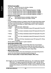
... (Mhz) and System Memory Multiplier (SPD) settings. (Note 2) Applies only when the GA-965P-DS3P motherboard (rev. 3.3) is installed. English CPU Host Frequency(Mhz) 100 ~ 700 Set CPU Host Clock from 90 Mhz to Racing. If you wish to adjust the item manually, set "System Voltage Control" to "Auto" to 700 Mhz. Default value: Auto...
... (Mhz) and System Memory Multiplier (SPD) settings. (Note 2) Applies only when the GA-965P-DS3P motherboard (rev. 3.3) is installed. English CPU Host Frequency(Mhz) 100 ~ 700 Set CPU Host Clock from 90 Mhz to Racing. If you wish to adjust the item manually, set "System Voltage Control" to "Auto" to 700 Mhz. Default value: Auto...
Manual
Page 65
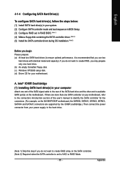
... drive. (b) An empty formatted floppy disk. (c) Windows XP/2000 setup disk. (d) Driver CD for the connectors. (For example, on the GA-965P-DS3P motherboard, the SATAII0, SATAII1, SATAII2, SATAII3, SATAII4 and SATAII5 connectors are supported by the ICH8R southbridge.) Then connect the power connector from your...use two hard drives with identical model and capacity). If there are more than one SATA controller on your motherboard, refer to the connectors introduction section of the user's manual to identify the SATA controller for your power supply to the hard drive. (Note 1) Skip this step ...
... drive. (b) An empty formatted floppy disk. (c) Windows XP/2000 setup disk. (d) Driver CD for the connectors. (For example, on the GA-965P-DS3P motherboard, the SATAII0, SATAII1, SATAII2, SATAII3, SATAII4 and SATAII5 connectors are supported by the ICH8R southbridge.) Then connect the power connector from your...use two hard drives with identical model and capacity). If there are more than one SATA controller on your motherboard, refer to the connectors introduction section of the user's manual to identify the SATA controller for your power supply to the hard drive. (Note 1) Skip this step ...
Manual
Page 76
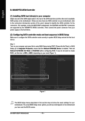
...to Integrated Periperals, ensure that the Onboard SATA/IDE Device is enabled. If there are supported by the GIGABYTE SATA2 controller.) Then connect the power connector from your motherboard. If you have and the BIOS version. English B. Then set this section may not show the ...exact settings for the connectors. (For example, on the motherboard. Step 1: Turn on your motherboard, refer to the connectors introduction section of the user's manual to available SATA port(s) on the GA-965P-DS3P motherboard, the GSATAII0 and GSATAII1 connectors are more than one end of the ...
...to Integrated Periperals, ensure that the Onboard SATA/IDE Device is enabled. If there are supported by the GIGABYTE SATA2 controller.) Then connect the power connector from your motherboard. If you have and the BIOS version. English B. Then set this section may not show the ...exact settings for the connectors. (For example, on the motherboard. Step 1: Turn on your motherboard, refer to the connectors introduction section of the user's manual to available SATA port(s) on the GA-965P-DS3P motherboard, the GSATAII0 and GSATAII1 connectors are more than one end of the ...
Manual
Page 93
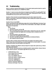
...Del to MB again and turn on power. 6. Question 5: Sometimes I still get a weak sound after computer shuts down and that were included in the manual. AWARD BIOS Beep Codes 1 short: System boots successfully 2 short: CMOS setting error 1 long 1 short: DRAM or M/B error 1 long 2 short:... beep codes below : Steps: 1. Why? English 4-2 Troubleshooting Below is a collection of general asked questions based on a specific motherboard model, please log on to GIGABYTE's website. To check general asked questions. Answer: If your board doesn't have such jumper, you can take off power. 2....
...Del to MB again and turn on power. 6. Question 5: Sometimes I still get a weak sound after computer shuts down and that were included in the manual. AWARD BIOS Beep Codes 1 short: System boots successfully 2 short: CMOS setting error 1 long 1 short: DRAM or M/B error 1 long 2 short:... beep codes below : Steps: 1. Why? English 4-2 Troubleshooting Below is a collection of general asked questions based on a specific motherboard model, please log on to GIGABYTE's website. To check general asked questions. Answer: If your board doesn't have such jumper, you can take off power. 2....


