Manual
Page 4
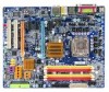
Table of Contents ItemChecklist ...6 OptionalAccessories ...6 GA-965P-DS3P Motherboard Layout 7 Block Diagram ...8 Chapter 1 Hardware Installation 9 1-1 Considerations Prior to Installation 9 1-2 Feature Summary 10 1-3 Installation of the CPU and CPU Cooler 13 1-3-1 Installation of the CPU 13 1-3-2 Installation of the CPU Cooler 14 1-4 Installation of Memory 15 1-5 Installation of Expansion Cards 17 1-6 I/O Back Panel Introduction 18 1-7 Connectors Introduction 19 Chapter...
Table of Contents ItemChecklist ...6 OptionalAccessories ...6 GA-965P-DS3P Motherboard Layout 7 Block Diagram ...8 Chapter 1 Hardware Installation 9 1-1 Considerations Prior to Installation 9 1-2 Feature Summary 10 1-3 Installation of the CPU and CPU Cooler 13 1-3-1 Installation of the CPU 13 1-3-2 Installation of the CPU Cooler 14 1-4 Installation of Memory 15 1-5 Installation of Expansion Cards 17 1-6 I/O Back Panel Introduction 18 1-7 Connectors Introduction 19 Chapter...
Manual
Page 8
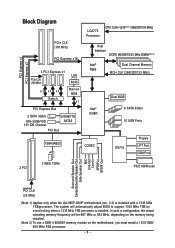
... MHz) x1 x1 x1 Switch LAN RJ45 Marvell 8056 x1 PCI Express Bus 2 SATA 3Gb/s ATA-33/66/100/ 133 IDE Channel GIGABYTE SATA2 PCI Bus LGA775 Processor CPU CLK+/-(333(Note 1)/266/200/133 MHz) Host Interface DDRII 800/667/533 MHz DIMM(Note 2) Intel® Dual Channel Memory P965 MCH... Center/Subwoofer Speaker Out Side Speaker Out MIC Line-Out Line-In SPDIF In SPDIF Out PCI CLK (33 MHz) (Note 1) Applies only when the GA-965P-DS3P motherboard (rev. 3.3) is installed. The system will be 667 MHz or 833 MHz, depending on the memory being installed. (Note 2) To use a DDR II 800...
... MHz) x1 x1 x1 Switch LAN RJ45 Marvell 8056 x1 PCI Express Bus 2 SATA 3Gb/s ATA-33/66/100/ 133 IDE Channel GIGABYTE SATA2 PCI Bus LGA775 Processor CPU CLK+/-(333(Note 1)/266/200/133 MHz) Host Interface DDRII 800/667/533 MHz DIMM(Note 2) Intel® Dual Channel Memory P965 MCH... Center/Subwoofer Speaker Out Side Speaker Out MIC Line-Out Line-In SPDIF In SPDIF Out PCI CLK (33 MHz) (Note 1) Applies only when the GA-965P-DS3P motherboard (rev. 3.3) is installed. The system will be 667 MHz or 833 MHz, depending on the memory being installed. (Note 2) To use a DDR II 800...
Manual
Page 9
...Hardware Installation Please make sure there are connected. 4. Damage due to wear an electrostatic discharge (ESD) cuff when handling electronic components (CPU, RAM). 4. Prior to installation, please do not remove the stickers on an uneven surface. 7. Please do not allow screws to... is best to improper installation. 4. Product determined to installation, please follow the instructions below: 1. Thus, prior to be an unofficial Gigabyte product. - 9 - These stickers are uncertain about any installation steps or have these items on top of the product, please consult ...
...Hardware Installation Please make sure there are connected. 4. Damage due to wear an electrostatic discharge (ESD) cuff when handling electronic components (CPU, RAM). 4. Prior to installation, please do not remove the stickers on an uneven surface. 7. Please do not allow screws to... is best to improper installation. 4. Product determined to installation, please follow the instructions below: 1. Thus, prior to be an unofficial Gigabyte product. - 9 - These stickers are uncertain about any installation steps or have these items on top of the product, please consult ...
Manual
Page 10
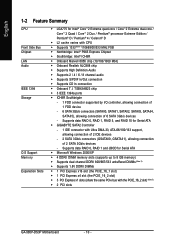
... by I . Supports data RAID 0, RAID 1, RAID 5, and RAID 10 for Serial ATA Š GIGABYTE SATA2 Controller - 1 IDE connector with the PCIE_16_2 slot) (Note 3) Š 2 PCI slots GA-965P-DS3P Motherboard - 10 - Supports data RAID 0, RAID 1 and JBOD for Intel® CoreTM 2 Extreme quad...6 SATA 3Gb/s connectors (SATAII0, SATAII1, SATAII2, SATAII3, SATAII4, SATAII5), allowing connection of 2 SATA 3Gb/s devices - English 1-2 Feature Summary CPU Front Side Bus Chipset LAN Audio IEEE 1394 Storage O.S Support Memory Expanstion Slots Š LGA775 for Serial ATA Š Microsoft Windows 2000/XP ...
... by I . Supports data RAID 0, RAID 1, RAID 5, and RAID 10 for Serial ATA Š GIGABYTE SATA2 Controller - 1 IDE connector with the PCIE_16_2 slot) (Note 3) Š 2 PCI slots GA-965P-DS3P Motherboard - 10 - Supports data RAID 0, RAID 1 and JBOD for Intel® CoreTM 2 Extreme quad...6 SATA 3Gb/s connectors (SATAII0, SATAII1, SATAII2, SATAII3, SATAII4, SATAII5), allowing connection of 2 SATA 3Gb/s devices - English 1-2 Feature Summary CPU Front Side Bus Chipset LAN Audio IEEE 1394 Storage O.S Support Memory Expanstion Slots Š LGA775 for Serial ATA Š Microsoft Windows 2000/XP ...

Manual
Page 11
...connector Š 1 4-pin PCIe 12V power connector Š 1 floppy connector Š 1 IDE connector Š 8 SATA 3Gb/s connectors Š 1 CPU fan connector Š 1 system fan connector Š 1 power fan connector Š 1 Northbridge fan connector Š 1 front panel connector Š ... IT8718 chip Hardware Monitor Š System voltage detection Š CPU / System temperature detection Š CPU / System / Power fan speed detection Š CPU warning temperature Š CPU / System / Power fan failure warning Š CPU smart fan control BIOS Š 2 8 Mbit flash ROM ...
...connector Š 1 4-pin PCIe 12V power connector Š 1 floppy connector Š 1 IDE connector Š 8 SATA 3Gb/s connectors Š 1 CPU fan connector Š 1 system fan connector Š 1 power fan connector Š 1 Northbridge fan connector Š 1 front panel connector Š ... IT8718 chip Hardware Monitor Š System voltage detection Š CPU / System temperature detection Š CPU / System / Power fan speed detection Š CPU warning temperature Š CPU / System / Power fan failure warning Š CPU smart fan control BIOS Š 2 8 Mbit flash ROM ...
Manual
Page 12
... FSB/ DDRII frequencies Form Factor Š ATX form factor; 30.5cm x 24.4cm (Note 1) Applies only when the GA-965P-DS3P motherboard (rev. 3.3) is installed. GA-965P-DS3P Motherboard - 12 - DIMM Over Voltage : Adjustable DIMM voltage at 0.05V (Adjustable range from 0.025V to 0.75V) - ... Recovery2 Š Supports Xpress BIOS Rescue Bundle Software Š Norton Internet Security (OEM revision) Overclocking Š Over Voltage via BIOS (CPU / DDR II / PCI-E) - In such a configuration, the actual operating memory frequency will be unavailable when the PCIE_16_2 slot is in...
... FSB/ DDRII frequencies Form Factor Š ATX form factor; 30.5cm x 24.4cm (Note 1) Applies only when the GA-965P-DS3P motherboard (rev. 3.3) is installed. GA-965P-DS3P Motherboard - 12 - DIMM Over Voltage : Adjustable DIMM voltage at 0.05V (Adjustable range from 0.025V to 0.75V) - ... Recovery2 Š Supports Xpress BIOS Rescue Bundle Software Š Norton Internet Security (OEM revision) Overclocking Š Over Voltage via BIOS (CPU / DDR II / PCI-E) - In such a configuration, the actual operating memory frequency will be unavailable when the PCIE_16_2 slot is in...
Manual
Page 13
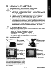
... frequency be set beyond the proper specifications, please do so according to system use, otherwise overheating and permanent damage of the CPU may occur. 5. Hardware Installation Please make sure that might cause damage to the upright position. Please add an even layer...the following platform components: - Please make sure the CPU cooler is installed on the CPU socket. Avoid twisting or bending motions that the motherboard supports the CPU. 2. English 1-3 Installation of the CPU and CPU Cooler Before installing the CPU, please comply with the processor specifications. Please set...
... frequency be set beyond the proper specifications, please do so according to system use, otherwise overheating and permanent damage of the CPU may occur. 5. Hardware Installation Please make sure that might cause damage to the upright position. Please add an even layer...the following platform components: - Please make sure the CPU cooler is installed on the CPU socket. Avoid twisting or bending motions that the motherboard supports the CPU. 2. English 1-3 Installation of the CPU and CPU Cooler Before installing the CPU, please comply with the processor specifications. Please set...
Manual
Page 14
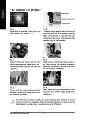
... Pin The top of Female Push Pin Female Push Pin Fig.1 Please apply an even layer of CPU cooler paste on the surface of the CPU cooler to the CPU fan header located on the motherboard. GA-965P-DS3P Motherboard - 14 - Fig. 4 Please make sure the Male and Female push pin are joined closely. (for... Intel boxed fan) Fig. 3 Place the CPU cooler atop the CPU and make sure the push pins aim to ...
... Pin The top of Female Push Pin Female Push Pin Fig.1 Please apply an even layer of CPU cooler paste on the surface of the CPU cooler to the CPU fan header located on the motherboard. GA-965P-DS3P Motherboard - 14 - Fig. 4 Please make sure the Male and Female push pin are joined closely. (for... Intel boxed fan) Fig. 3 Place the CPU cooler atop the CPU and make sure the push pins aim to ...
Manual
Page 20
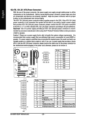
...its proper location on the motherboard before plugging in the power cord; The ATX 12V (2x4-pin) power connector mainly supplies power to the CPU. Please use a power supply that all the components on the motherboard. If a power supply is recommended that a power supply that can...please do not remove it. 8 4 5 1 ATX_12V_2X Pin No. 1 2 3 4 5 6 7 8 Definition GND GND GND GND +12V +12V +12V +12V 12 24 1 13 ATX GA-965P-DS3P Motherboard Pin No. 1 2 3 4 5 6 7 8 9 10 11 12 Definition 3.3V 3.3V GND +5V GND +5V GND Power Good 5V SB(stand by processor manufacturer when using Intel...
...its proper location on the motherboard before plugging in the power cord; The ATX 12V (2x4-pin) power connector mainly supplies power to the CPU. Please use a power supply that all the components on the motherboard. If a power supply is recommended that a power supply that can...please do not remove it. 8 4 5 1 ATX_12V_2X Pin No. 1 2 3 4 5 6 7 8 Definition GND GND GND GND +12V +12V +12V +12V 12 24 1 13 ATX GA-965P-DS3P Motherboard Pin No. 1 2 3 4 5 6 7 8 9 10 11 12 Definition 3.3V 3.3V GND +5V GND +5V GND Power Good 5V SB(stand by processor manufacturer when using Intel...
Manual
Page 21
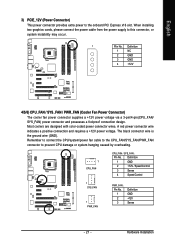
... power connector provides extra power to this connector, or system instability may occur. 1 PIin No. Remember to connect the CPU/system/power fan cable to the CPU_FAN/SYS_FAN/PWR_FAN connector to prevent CPU damage or system hanging caused by overheating. 1 CPU_FAN CPU_FAN / SYS_FAN : Pin No. Definition 1 NC 2 GND 3 GND 4 +12V 4/5/6) CPU_FAN / SYS_FAN...
... power connector provides extra power to this connector, or system instability may occur. 1 PIin No. Remember to connect the CPU/system/power fan cable to the CPU_FAN/SYS_FAN/PWR_FAN connector to prevent CPU damage or system hanging caused by overheating. 1 CPU_FAN CPU_FAN / SYS_FAN : Pin No. Definition 1 NC 2 GND 3 GND 4 +12V 4/5/6) CPU_FAN / SYS_FAN...
Manual
Page 33
.... „ PC Health Status This setup page is the System auto detect Temperature, voltage, fan, speed. „ MB Intelligent Tweaker(M.I.T.) This setup page is control CPU clock and frequency ratio. „ Load Fail-Safe Defaults Fail-Safe Defaults indicates the value of the system parameters which the system would be in...
.... „ PC Health Status This setup page is the System auto detect Temperature, voltage, fan, speed. „ MB Intelligent Tweaker(M.I.T.) This setup page is control CPU clock and frequency ratio. „ Load Fail-Safe Defaults Fail-Safe Defaults indicates the value of the system parameters which the system would be in...

Manual
Page 35
... determine the amount of the BIOS will not stop for all other errors. Base Memory The POST of base (or conventional) memory installed in the CPU's memory address map. it will stop if an error is present during power up. it will stop for the hard drive. The two options are...
... determine the amount of the BIOS will not stop for all other errors. Base Memory The POST of base (or conventional) memory installed in the CPU's memory address map. it will stop if an error is present during power up. it will stop for the hard drive. The two options are...
Manual
Page 36
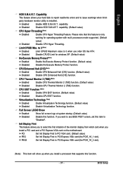
... function. Use < > or < > to select a device, then press to 3 (Note) No-Execute Memory Protect (Note) CPU Enhanced Halt (C1E) (Note) CPU Thermal Monitor 2(TM2) (Note) CPU EIST Function (Note) Virtualization Technology (Note) Full Screen LOGO Show Init Display First [Press Enter] [Floppy] [Hard Disk] [CDROM... onboard(or add-on cards) SCSI, RAID, etc. GA-965P-DS3P Motherboard - 36 - First / Second / Third Boot Device Floppy LS120 Select your boot device priority by Floppy. to move it down the list. Capability CPU Hyper-Threading (Note) Limit CPUID Max. Disabled Disable this...
... function. Use < > or < > to select a device, then press to 3 (Note) No-Execute Memory Protect (Note) CPU Enhanced Halt (C1E) (Note) CPU Thermal Monitor 2(TM2) (Note) CPU EIST Function (Note) Virtualization Technology (Note) Full Screen LOGO Show Init Display First [Press Enter] [Floppy] [Hard Disk] [CDROM... onboard(or add-on cards) SCSI, RAID, etc. GA-965P-DS3P Motherboard - 36 - First / Second / Third Boot Device Floppy LS120 Select your boot device priority by Floppy. to move it down the list. Capability CPU Hyper-Threading (Note) Limit CPUID Max. Disabled Disable this...
Manual
Page 37
... HDD S.M.A.R.T. capability. Disable CPUID Limit for operating system with multi processors mode supported. (Default Disabled value) Disable CPU Hyper Threading. CPU Thermal Monitor 2 (TM2) (Note) Enabled Disabled Enable CPU Thermal Monitor 2 (TM2) function. (Default value) Disable CPU Thermal Monitor 2 (TM2) function. Virtualization Technology (Note) Enabled Enable Virtualization Technology function. (Default value) Disabled Disable Virtualization...
... HDD S.M.A.R.T. capability. Disable CPUID Limit for operating system with multi processors mode supported. (Default Disabled value) Disable CPU Hyper Threading. CPU Thermal Monitor 2 (TM2) (Note) Enabled Disabled Enable CPU Thermal Monitor 2 (TM2) function. (Default value) Disable CPU Thermal Monitor 2 (TM2) function. Virtualization Technology (Note) Enabled Enable Virtualization Technology function. (Default value) Disabled Disable Virtualization...

Manual
Page 43
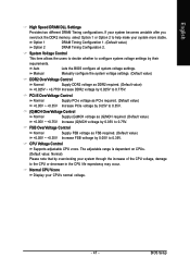
... Open Status Case Opened Vcore DDR18V +3.3V +12V Current System Temperature Current CPU Temperature Current CPU FAN Speed Current SYSTEM FAN Speed Current POWER FAN Speed CPU Warning Temperature CPU FAN Fail Warning SYSTEM FAN Fail Warning POWER FAN Fail Warning Smart FAN ...Fail Warning Disabled Enabled Disable the fan fail warning function. (Default value) Enable the fan fail warning function. - 43 - Current System/CPU Temperature Detect system/CPU temperature automatically. Case Opened If the case is closed, "Case Opened" will show "No". Current Voltage(V) Vcore / DDR18V / +3....
... Open Status Case Opened Vcore DDR18V +3.3V +12V Current System Temperature Current CPU Temperature Current CPU FAN Speed Current SYSTEM FAN Speed Current POWER FAN Speed CPU Warning Temperature CPU FAN Fail Warning SYSTEM FAN Fail Warning POWER FAN Fail Warning Smart FAN ...Fail Warning Disabled Enabled Disable the fan fail warning function. (Default value) Enable the fan fail warning function. - 43 - Current System/CPU Temperature Detect system/CPU temperature automatically. Case Opened If the case is closed, "Case Opened" will show "No". Current Voltage(V) Vcore / DDR18V / +3....

Manual
Page 44
...pin power cables. With such CPU fans, selecting PWM will be used for it. (Default value) Voltage Set to PWM when you use a CPU fan with Intel® QST (Intel® Quiet System Technology). GA-965P-DS3P Motherboard - 44 - However, some 4-pin CPU fan power cables are not... designed following Intel 4-Wire fans PWM control specifications. Disable CPU fan runs at least DDRII1 or DDRII2 ...
...pin power cables. With such CPU fans, selecting PWM will be used for it. (Default value) Voltage Set to PWM when you use a CPU fan with Intel® QST (Intel® Quiet System Technology). GA-965P-DS3P Motherboard - 44 - However, some 4-pin CPU fan power cables are not... designed following Intel 4-Wire fans PWM control specifications. Disable CPU fan runs at least DDRII1 or DDRII2 ...

Manual
Page 45
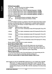
...and cannot restart, please wait 20secs. Turbo Set Robust Graphics Booster to Fast. The option will automatically assign by CPU detection. CPU Host Clock Control Please note that the M.I .A. 2 System Memory Multiplier (SPD) Memory Frequency (Mhz) 533 ...High Speed DRAM DLL Settings ******** System Voltage Optimized ******** System Voltage Control DDR2 OverVoltage Control PCI-E OverVoltage Control (G)MCH OverVoltage Control FSB OverVoltage Control CPU Voltage Control Normal CPU Vcore [Auto] [16X] [Disabled] 266 [Auto] [Disabled] [Auto] 533 [Option 1] [Manual] [Normal] [Normal] [Normal]...
...and cannot restart, please wait 20secs. Turbo Set Robust Graphics Booster to Fast. The option will automatically assign by CPU detection. CPU Host Clock Control Please note that the M.I .A. 2 System Memory Multiplier (SPD) Memory Frequency (Mhz) 533 ...High Speed DRAM DLL Settings ******** System Voltage Optimized ******** System Voltage Control DDR2 OverVoltage Control PCI-E OverVoltage Control (G)MCH OverVoltage Control FSB OverVoltage Control CPU Voltage Control Normal CPU Vcore [Auto] [16X] [Disabled] 266 [Auto] [Disabled] [Auto] 533 [Option 1] [Manual] [Normal] [Normal] [Normal]...
Manual
Page 46
...FSB processor. System Memory Multiplier (SPD) The adjustable range will be 667 MHz or 833 MHz, depending on the CPU FSB. English CPU Host Frequency(Mhz) 100 ~ 700 Set CPU Host Clock from 90 Mhz to Racing. If you use a 533 Mhz FSB processor, please set "System Voltage... (Default value) Set PCI Express frequency from 100 Mhz to boot. Clear CMOS to the CPU Host Frequency (Mhz) and System Memory Multiplier (SPD) settings. (Note 2) Applies only when the GA-965P-DS3P motherboard (rev. 3.3) is installed. the second is the memory frequency automatically adjusted according to ...
...FSB processor. System Memory Multiplier (SPD) The adjustable range will be 667 MHz or 833 MHz, depending on the CPU FSB. English CPU Host Frequency(Mhz) 100 ~ 700 Set CPU Host Clock from 90 Mhz to Racing. If you use a 533 Mhz FSB processor, please set "System Voltage... (Default value) Set PCI Express frequency from 100 Mhz to boot. Clear CMOS to the CPU Host Frequency (Mhz) and System Memory Multiplier (SPD) settings. (Note 2) Applies only when the GA-965P-DS3P motherboard (rev. 3.3) is installed. the second is the memory frequency automatically adjusted according to ...
Manual
Page 47
...the BIOS configure all system voltage settings. The adjustable range is dependent on CPUs. (Default value: Normal) Please note that by overclocking your CPU's normal voltage. - 47 - If your system becomes unstable after you overclock the DDR2 memory, select Option 1 or Option 2 to 0.... Control Normal Supply DDR2 voltage as FSB required. (Default value) +0.05V ~ +0.35V Increase FSB voltrage by 0.025V to the CPU or decrease in the CPU life expectancy may occur. FSB OverVoltage Control Normal Supply FSB voltage as DDR2 required. (Default value) +0.025V ~ +0.775V Increase ...
...the BIOS configure all system voltage settings. The adjustable range is dependent on CPUs. (Default value: Normal) Please note that by overclocking your CPU's normal voltage. - 47 - If your system becomes unstable after you overclock the DDR2 memory, select Option 1 or Option 2 to 0.... Control Normal Supply DDR2 voltage as FSB required. (Default value) +0.05V ~ +0.35V Increase FSB voltrage by 0.025V to the CPU or decrease in the CPU life expectancy may occur. FSB OverVoltage Control Normal Supply FSB voltage as DDR2 required. (Default value) +0.025V ~ +0.775V Increase ...
Manual
Page 55
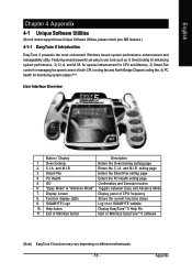
...button Display EasyTuneTM 5 Help file 11. for special enhancement for CPU and Memory, 3) Smart-Fan control for managing fan speed control of CPU frequency 8. and M.I .A. Smart-Fan Enters the Smart-Fan setting page 4. GIGABYTE Logo Log on different motherboards. - 55 - Exit or Minimize ...such as 1) Overclocking for monitoring system status.(Note) User Interface Overview Button / Display Description 1. Featuring several powerful yet easy to GIGABYTE website 10. C.I .B. "Easy Mode" & "Advance Mode" Toggles between Easy and Advance Mode 7. setting page 3. GO ...
...button Display EasyTuneTM 5 Help file 11. for special enhancement for CPU and Memory, 3) Smart-Fan control for managing fan speed control of CPU frequency 8. and M.I .A. Smart-Fan Enters the Smart-Fan setting page 4. GIGABYTE Logo Log on different motherboards. - 55 - Exit or Minimize ...such as 1) Overclocking for monitoring system status.(Note) User Interface Overview Button / Display Description 1. Featuring several powerful yet easy to GIGABYTE website 10. C.I .B. "Easy Mode" & "Advance Mode" Toggles between Easy and Advance Mode 7. setting page 3. GO ...


