Manual
Page 4
...GA-965P-DS3P Motherboard Layout 7 Block Diagram ...8 Chapter 1 Hardware Installation 9 1-1 Considerations Prior to Installation 9 1-2 Feature Summary 10 1-3 Installation of the CPU and CPU Cooler 13 1-3-1 Installation of the CPU 13 1-3-2 Installation of the CPU Cooler 14 1-4 Installation of Memory 15 1-5 Installation of Expansion Cards 17 1-6 I/O Back Panel Introduction 18 1-7 Connectors Introduction 19 Chapter 2 BIOS... Setup 31 The Main Menu (For example: BIOS Ver. : F4a 32 2-1 Standard CMOS Features 34 2-2 Advanced BIOS Features 36 2-3 ...
...GA-965P-DS3P Motherboard Layout 7 Block Diagram ...8 Chapter 1 Hardware Installation 9 1-1 Considerations Prior to Installation 9 1-2 Feature Summary 10 1-3 Installation of the CPU and CPU Cooler 13 1-3-1 Installation of the CPU 13 1-3-2 Installation of the CPU Cooler 14 1-4 Installation of Memory 15 1-5 Installation of Expansion Cards 17 1-6 I/O Back Panel Introduction 18 1-7 Connectors Introduction 19 Chapter 2 BIOS... Setup 31 The Main Menu (For example: BIOS Ver. : F4a 32 2-1 Standard CMOS Features 34 2-2 Advanced BIOS Features 36 2-3 ...
Manual
Page 5
Intel® ICH8R Southbridge 65 B. Channel Audio Function Introduction 88 4-2 Troubleshooting 93 - 5 - Chapter 3 Drivers Installation 51 3-1 Install Chipset Drivers 51 3-2 SoftwareApplications 52 3-3 Driver CD Information 52 3-4 Hardware Information 53 3-5 Contact Us ...53 Chapter 4 Appendix 55 4-1 Unique Software Utilities 55 4-1-1 EasyTune 5 Introduction 55 4-1-2 Xpress Recovery2 Introduction 56 4-1-3 Flash BIOS Method Introduction 58 4-1-4 Configuring SATA Hard Drive(s 65 A. GIGABYTE SATA2 Controller 76 4-1-5 2- / 4- / 6- / 8-
Intel® ICH8R Southbridge 65 B. Channel Audio Function Introduction 88 4-2 Troubleshooting 93 - 5 - Chapter 3 Drivers Installation 51 3-1 Install Chipset Drivers 51 3-2 SoftwareApplications 52 3-3 Driver CD Information 52 3-4 Hardware Information 53 3-5 Contact Us ...53 Chapter 4 Appendix 55 4-1 Unique Software Utilities 55 4-1-1 EasyTune 5 Introduction 55 4-1-2 Xpress Recovery2 Introduction 56 4-1-3 Flash BIOS Method Introduction 58 4-1-4 Configuring SATA Hard Drive(s 65 A. GIGABYTE SATA2 Controller 76 4-1-5 2- / 4- / 6- / 8-
Manual
Page 7
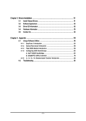
GA-965P-DS3P Motherboard Layout KB_MS COAXIAL OPTICAL ATX_12V_2X LGA775 PWR_FAN PCIE_12V ATX COM LPT 1394 USB GA-965P-DS3P LAN USB AUDIO BATTERY CPU_FAN CLR_CMOS Intel® P965 F_AUDIO PCIE_1 FDD Marvell 8053 PCIE_16_1 NB_FAN DDRII1 DDRII2 DDRII3 DDRII4 PCIE_2 CODEC PCIE_3 CD_IN PCIE_16_2 PCI1 IT8718 PCI2 SPDIF_IN BACKUP MAIN BIOS BIOS CI TSB43AB23 SYS_FAN F1_1394 SATAII0 Intel® ICH8R SATAII4 SATAII1 SATAII2 SATAII5 SATAII3 GIGABYTE SATA2 IDE GSATAII1 GSATAII0 F_USB1 F_USB2 F_USB3 PWR_LED F_PANEL F2_1394 - 7 -
GA-965P-DS3P Motherboard Layout KB_MS COAXIAL OPTICAL ATX_12V_2X LGA775 PWR_FAN PCIE_12V ATX COM LPT 1394 USB GA-965P-DS3P LAN USB AUDIO BATTERY CPU_FAN CLR_CMOS Intel® P965 F_AUDIO PCIE_1 FDD Marvell 8053 PCIE_16_1 NB_FAN DDRII1 DDRII2 DDRII3 DDRII4 PCIE_2 CODEC PCIE_3 CD_IN PCIE_16_2 PCI1 IT8718 PCI2 SPDIF_IN BACKUP MAIN BIOS BIOS CI TSB43AB23 SYS_FAN F1_1394 SATAII0 Intel® ICH8R SATAII4 SATAII1 SATAII2 SATAII5 SATAII3 GIGABYTE SATA2 IDE GSATAII1 GSATAII0 F_USB1 F_USB2 F_USB3 PWR_LED F_PANEL F2_1394 - 7 -
Manual
Page 8
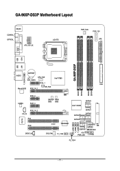
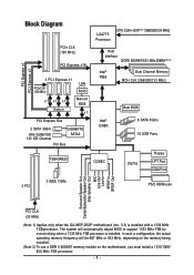
... PCIe CLK (100 MHz) x1 x1 x1 Switch LAN RJ45 Marvell 8056 x1 PCI Express Bus 2 SATA 3Gb/s ATA-33/66/100/ 133 IDE Channel GIGABYTE SATA2 PCI Bus LGA775 Processor CPU CLK+/-(333(Note 1)/266/200/133 MHz) Host Interface DDRII 800/667/533 MHz DIMM(Note 2) Intel® Dual...; ICH8R Dual BIOS 6 SATA 3Gb/s 10 USB Ports TSB43AB23 CODEC IT8718 Floppy LPT Port COM Port 2 PCI 3 IEEE 1394a PS/2 KB/Mouse Surround Speaker Out Center/Subwoofer Speaker Out Side Speaker Out MIC Line-Out Line-In SPDIF In SPDIF Out PCI CLK (33 MHz) (Note 1) Applies only when the GA-965P-DS3P motherboard...
... PCIe CLK (100 MHz) x1 x1 x1 Switch LAN RJ45 Marvell 8056 x1 PCI Express Bus 2 SATA 3Gb/s ATA-33/66/100/ 133 IDE Channel GIGABYTE SATA2 PCI Bus LGA775 Processor CPU CLK+/-(333(Note 1)/266/200/133 MHz) Host Interface DDRII 800/667/533 MHz DIMM(Note 2) Intel® Dual...; ICH8R Dual BIOS 6 SATA 3Gb/s 10 USB Ports TSB43AB23 CODEC IT8718 Floppy LPT Port COM Port 2 PCI 3 IEEE 1394a PS/2 KB/Mouse Surround Speaker Out Center/Subwoofer Speaker Out Side Speaker Out MIC Line-Out Line-In SPDIF In SPDIF Out PCI CLK (33 MHz) (Note 1) Applies only when the GA-965P-DS3P motherboard...

Manual
Page 11
... temperature detection Š CPU / System / Power fan speed detection Š CPU warning temperature Š CPU / System / Power fan failure warning Š CPU smart fan control BIOS Š 2 8 Mbit flash ROM Š Use of licensed AWARD...
... temperature detection Š CPU / System / Power fan speed detection Š CPU warning temperature Š CPU / System / Power fan failure warning Š CPU smart fan control BIOS Š 2 8 Mbit flash ROM Š Use of licensed AWARD...
Manual
Page 12
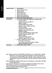
.../1066/ 800 MHz FSB processor. (Note 3) The three PCI Express x1 slots will automatically adjust BIOS to 0.75V) - Adjustable FSB/ DDRII frequencies Form Factor Š ATX form factor; 30.5cm x 24.4cm (Note 1) Applies only when the GA-965P-DS3P motherboard (rev. 3.3) is dependent on different motherboards. (Note 5) The adjustable range is installed with...
.../1066/ 800 MHz FSB processor. (Note 3) The three PCI Express x1 slots will automatically adjust BIOS to 0.75V) - Adjustable FSB/ DDRII frequencies Form Factor Š ATX form factor; 30.5cm x 24.4cm (Note 1) Applies only when the GA-965P-DS3P motherboard (rev. 3.3) is dependent on different motherboards. (Note 5) The adjustable range is installed with...
Manual
Page 13
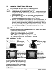
... has optimizations for HT Technology 1-3-1 Installation of the CPU socket. If you install the CPU in the wrong direction, the CPU will not insert properly. BIOS: A BIOS that might cause damage to system use, otherwise overheating and permanent damage of the following conditions: 1. Align the indented corner of the CPU with the...
... has optimizations for HT Technology 1-3-1 Installation of the CPU socket. If you install the CPU in the wrong direction, the CPU will not insert properly. BIOS: A BIOS that might cause damage to system use, otherwise overheating and permanent damage of the following conditions: 1. Align the indented corner of the CPU with the...
Manual
Page 15
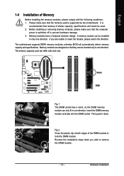
..., please make sure that memory of similar capacity, specifications and brand be used is supported by the motherboard. The motherboard supports DDRII memory modules, whereby BIOS will automatically detect memory capacity and specifications. The memory capacity used can be inserted only in one direction. Then push it down. If you wish...
..., please make sure that memory of similar capacity, specifications and brand be used is supported by the motherboard. The motherboard supports DDRII memory modules, whereby BIOS will automatically detect memory capacity and specifications. The memory capacity used can be inserted only in one direction. Then push it down. If you wish...
Manual
Page 17
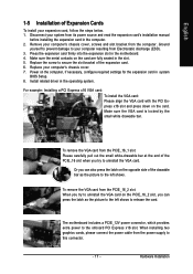
... prevent damage to this connector. - 17 - Make sure the metal contacts on the computer, if necessary, configure required settings for the expansion card in system BIOS Setup. 8. English 1-5 Installation of Expansion Cards To install your system from its power source and read the expansion card's installation manual before installing the expansion...
... prevent damage to this connector. - 17 - Make sure the metal contacts on the computer, if necessary, configure required settings for the expansion card in system BIOS Setup. 8. English 1-5 Installation of Expansion Cards To install your system from its power source and read the expansion card's installation manual before installing the expansion...
Manual
Page 23
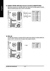
Please refer to the BIOS setting for information on one IDE cable, and the single IDE cable can provide up to 300 MB/s transfer rate. Hardware Installation If you wish ...
Please refer to the BIOS setting for information on one IDE cable, and the single IDE cable can provide up to 300 MB/s transfer rate. Hardware Installation If you wish ...
Manual
Page 24
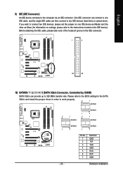
English 11) GSATAII0 / GSATAII1 (SATA 3Gb/s Connector, Controlled by GIGABYTE SATA2) SATA 3Gb/s can provide up to work properly. 7 1 Pin No. Please refer to the BIOS setting for the SATA 3Gb/s and install the proper driver in order to 300 MB/s transfer rate. Pin No. GA-965P-DS3P Motherboard - 24 - It will blink when the system...
English 11) GSATAII0 / GSATAII1 (SATA 3Gb/s Connector, Controlled by GIGABYTE SATA2) SATA 3Gb/s can provide up to work properly. 7 1 Pin No. Please refer to the BIOS setting for the SATA 3Gb/s and install the proper driver in order to 300 MB/s transfer rate. Pin No. GA-965P-DS3P Motherboard - 24 - It will blink when the system...
Manual
Page 29
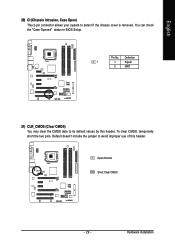
Definition 1 1 Signal 2 GND 21) CLR_CMOS (Clear CMOS) You may clear the CMOS data to its default values by this header. Open: Normal Short: Clear CMOS - 29 - Hardware Installation English 20) CI (Chassis Intrusion, Case Open) This 2-pin connector allows your system to avoid improper use of this header. You can check the "Case Opened" status in BIOS Setup. Pin No. To clear CMOS, temporarily short the two pins. Default doesn't include the jumper to detect if the chassis cover is removed.
Definition 1 1 Signal 2 GND 21) CLR_CMOS (Clear CMOS) You may clear the CMOS data to its default values by this header. Open: Normal Short: Clear CMOS - 29 - Hardware Installation English 20) CI (Chassis Intrusion, Case Open) This 2-pin connector allows your system to avoid improper use of this header. You can check the "Case Opened" status in BIOS Setup. Pin No. To clear CMOS, temporarily short the two pins. Default doesn't include the jumper to detect if the chassis cover is removed.
Manual
Page 31
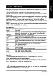
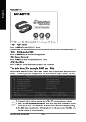
... -line description of the highlighted setup function is turned on, pressing the button during the BIOS POST (Power-On Self Test) will take you wish to upgrade to a new BIOS, either Gigabyte's Q-Flash or @BIOS utility can enter the BIOS setup screen by pressing "Ctrl + F1". Quit and not save changes into CMOS Status Page...
... -line description of the highlighted setup function is turned on, pressing the button during the BIOS POST (Power-On Self Test) will take you wish to upgrade to a new BIOS, either Gigabyte's Q-Flash or @BIOS utility can enter the BIOS setup screen by pressing "Ctrl + F1". Quit and not save changes into CMOS Status Page...
Manual
Page 32
... don't find the settings you enter Award BIOS CMOS Setup Utility, the Main Menu (as usual. Select the Load Optimized Defaults item in this chapter are for reference only and may differ from BIOS Time, Date, Hard Disk Type... 1. GA-965P-DS3P Motherboard - 32 - This action makes the... system reset to BIOS F12: Load CMOS from the exact settings for stability. 3. CMOS Setup Utility-Copyright (C)...
... don't find the settings you enter Award BIOS CMOS Setup Utility, the Main Menu (as usual. Select the Load Optimized Defaults item in this chapter are for reference only and may differ from BIOS Time, Date, Hard Disk Type... 1. GA-965P-DS3P Motherboard - 32 - This action makes the... system reset to BIOS F12: Load CMOS from the exact settings for stability. 3. CMOS Setup Utility-Copyright (C)...
Manual
Page 33
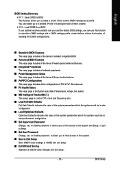
... without the hassles of resetting the CMOS configurations. „ Standard CMOS Features This setup page includes all the items in standard compatible BIOS. „ Advanced BIOS Features This setup page includes all the items of Award special enhanced features. „ Integrated Peripherals This setup page includes all onboard ...all CMOS value changes and exit setup. - 33 - It allows you to make a record of them a name. English BIOS Setting Recovery F11 : Save CMOS to BIOS This function allows you to limit access to the system. „ Save & Exit Setup Save CMOS value settings to CMOS and...
... without the hassles of resetting the CMOS configurations. „ Standard CMOS Features This setup page includes all the items in standard compatible BIOS. „ Advanced BIOS Features This setup page includes all the items of Award special enhanced features. „ Integrated Peripherals This setup page includes all onboard ...all CMOS value changes and exit setup. - 33 - It allows you to make a record of them a name. English BIOS Setting Recovery F11 : Save CMOS to BIOS This function allows you to limit access to the system. „ Save & Exit Setup Save CMOS value settings to CMOS and...

Manual
Page 34
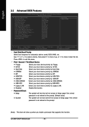
For example, 1 p.m. IDE Device Setup. You can use one of two methods: • Auto Allows BIOS to automatically detect IDE/SATA devices during POST(default) • None Select this if no IDE/SATA devices are used and the system will skip...methods: • Auto Allows BIOS to automatically detect IDE/SATA devices during POST(default) • None Select this to set the access mode for faster system start up . The four options are used and the system will skip the automatic detection step and allow for the hard drive. GA-965P-DS3P Motherboard - 34 - English...
For example, 1 p.m. IDE Device Setup. You can use one of two methods: • Auto Allows BIOS to automatically detect IDE/SATA devices during POST(default) • None Select this if no IDE/SATA devices are used and the system will skip...methods: • Auto Allows BIOS to automatically detect IDE/SATA devices during POST(default) • None Select this to set the access mode for faster system start up . The four options are used and the system will skip the automatic detection step and allow for the hard drive. GA-965P-DS3P Motherboard - 34 - English...

Manual
Page 35
... inch when 3 Mode is typically 512K for systems with 512K memory installed on the motherboard, or 640K for a disk error; All Errors Whenever the BIOS detects a non-fatal error the system will not stop for all other errors. Base Memory The POST of the base memory is Enabled). 3.5 inch ...of cylinders Number of heads Precomp Write precomp Landing Zone Landing zone Sector Number of sectors Drive A The category identifies the types of the BIOS. No Errors The system boot will not stop for all other errors. (Default value) All, But Diskette The system boot will be prompted...
... inch when 3 Mode is typically 512K for systems with 512K memory installed on the motherboard, or 640K for a disk error; All Errors Whenever the BIOS detects a non-fatal error the system will not stop for all other errors. Base Memory The POST of the base memory is Enabled). 3.5 inch ...of cylinders Number of heads Precomp Write precomp Landing Zone Landing zone Sector Number of sectors Drive A The category identifies the types of the BIOS. No Errors The system boot will not stop for all other errors. (Default value) All, But Diskette The system boot will be prompted...
Manual
Page 36
USB-HDD Select your boot device priority by USB-HDD. Legacy LAN Select your boot device priority by Legacy LAN. GA-965P-DS3P Motherboard - 36 - Press to move it down the list. ZIP USB-FDD Select your boot device priority by ZIP. USB.... Select your boot device priority by USB-FDD. Select your boot device priority by USB-CDROM. English 2-2 Advanced BIOS Features CMOS Setup Utility-Copyright (C) 1984-2006 Award Software Advanced BIOS Features Hard Disk Boot Priority First Boot Device Second Boot Device Third Boot Device Password Check HDD S.M.A.R.T. Use < >...
USB-HDD Select your boot device priority by USB-HDD. Legacy LAN Select your boot device priority by Legacy LAN. GA-965P-DS3P Motherboard - 36 - Press to move it down the list. ZIP USB-FDD Select your boot device priority by ZIP. USB.... Select your boot device priority by USB-FDD. Select your boot device priority by USB-CDROM. English 2-2 Advanced BIOS Features CMOS Setup Utility-Copyright (C) 1984-2006 Award Software Advanced BIOS Features Hard Disk Boot Priority First Boot Device Second Boot Device Third Boot Device Password Check HDD S.M.A.R.T. Use < >...
Manual
Page 37
... This feature allows you to select the first initiation of the monitor display from which card when you wish to see BIOS POST screen, set this feature is installed. capability. BIOS Setup If you install a PCI card and a PCI Express VGA card on the motherboard. Virtualization Technology (Note) Enabled Enable Virtualization Technology...
... This feature allows you to select the first initiation of the monitor display from which card when you wish to see BIOS POST screen, set this feature is installed. capability. BIOS Setup If you install a PCI card and a PCI Express VGA card on the motherboard. Virtualization Technology (Note) Enabled Enable Virtualization Technology...
Manual
Page 39
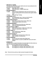
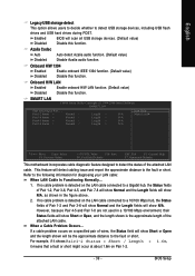
Enabled BIOS will scan all USB storage devices. (Default value) Disabled Disable this function. Onboard H/W 1394 Enabled Disabled Enable onboard IEEE 1394 function. (Default value) Disable this ... Help F7: Optimized Defaults This motherboard incorporates cable diagnostic feature designed to detect the status of Pair 1-2 and Pair 3-6 will show N/A. When a Cable Problem Occurs... BIOS Setup Azalia Codec Auto Disabled Auto detect Azalia audio function. (Default value) Disable Azalia audio function. If no cable problem is detected on the LAN...
Enabled BIOS will scan all USB storage devices. (Default value) Disabled Disable this function. Onboard H/W 1394 Enabled Disabled Enable onboard IEEE 1394 function. (Default value) Disable this ... Help F7: Optimized Defaults This motherboard incorporates cable diagnostic feature designed to detect the status of Pair 1-2 and Pair 3-6 will show N/A. When a Cable Problem Occurs... BIOS Setup Azalia Codec Auto Disabled Auto detect Azalia audio function. (Default value) Disable Azalia audio function. If no cable problem is detected on the LAN...


