Manual
Page 4
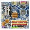
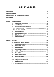
Table of Contents ItemChecklist ...6 OptionalAccessories ...6 GA-965GM-DS2 (rev. 2.0) Motherboard Layout 7 Block Diagram ...8 Chapter 1 Hardware Installation 9 1-1 Considerations Prior to Installation 9 1-2 Feature Summary 10 1-3 Installation of the CPU and CPU Cooler 12 1-3-1 Installation of the CPU 12 1-3-2 Installation of the CPU Cooler 13 1-4 Installation of Memory 14 1-5 Installation of Expansion Cards 16 1-6 I/O Back Panel Introduction 17 1-7 Connectors Introduction 18...
Table of Contents ItemChecklist ...6 OptionalAccessories ...6 GA-965GM-DS2 (rev. 2.0) Motherboard Layout 7 Block Diagram ...8 Chapter 1 Hardware Installation 9 1-1 Considerations Prior to Installation 9 1-2 Feature Summary 10 1-3 Installation of the CPU and CPU Cooler 12 1-3-1 Installation of the CPU 12 1-3-2 Installation of the CPU Cooler 13 1-4 Installation of Memory 14 1-5 Installation of Expansion Cards 16 1-6 I/O Back Panel Introduction 17 1-7 Connectors Introduction 18...
Manual
Page 8
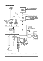
Block Diagram PCIe CLK (100 MHz) LGA775 Processor CPU CLK+/-(266/200/133 MHz) VGA PCI Express x16 2 SATA 3Gb/s LAN ATA33/66/100/133 IDE Channel GIGABYTE RJ45 Marvell SATA2 88E8056 PCI Express Bus x 1 x1 x1 PCIe CLK (100 MHz) 1 PCI Express x1 PCI Bus TSB43AB23 Host Interface DDRII 800/667/533...
Block Diagram PCIe CLK (100 MHz) LGA775 Processor CPU CLK+/-(266/200/133 MHz) VGA PCI Express x16 2 SATA 3Gb/s LAN ATA33/66/100/133 IDE Channel GIGABYTE RJ45 Marvell SATA2 88E8056 PCI Express Bus x 1 x1 x1 PCIe CLK (100 MHz) 1 PCI Express x1 PCI Bus TSB43AB23 Host Interface DDRII 800/667/533...
Manual
Page 9
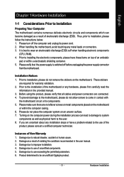
... product, please verify that the power supply is best to wear an electrostatic discharge (ESD) cuff when handling electronic components (CPU, RAM). 4. Product determined to natural disaster, accident or human cause. 2. Hardware Installation Damage due to use of uncertified ...or connectors. 3. Prior to installation, please do not allow screws to come in the provided manual. 3. Damage due to be an unofficial Gigabyte product. - 9 - Installation Notices 1. These stickers are connected. 4. Prior to the installation of the product, please consult a certified computer...
... product, please verify that the power supply is best to wear an electrostatic discharge (ESD) cuff when handling electronic components (CPU, RAM). 4. Product determined to natural disaster, accident or human cause. 2. Hardware Installation Damage due to use of uncertified ...or connectors. 3. Prior to installation, please do not allow screws to come in the provided manual. 3. Damage due to be an unofficial Gigabyte product. - 9 - Installation Notices 1. These stickers are connected. 4. Prior to the installation of the product, please consult a certified computer...
Manual
Page 10
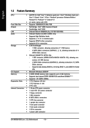
... floppy connector Š 1 IDE connector Š 6 SATA 3Gb/s connectors Š 1 CPU fan connector Š 1 system fan connector Š 1 front panel connector Š 1 front audio connector Š 1 CD In connector Š 1 power LED connector GA-965GM-DS2 (rev. 2.0) Motherboard - 10 - Supports data striping (RAID 0), mirroring (RAID 1), and ...2 SATA 3Gb/s devices - nection of 2 IDE devices - 2 SATA 3Gb/s connectors (GSATAII0,1), allowing connection of 4 SATA 3Gb/s devices Š Onboard GIGABYTE SATA2 chip - 1 IDE connector (UDMA 33/ATA 66/ATA 100/ATA 133), allowing con-
... floppy connector Š 1 IDE connector Š 6 SATA 3Gb/s connectors Š 1 CPU fan connector Š 1 system fan connector Š 1 front panel connector Š 1 front audio connector Š 1 CD In connector Š 1 power LED connector GA-965GM-DS2 (rev. 2.0) Motherboard - 10 - Supports data striping (RAID 0), mirroring (RAID 1), and ...2 SATA 3Gb/s devices - nection of 2 IDE devices - 2 SATA 3Gb/s connectors (GSATAII0,1), allowing connection of 4 SATA 3Gb/s devices Š Onboard GIGABYTE SATA2 chip - 1 IDE connector (UDMA 33/ATA 66/ATA 100/ATA 133), allowing con-

Manual
Page 11
... Speaker Out/Side Speaker Out) I/O Control Š IT8718 chip Hardware Monitor Š System voltage detection Š CPU / System temperature detection Š CPU / System fan speed detection Š CPU warning temperature Š CPU / System fan failure warning Š CPU Smart Fan Control BIOS Š 1 8 Mbit flash ROM Š Use of licensed AWARD BIOS Additional Features Š...
... Speaker Out/Side Speaker Out) I/O Control Š IT8718 chip Hardware Monitor Š System voltage detection Š CPU / System temperature detection Š CPU / System fan speed detection Š CPU warning temperature Š CPU / System fan failure warning Š CPU Smart Fan Control BIOS Š 1 8 Mbit flash ROM Š Use of licensed AWARD BIOS Additional Features Š...
Manual
Page 12
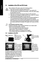
... covering and push the metal lever back into its original position. If you install the CPU in the wrong direction, the CPU will not insert properly. Fig. 2 Remove the plastic covering on the CPU socket to the CPU during installation.) GA-965GM-DS2 (rev. 2.0) Motherboard - 12 - Avoid twisting or bending motions that supports HT Technology - Please set...
... covering and push the metal lever back into its original position. If you install the CPU in the wrong direction, the CPU will not insert properly. Fig. 2 Remove the plastic covering on the CPU socket to the CPU during installation.) GA-965GM-DS2 (rev. 2.0) Motherboard - 12 - Avoid twisting or bending motions that supports HT Technology - Please set...
Manual
Page 13
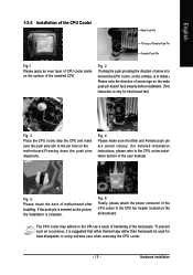
... either thermal tape rather than heat paste be used for detailed installation instructions, please refer to the CPU as the picture, the installation is inserted as a result of hardening of the CPU cooler to the CPU fan header located on the motherboard. Fig. 2 (Turning the push pin along the direction of ...arrow is to remove the CPU cooler, on the contrary, is only for Intel boxed fan) Fig. 3 Place the CPU cooler atop the CPU and make sure the Male and Female push pin are joined closely. (for heat dissipation or using...
... either thermal tape rather than heat paste be used for detailed installation instructions, please refer to the CPU as the picture, the installation is inserted as a result of hardening of the CPU cooler to the CPU fan header located on the motherboard. Fig. 2 (Turning the push pin along the direction of ...arrow is to remove the CPU cooler, on the contrary, is only for Intel boxed fan) Fig. 3 Place the CPU cooler atop the CPU and make sure the Male and Female push pin are joined closely. (for heat dissipation or using...
Manual
Page 19
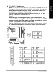
... power consumption be used (300W or greater). Before connecting the power connector, please make sure that can lead to start . It is able to the CPU. Caution! Align the power connector with its proper location on the motherboard.
... power consumption be used (300W or greater). Before connecting the power connector, please make sure that can lead to start . It is able to the CPU. Caution! Align the power connector with its proper location on the motherboard.
Manual
Page 20
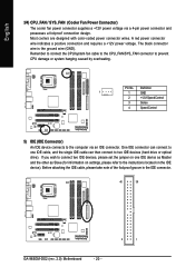
...black connector wire is the ground wire (GND). One IDE connector can then connect to prevent CPU damage or system hanging caused by overheating. Remember to connect the CPU/system fan cable to the CPU_FAN/SYS_FAN connector to two IDE devices (hard drive or optical drive...and possesses a foolproof connection design. Before attaching the IDE cable, please take note of the foolproof groove in the IDE connector. 40 39 GA-965GM-DS2 (rev. 2.0) Motherboard - 20 - 2 1 English 3/4) CPU_FAN / SYS_FAN (Cooler Fan Power Connector) The cooler fan power connector supplies a +12V power...
...black connector wire is the ground wire (GND). One IDE connector can then connect to prevent CPU damage or system hanging caused by overheating. Remember to connect the CPU/system fan cable to the CPU_FAN/SYS_FAN connector to two IDE devices (hard drive or optical drive...and possesses a foolproof connection design. Before attaching the IDE cable, please take note of the foolproof groove in the IDE connector. 40 39 GA-965GM-DS2 (rev. 2.0) Motherboard - 20 - 2 1 English 3/4) CPU_FAN / SYS_FAN (Cooler Fan Power Connector) The cooler fan power connector supplies a +12V power...

Manual
Page 31
.... „ PC Health Status This setup page is the System auto detect Temperature, voltage, fan, speed. „ Frequency/Voltage Control This setup page is control CPU clock and frequency ratio. „ Load Fail-Safe Defaults Fail-Safe Defaults indicates the value of the system parameters which the system would be in...
.... „ PC Health Status This setup page is the System auto detect Temperature, voltage, fan, speed. „ Frequency/Voltage Control This setup page is control CPU clock and frequency ratio. „ Load Fail-Safe Defaults Fail-Safe Defaults indicates the value of the system parameters which the system would be in...
Manual
Page 33
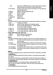
... determines whether the computer will stop if an error is determined by POST (Power On Self Test) of base (or conventional) memory installed in the CPU's memory address map. it will not stop for all other errors. The value of memory located above 1 MB in the system. No Errors The system...
... determines whether the computer will stop if an error is determined by POST (Power On Self Test) of base (or conventional) memory installed in the CPU's memory address map. it will not stop for all other errors. The value of memory located above 1 MB in the system. No Errors The system...
Manual
Page 34
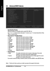
...Select your boot device priority by Floppy. LS120 Select your boot device priority by LS120. If you install a processor that supports this function. GA-965GM-DS2 (rev. 2.0) Motherboard - 34 - to make [SETUP] empty. (Note) This item will not access to move it down the list...to cancel the setting of password, please just press ENTER to 3 (Note) No-Execute Memory Protect (Note) CPU Enhanced Halt (C1E)(Note) CPU Thermal Monitor 2(TM2) (Note) CPU EIST Function (Note) Virtualization Technology(Note) Init Display First Onboard VGA On-Chip Frame Buffer Size [Press Enter]...
...Select your boot device priority by Floppy. LS120 Select your boot device priority by LS120. If you install a processor that supports this function. GA-965GM-DS2 (rev. 2.0) Motherboard - 34 - to make [SETUP] empty. (Note) This item will not access to move it down the list...to cancel the setting of password, please just press ENTER to 3 (Note) No-Execute Memory Protect (Note) CPU Enhanced Halt (C1E)(Note) CPU Thermal Monitor 2(TM2) (Note) CPU EIST Function (Note) Virtualization Technology(Note) Init Display First Onboard VGA On-Chip Frame Buffer Size [Press Enter]...
Manual
Page 35
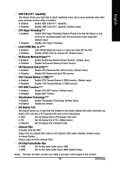
... Feature. Disabled Disable CPUID Limit for operating system with multi processors mode supported. (Default value) Disabled Disable CPU Hyper Threading. Init Display First This feature allows you to 8MB. (Default value) (Note) This item ... (Note) Enabled Enable No-Execute Memory Protect function. (Default value) Disabled Disable No-Execute Memory Protect function. capability. CPU EIST Function (Note) Enabled Enable CPU EIST function. (Default value) Disabled Disable EIST function. Virtualization Technology (Note) Enabled Enable Virtualization Technology. (Default value) ...
... Feature. Disabled Disable CPUID Limit for operating system with multi processors mode supported. (Default value) Disabled Disable CPU Hyper Threading. Init Display First This feature allows you to 8MB. (Default value) (Note) This item ... (Note) Enabled Enable No-Execute Memory Protect function. (Default value) Disabled Disable No-Execute Memory Protect function. capability. CPU EIST Function (Note) Enabled Enable CPU EIST function. (Default value) Disabled Disable EIST function. Virtualization Technology (Note) Enabled Enable Virtualization Technology. (Default value) ...

Manual
Page 41
...Status Reset Case Open Status Case Opened Vcore DDR18V +3.3V +12V Current System Temperature Current CPU Temperature Current CPU FAN Speed Current SYSTEM FAN Speed CPU Warning Temperature CPU FAN Fail Warning SYSTEM FAN Fail Warning Smart FAN Control Method Smart FAN Control Mode [...Case Open Status" to "Enabled" and save CMOS, your computer will show "Yes". Current System/CPU Temperature Detect system/CPU temperature automatically. Disable this function. (Default value) CPU/SYSTEM FAN Fail Warning Disabled Disable the fan fail warning function. (Default value) Enabled Enable the fan...
...Status Reset Case Open Status Case Opened Vcore DDR18V +3.3V +12V Current System Temperature Current CPU Temperature Current CPU FAN Speed Current SYSTEM FAN Speed CPU Warning Temperature CPU FAN Fail Warning SYSTEM FAN Fail Warning Smart FAN Control Method Smart FAN Control Mode [...Case Open Status" to "Enabled" and save CMOS, your computer will show "Yes". Current System/CPU Temperature Detect system/CPU temperature automatically. Disable this function. (Default value) CPU/SYSTEM FAN Fail Warning Disabled Disable the fan fail warning function. (Default value) Enabled Enable the fan...
Manual
Page 42
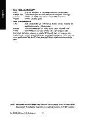
... Intel® QST (Intel® Quiet System Technology). A small portion of CPU fan you installed and sets the optimal fan speed control mode for CPU fans with a 4-pin fan power cable. With such CPU fans, selecting PWM will be used for it. (Default value) Voltage Set ...socket in Channel 0 is enabled. However, some 4-pin CPU fan power cables are not designed following Intel 4-Wire fans PWM control specifications. GA-965GM-DS2 (rev. 2.0) Motherboard - 42 - CPU fan runs at full speed. PWM Set to PWM when you use a CPU fan with 3-pin or 4-pin power cables. Note:...
... Intel® QST (Intel® Quiet System Technology). A small portion of CPU fan you installed and sets the optimal fan speed control mode for CPU fans with a 4-pin fan power cable. With such CPU fans, selecting PWM will be used for it. (Default value) Voltage Set ...socket in Channel 0 is enabled. However, some 4-pin CPU fan power cables are not designed following Intel 4-Wire fans PWM control specifications. GA-965GM-DS2 (rev. 2.0) Motherboard - 42 - CPU fan runs at full speed. PWM Set to PWM when you use a CPU fan with 3-pin or 4-pin power cables. Note:...

Manual
Page 43
...these features may cause system unable to boot. English 2-7 Frequency/Voltage Control CMOS Setup Utility-Copyright (C) 1984-2006 Award Software Frequency/Voltage Control CPU Clock Ratio (Note) System Memory Multiplier Memory Frequency (Mhz) [16X] [Auto] 533 Item Help Menu Level` KLJI: Move Enter: .../PD: Value F10: Save F6: Fail-Safe Defaults ESC: Exit F1: General Help F7: Optimized Defaults Incorrectly using these components. CPU Clock Ratio (Note) This setup option will automatically assign by DRAM SPD data). Wrong frequency settings may result in damages or shortened ...
...these features may cause system unable to boot. English 2-7 Frequency/Voltage Control CMOS Setup Utility-Copyright (C) 1984-2006 Award Software Frequency/Voltage Control CPU Clock Ratio (Note) System Memory Multiplier Memory Frequency (Mhz) [16X] [Auto] 533 Item Help Menu Level` KLJI: Move Enter: .../PD: Value F10: Save F6: Fail-Safe Defaults ESC: Exit F1: General Help F7: Optimized Defaults Incorrectly using these components. CPU Clock Ratio (Note) This setup option will automatically assign by DRAM SPD data). Wrong frequency settings may result in damages or shortened ...

Manual
Page 51
... button 6. Display screen Display panel of both CPU cooling fan and North-Bridge Chipset cooling fan, 4) PC health for enhancing system performance, 2) C.I.A. Appendix Function display LEDs Shows the current functions status 9. GIGABYTE Logo Log on different motherboards. - 51 -... 2. Smart-Fan Enters the Smart-Fan setting page 4. Help button Display EasyTuneTM 5 Help file 11. Featuring several powerful yet easy to GIGABYTE website 10. "Easy Mode" & "Advance Mode" Toggles between Easy and Advance Mode 7. and M.I .B./2 setting page 3. C.I.A./C.I.A.2 and ...
... button 6. Display screen Display panel of both CPU cooling fan and North-Bridge Chipset cooling fan, 4) PC health for enhancing system performance, 2) C.I.A. Appendix Function display LEDs Shows the current functions status 9. GIGABYTE Logo Log on different motherboards. - 51 -... 2. Smart-Fan Enters the Smart-Fan setting page 4. Help button Display EasyTuneTM 5 Help file 11. Featuring several powerful yet easy to GIGABYTE website 10. "Easy Mode" & "Advance Mode" Toggles between Easy and Advance Mode 7. and M.I .B./2 setting page 3. C.I.A./C.I.A.2 and ...

Manual
Page 65
... 1984-2006 Award Software Advanced BIOS Features Hard Disk Boot Priority First Boot Device Second Boot Device Third Boot Device Password Check CPU Hyper-Threading Limit CPUID Max. Appendix English Step 2: To boot from Windows installation CD-ROM disk, set First Boot Device ...under the Advanced BIOS Features menu to 3 No-Execute Memory Protect CPU Enhanced Halt (C1E) CPU Thermal Monitor 2(TM2) CPU EIST Function Virtualization Technology Init Display First Onboard VGA On-Chip Frame Buffer Size [Press Enter] [CDROM] [Hard Disk...
... 1984-2006 Award Software Advanced BIOS Features Hard Disk Boot Priority First Boot Device Second Boot Device Third Boot Device Password Check CPU Hyper-Threading Limit CPUID Max. Appendix English Step 2: To boot from Windows installation CD-ROM disk, set First Boot Device ...under the Advanced BIOS Features menu to 3 No-Execute Memory Protect CPU Enhanced Halt (C1E) CPU Thermal Monitor 2(TM2) CPU EIST Function Virtualization Technology Init Display First Onboard VGA On-Chip Frame Buffer Size [Press Enter] [CDROM] [Hard Disk...


