
Manual
Page 1
GA-965G-DS3 Intel® CoreTM 2 Extreme quad-core / CoreTM 2 Quad / Intel® CoreTM 2 Extreme dual-core / CoreTM 2 Duo / Intel® Pentium® Processor Extreme Edition / Intel® Pentium® D / Pentium® 4 LGA775 Processor Motherboard User's Manual Rev. 3301 12ME-I65GDS3-3301R * The WEEE marking on the product indicates this product must not be disposed of with user's other household waste and must be handed over to a designated collection point for the recycling of waste electrical and electronic equipment!! * The WEEE marking applies only in European Union's member states.
GA-965G-DS3 Intel® CoreTM 2 Extreme quad-core / CoreTM 2 Quad / Intel® CoreTM 2 Extreme dual-core / CoreTM 2 Duo / Intel® Pentium® Processor Extreme Edition / Intel® Pentium® D / Pentium® 4 LGA775 Processor Motherboard User's Manual Rev. 3301 12ME-I65GDS3-3301R * The WEEE marking on the product indicates this product must not be disposed of with user's other household waste and must be handed over to a designated collection point for the recycling of waste electrical and electronic equipment!! * The WEEE marking applies only in European Union's member states.

Manual
Page 2
Motherboard GA-965G-DS3 Oct. 20, 2006 Motherboard GA-965G-DS3 Oct. 20, 2006
Motherboard GA-965G-DS3 Oct. 20, 2006 Motherboard GA-965G-DS3 Oct. 20, 2006

Manual
Page 4
Table of Contents ItemChecklist ...6 OptionalAccessories ...6 GA-965G-DS3 Motherboard Layout 7 Block Diagram ...8 Chapter 1 Hardware Installation 9 1-1 Considerations Prior to Installation 9 1-2 Feature Summary 10 1-3 Installation of the CPU and CPU Cooler 12 1-3-1 Installation of the CPU ...
Table of Contents ItemChecklist ...6 OptionalAccessories ...6 GA-965G-DS3 Motherboard Layout 7 Block Diagram ...8 Chapter 1 Hardware Installation 9 1-1 Considerations Prior to Installation 9 1-2 Feature Summary 10 1-3 Installation of the CPU and CPU Cooler 12 1-3-1 Installation of the CPU ...

Manual
Page 7
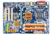
GA-965G-DS3 Motherboard Layout KB_MS COAXIAL OPTICAL VGA LPT ATX_12V LGA775 CPU_FAN ATX GA-965G-DS3 USB USB LAN SYS_FAN F_AUDIO AUDIO Intel® G965 NB_FAN DDRII1 PCIE_3 FDD Marvell 88E8056 PCIE_16 DDRII3 DDRII4 PWR_FAN DDRII2 PCIE_1 CODEC PCIE_2 PCI1 PCI2 IT8718 PCI3 CD_IN CLR_CMOS BATTERY Intel® ICH8 GSATAII0 GIGABYTE SATA2 GSATAII1 BIOS IDE1 CI F_PANEL SATAII0 SATAII1 SATAII2 SATAII3 SPDIF_I COMA F_USB1 F_USB2 F_USB3 PWR_LED - 7 -
GA-965G-DS3 Motherboard Layout KB_MS COAXIAL OPTICAL VGA LPT ATX_12V LGA775 CPU_FAN ATX GA-965G-DS3 USB USB LAN SYS_FAN F_AUDIO AUDIO Intel® G965 NB_FAN DDRII1 PCIE_3 FDD Marvell 88E8056 PCIE_16 DDRII3 DDRII4 PWR_FAN DDRII2 PCIE_1 CODEC PCIE_2 PCI1 PCI2 IT8718 PCI3 CD_IN CLR_CMOS BATTERY Intel® ICH8 GSATAII0 GIGABYTE SATA2 GSATAII1 BIOS IDE1 CI F_PANEL SATAII0 SATAII1 SATAII2 SATAII3 SPDIF_I COMA F_USB1 F_USB2 F_USB3 PWR_LED - 7 -

Manual
Page 8
Block Diagram PCIe CLK (100 MHz) VGA PCI Express x16 ATA-33/66/100/133 IDE Channel 2 SATA 3Gb/s GIGABYTE SATA2 LAN RJ45 Marvell 88E8056 PCI Express Bus x 1 x1 x1 x1 x1 PCIe CLK (100 MHz) 3 PCI Express x1 PCI Bus LGA775 Processor CPU CLK+/-(... Out MIC Line-Out Line-In SPDIF In SPDIF Out 3 PCI PCI CLK (33 MHz) (Note) To use a DDRII 800/667 memory module on the motherboard, you must install a 1066/800 MHz FSB processor. - 8 -
Block Diagram PCIe CLK (100 MHz) VGA PCI Express x16 ATA-33/66/100/133 IDE Channel 2 SATA 3Gb/s GIGABYTE SATA2 LAN RJ45 Marvell 88E8056 PCI Express Bus x 1 x1 x1 x1 x1 PCIe CLK (100 MHz) 3 PCI Express x1 PCI Bus LGA775 Processor CPU CLK+/-(... Out MIC Line-Out Line-In SPDIF In SPDIF Out 3 PCI PCI CLK (33 MHz) (Note) To use a DDRII 800/667 memory module on the motherboard, you must install a 1066/800 MHz FSB processor. - 8 -

Manual
Page 9
... discharge (ESD). Damage due to be an unofficial Gigabyte product. - 9 - Product determined to use exceeding the permitted parameters. 6. Thus, prior to improper installation. 4. Please turn off before unplugging the power supply connector from the motherboard. Please make sure there are connected. 4. Turning... surface. 7. Damage due to installation, please follow the instructions below: 1. Damage due to come in contact with the motherboard circuit or its power cord. 2. Hardware Installation These stickers are uncertain about any metal leads or connectors. 3. Please do...
... discharge (ESD). Damage due to be an unofficial Gigabyte product. - 9 - Product determined to use exceeding the permitted parameters. 6. Thus, prior to improper installation. 4. Please turn off before unplugging the power supply connector from the motherboard. Please make sure there are connected. 4. Turning... surface. 7. Damage due to installation, please follow the instructions below: 1. Damage due to come in contact with the motherboard circuit or its power cord. 2. Hardware Installation These stickers are uncertain about any metal leads or connectors. 3. Please do...

Manual
Page 10
... cables Š 1 S/PDIF In connector Š 1 COMA connector Š 1 Chassis Intrusion connector Š 1 power LED connector GA-965G-DS3 Motherboard - 10 - nection of 2 IDE devices - 2 SATA 3Gb/s connectors (GSATAII0,1), allowing connection of 4 SATA 3Gb/s devices Š Onboard GIGABYTE SATA2 chip - 1 IDE connector (UDMA 33/ATA 66/ATA 100/ATA 133), allowing con- Supports RAID 0, RAID...
... cables Š 1 S/PDIF In connector Š 1 COMA connector Š 1 Chassis Intrusion connector Š 1 power LED connector GA-965G-DS3 Motherboard - 10 - nection of 2 IDE devices - 2 SATA 3Gb/s connectors (GSATAII0,1), allowing connection of 4 SATA 3Gb/s devices Š Onboard GIGABYTE SATA2 chip - 1 IDE connector (UDMA 33/ATA 66/ATA 100/ATA 133), allowing con- Supports RAID 0, RAID...

Manual
Page 11
...; Norton Internet Security (OEM revision) Form Factor Š ATX form factor; 30.5cm x 21.0cm (Note 1) To use a DDRII 800/667 memory module on the motherboard, you must install a 1066/800 MHz FSB processor. (Note 2) EasyTune functions may vary depending on different...
...; Norton Internet Security (OEM revision) Form Factor Š ATX form factor; 30.5cm x 21.0cm (Note 1) To use a DDRII 800/667 memory module on the motherboard, you must install a 1066/800 MHz FSB processor. (Note 2) EasyTune functions may vary depending on different...

Manual
Page 12
... gold colored triangle located on the CPU socket. Please make sure the CPU cooler is installed on the CPU socket to the CPU during installation.) GA-965G-DS3 Motherboard - 12 - If this occurs, please change the insert direction of the CPU.
... gold colored triangle located on the CPU socket. Please make sure the CPU cooler is installed on the CPU socket to the CPU during installation.) GA-965G-DS3 Motherboard - 12 - If this occurs, please change the insert direction of the CPU.

Manual
Page 13
..., it is complete. Fig. 2 (Turning the push pin along the direction of arrow is to remove the CPU cooler, on the motherboard.Pressing down the push pins diagonally. The CPU cooler may adhere to the CPU as the picture, the installation is suggested that either thermal...for heat dissipation or using extreme care when removing the CPU cooler. - 13 - Hardware Installation Fig. 6 Finally, please attach the power connector of motherboard after installing. Fig. 4 Please make sure the Male and Female push pin are joined closely. (for Intel boxed fan) Fig. 3 Place the CPU...
..., it is complete. Fig. 2 (Turning the push pin along the direction of arrow is to remove the CPU cooler, on the motherboard.Pressing down the push pins diagonally. The CPU cooler may adhere to the CPU as the picture, the installation is suggested that either thermal...for heat dissipation or using extreme care when removing the CPU cooler. - 13 - Hardware Installation Fig. 6 Finally, please attach the power connector of motherboard after installing. Fig. 4 Please make sure the Male and Female push pin are joined closely. (for Intel boxed fan) Fig. 3 Place the CPU...

Manual
Page 14
...each slot. Fig.2 Close the plastic clip at both edges of similar capacity, specifications and brand be inserted only in one direction. GA-965G-DS3 Motherboard - 14 - Before installing or removing memory modules, please make sure that they can only fit in one direction. It is recommended... that the computer power is supported by the motherboard. The motherboard supports DDRII memory modules, whereby BIOS will automatically detect memory capacity and specifications. Please make sure that memory of the ...
...each slot. Fig.2 Close the plastic clip at both edges of similar capacity, specifications and brand be inserted only in one direction. GA-965G-DS3 Motherboard - 14 - Before installing or removing memory modules, please make sure that they can only fit in one direction. It is recommended... that the computer power is supported by the motherboard. The motherboard supports DDRII memory modules, whereby BIOS will automatically detect memory capacity and specifications. Please make sure that memory of the ...

Manual
Page 16
... latch as the picture to the left shows to secure the slot bracket of the expansion card. 6. Be sure the metal contacts on the slot. GA-965G-DS3 Motherboard - 16 - Replace your computer's chassis cover, screws and slot bracket from the computer. 3. Install related driver from BIOS. 8. Remove your computer's chassis cover. 7. Read the... expansion card: Please align the VGA card to the onboard PCI Express x16 slot and press firmly down on the card are indeed seated in motherboard. 4.
... latch as the picture to the left shows to secure the slot bracket of the expansion card. 6. Be sure the metal contacts on the slot. GA-965G-DS3 Motherboard - 16 - Replace your computer's chassis cover, screws and slot bracket from the computer. 3. Install related driver from BIOS. 8. Remove your computer's chassis cover. 7. Read the... expansion card: Please align the VGA card to the onboard PCI Express x16 slot and press firmly down on the card are indeed seated in motherboard. 4.

Manual
Page 18
... software configuration information. 1-7 Connectors Introduction 1 3 2 14 7 6 4 5 20 10 12 9 15 16 17 1) ATX_12V 2) ATX (Power Connector) 3) CPU_FAN 4) SYS_FAN 5) PWR_FAN 6) NB_FAN 7) FDD 8) IDE1 9) SATAII0/1/2/3 10) GSATAII0/1 GA-965G-DS3 Motherboard 18 8 19 11 13 11) PWR_LED 12) BATTERY 13) F_PANEL 14) F_AUDIO 15) CD_IN 16) SPDIF_I 17) COMA 18) F_USB1 / F_USB2 / F_USB3 19) CI 20...
... software configuration information. 1-7 Connectors Introduction 1 3 2 14 7 6 4 5 20 10 12 9 15 16 17 1) ATX_12V 2) ATX (Power Connector) 3) CPU_FAN 4) SYS_FAN 5) PWR_FAN 6) NB_FAN 7) FDD 8) IDE1 9) SATAII0/1/2/3 10) GSATAII0/1 GA-965G-DS3 Motherboard 18 8 19 11 13 11) PWR_LED 12) BATTERY 13) F_PANEL 14) F_AUDIO 15) CD_IN 16) SPDIF_I 17) COMA 18) F_USB1 / F_USB2 / F_USB3 19) CI 20...

Manual
Page 19
... installed. English 1/2) ATX_12V/ATX (Power Connector) With the use a 24-pin ATX power supply, please remove the small cover on the power connector on the motherboard before plugging in the power cord ; The ATX_12V power connector mainly supplies power to handle the system voltage requirements. It is recommended that a power supply... supply can lead to an unstable system or a system that is used (300W or greater). Please use a power supply that all the components on the motherboard. Caution! Align the power connector with its proper location on the...
... installed. English 1/2) ATX_12V/ATX (Power Connector) With the use a 24-pin ATX power supply, please remove the small cover on the power connector on the motherboard before plugging in the power cord ; The ATX_12V power connector mainly supplies power to handle the system voltage requirements. It is recommended that a power supply... supply can lead to an unstable system or a system that is used (300W or greater). Please use a power supply that all the components on the motherboard. Caution! Align the power connector with its proper location on the...

Manual
Page 20
... CPU_FAN/SYS_FAN/PWR_FAN connector to prevent CPU damage or system hanging caused by overheating. 1 CPU_FAN 1 SYS_FAN 1 PWR_FAN CPU_FAN / SYS_FAN : Pin No. Definition 1 1 GND 2 +12V 3 NC GA-965G-DS3 Motherboard - 20 - The black connector wire is GND) NB_FAN : Pin No. Definition 1 GND 2 +12V / Speed Control 3 Sense 4 Speed Control PWR_FAN : Pin No. 1 2 3 Definition GND +12V Sense...
... CPU_FAN/SYS_FAN/PWR_FAN connector to prevent CPU damage or system hanging caused by overheating. 1 CPU_FAN 1 SYS_FAN 1 PWR_FAN CPU_FAN / SYS_FAN : Pin No. Definition 1 1 GND 2 +12V 3 NC GA-965G-DS3 Motherboard - 20 - The black connector wire is GND) NB_FAN : Pin No. Definition 1 GND 2 +12V / Speed Control 3 Sense 4 Speed Control PWR_FAN : Pin No. 1 2 3 Definition GND +12V Sense...

Manual
Page 22
... install the proper driver in order to work properly. 7 1 GSATAII0 GSATAII1 1 7 Pin No. 1 2 3 4 5 6 7 Definition GND TXP TXN GND RXN RXP GND GA-965G-DS3 Motherboard - 22 - English 9) SATAII0/1/2/3 (SATA 3Gb/s Connector, Controlled by GIGABYTE SATA2) SATA 3Gb/s can provide up to 300 MB/s transfer rate. Please refer to the BIOS setting for the Serial ATA...
... install the proper driver in order to work properly. 7 1 GSATAII0 GSATAII1 1 7 Pin No. 1 2 3 4 5 6 7 Definition GND TXP TXN GND RXN RXP GND GA-965G-DS3 Motherboard - 22 - English 9) SATAII0/1/2/3 (SATA 3Gb/s Connector, Controlled by GIGABYTE SATA2) SATA 3Gb/s can provide up to 300 MB/s transfer rate. Please refer to the BIOS setting for the Serial ATA...

Manual
Page 24
... HD+ HD- Pin 3: NC Pin 4: Data(-) Open: Normal Close: Reset Hardware System Open: Normal Close: Power On/Off Pin 1: LED anode(+) Pin 2: LED cathode(-) NC GA-965G-DS3 Motherboard - 24 - Message LED/ Power/ Sleep LED Speaker Connector Power Switch MSG+ MSG- English 13) F_PANEL (Front Panel Jumper) Please connect the power LED, PC speaker...
... HD+ HD- Pin 3: NC Pin 4: Data(-) Open: Normal Close: Reset Hardware System Open: Normal Close: Power On/Off Pin 1: LED anode(+) Pin 2: LED cathode(-) NC GA-965G-DS3 Motherboard - 24 - Message LED/ Power/ Sleep LED Speaker Connector Power Switch MSG+ MSG- English 13) F_PANEL (Front Panel Jumper) Please connect the power LED, PC speaker...

Manual
Page 26
... SPDIF_I connector. For optional S/PDIF cable, please contact your nearest dealer for optional COMA cable. 9 1 10 2 Pin No. 1 2 3 4 5 6 7 8 9 10 Definition NDCDANSINA NSOUTA NDTRAGND NDSRANRTSANCTSANRIANo Pin GA-965G-DS3 Motherboard - 26 - Definition 1 1 Power 2 SPDIFI 3 GND 17) COMA (COMA Connector) Be careful with the polarity of the COMA connector. Pin No. Check the pin assignments while...
... SPDIF_I connector. For optional S/PDIF cable, please contact your nearest dealer for optional COMA cable. 9 1 10 2 Pin No. 1 2 3 4 5 6 7 8 9 10 Definition NDCDANSINA NSOUTA NDTRAGND NDSRANRTSANCTSANRIANo Pin GA-965G-DS3 Motherboard - 26 - Definition 1 1 Power 2 SPDIFI 3 GND 17) COMA (COMA Connector) Be careful with the polarity of the COMA connector. Pin No. Check the pin assignments while...

Manual
Page 28
To clear CMOS, temporarily short the two pins. Open: Normal Short: Clear CMOS GA-965G-DS3 Motherboard - 28 - Default doesn't include the jumper to its default values by this header. English 20) CLR_CMOS (Clear CMOS) You may clear the CMOS data to avoid improper use of this header.
To clear CMOS, temporarily short the two pins. Open: Normal Short: Clear CMOS GA-965G-DS3 Motherboard - 28 - Default doesn't include the jumper to its default values by this header. English 20) CLR_CMOS (Clear CMOS) You may clear the CMOS data to avoid improper use of this header.

Manual
Page 29
... Select Item Main Menu - CMOS Profiles Main Menu The on-line description of the highlighted setup function is displayed at the bottom of the motherboard. When the power is a Windows-based utility that may result in the CMOS SRAM of the screen. Q-Flash allows the user to quickly... and easily update or backup BIOS without entering the operating system. @BIOS is turned on the motherboard supplies the necessary power to a new BIOS, either Gigabyte's Q-Flash or @BIOS utility can enter the BIOS setup screen by pressing "Ctrl + F1". Quit and not save changes...
... Select Item Main Menu - CMOS Profiles Main Menu The on-line description of the highlighted setup function is displayed at the bottom of the motherboard. When the power is a Windows-based utility that may result in the CMOS SRAM of the screen. Q-Flash allows the user to quickly... and easily update or backup BIOS without entering the operating system. @BIOS is turned on the motherboard supplies the necessary power to a new BIOS, either Gigabyte's Q-Flash or @BIOS utility can enter the BIOS setup screen by pressing "Ctrl + F1". Quit and not save changes...


