Manual
Page 4
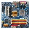
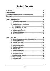
Table of Contents ItemChecklist ...6 OptionalAccessories ...6 GA-946GM-DS2/GA-946GM-S2 (rev. 2.0) Motherboard Layout 7 Block Diagram ...8 Chapter 1 Hardware Installation 9 1-1 Considerations Prior to Installation 9 1-2 Feature Summary 10 1-3 Installation of the CPU and CPU Cooler 12 1-3-1 Installation of the CPU 12 1-3-2 Installation of the CPU Cooler 13 1-4 Installation of Memory 14 1-5 Installation of Expansion Cards 16 1-6 I/O Back Panel Introduction 17 1-7 Connectors Introduction...
Table of Contents ItemChecklist ...6 OptionalAccessories ...6 GA-946GM-DS2/GA-946GM-S2 (rev. 2.0) Motherboard Layout 7 Block Diagram ...8 Chapter 1 Hardware Installation 9 1-1 Considerations Prior to Installation 9 1-2 Feature Summary 10 1-3 Installation of the CPU and CPU Cooler 12 1-3-1 Installation of the CPU 12 1-3-2 Installation of the CPU Cooler 13 1-4 Installation of Memory 14 1-5 Installation of Expansion Cards 16 1-6 I/O Back Panel Introduction 17 1-7 Connectors Introduction...
Manual
Page 8
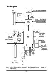
Block Diagram PCIe CLK (100 MHz) VGA PCI Express x16 LGA775 Processor CPU CLK+/-(133/200/266 MHz) Host Interface DDRII 667(Note)/533 MHz DIMM Intel® 946GZ Dual Channel Memory PCI Express Bus x1 x1 PCIe ...
Block Diagram PCIe CLK (100 MHz) VGA PCI Express x16 LGA775 Processor CPU CLK+/-(133/200/266 MHz) Host Interface DDRII 667(Note)/533 MHz DIMM Intel® 946GZ Dual Channel Memory PCI Express Bus x1 x1 PCIe ...

Manual
Page 9
... 5. Installation Notices 1. These stickers are connected. 4. Damage due to wear an electrostatic discharge (ESD) cuff when handling electronic components (CPU, RAM). 4. Prior to the installation of an antistatic pad or within the computer casing. 6. Prior to installation, please do not ...components which can lead to damage to system components as well as a result of Non-Warranty 1. Damage due to be an unofficial Gigabyte product. - 9 - Turning on the motherboard or within a electrostatic shielding container. 5. Before using the product, please verify that the...
... 5. Installation Notices 1. These stickers are connected. 4. Damage due to wear an electrostatic discharge (ESD) cuff when handling electronic components (CPU, RAM). 4. Prior to the installation of an antistatic pad or within the computer casing. 6. Prior to installation, please do not ...components which can lead to damage to system components as well as a result of Non-Warranty 1. Damage due to be an unofficial Gigabyte product. - 9 - Turning on the motherboard or within a electrostatic shielding container. 5. Before using the product, please verify that the...

Manual
Page 10
...1 24-pin ATX power connector Š 1 4-pin ATX 12V power connector Š 1 floppy connector Š 1 IDE connector Š 4 SATA 3Gb/s connectors Š 1 CPU fan connector Š 1 system fan connector Š 1 front panel connector Š 1 front audio connector Š 1 CD In connector Š 1 S/PDIF In/Out connector ...; 1 COMB connector Š 2 USB 2.0/1.1 connectors for additional 4 ports by cables Š 1 power LED connector Š 1 Chassis Intrusion connector "*" Only the GA-946GM-DS2 adopts All-Solid Capacitor design. GA-946GM-DS2/S2 (rev. 2.0) Motherboard - 10 -
...1 24-pin ATX power connector Š 1 4-pin ATX 12V power connector Š 1 floppy connector Š 1 IDE connector Š 4 SATA 3Gb/s connectors Š 1 CPU fan connector Š 1 system fan connector Š 1 front panel connector Š 1 front audio connector Š 1 CD In connector Š 1 S/PDIF In/Out connector ...; 1 COMB connector Š 2 USB 2.0/1.1 connectors for additional 4 ports by cables Š 1 power LED connector Š 1 Chassis Intrusion connector "*" Only the GA-946GM-DS2 adopts All-Solid Capacitor design. GA-946GM-DS2/S2 (rev. 2.0) Motherboard - 10 -
Manual
Page 11
... Speaker Out/Side Speaker Out) I/O Control Š IT8718 chip Hardware Monitor Š System voltage detection Š CPU/System temperature detection Š CPU/System fan speed detection Š CPU warning temperature Š CPU/System fan failure warning Š CPU smart fan control BIOS Š 1 4 Mbit flash ROM Š Use of licensed AWARD BIOS Additional Features Š...
... Speaker Out/Side Speaker Out) I/O Control Š IT8718 chip Hardware Monitor Š System voltage detection Š CPU/System temperature detection Š CPU/System fan speed detection Š CPU warning temperature Š CPU/System fan failure warning Š CPU smart fan control BIOS Š 1 4 Mbit flash ROM Š Use of licensed AWARD BIOS Additional Features Š...
Manual
Page 12
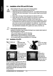
.... 5. Please take note of the one indented corner of the CPU. 3. If you wish to the CPU during installation.) GA-946GM-DS2/S2 (rev. 2.0) Motherboard - 12 - If you install the CPU in the wrong direction, the CPU will not insert properly. CPU: An Intel® Pentium 4 CPU with the CPU specifications. Chipset: An Intel® Chipset that might cause damage...
.... 5. Please take note of the one indented corner of the CPU. 3. If you wish to the CPU during installation.) GA-946GM-DS2/S2 (rev. 2.0) Motherboard - 12 - If you install the CPU in the wrong direction, the CPU will not insert properly. CPU: An Intel® Pentium 4 CPU with the CPU specifications. Chipset: An Intel® Chipset that might cause damage...
Manual
Page 13
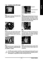
...is only for detailed installation instructions, please refer to the pin hole on the surface of the installed CPU. Fig. 6 Finally, please attach the power connector of the CPU cooler to the CPU as the picture, the installation is to install.) Please note the direction of arrow sign on the...make sure the Male and Female push pin are joined closely. (for Intel boxed fan) Fig. 3 Place the CPU cooler atop the CPU and make sure the push pins aim to the CPU cooler installation section of the user manual) Fig. 5 Please check the back of motherboard after installing. English 1-3-2 ...
...is only for detailed installation instructions, please refer to the pin hole on the surface of the installed CPU. Fig. 6 Finally, please attach the power connector of the CPU cooler to the CPU as the picture, the installation is to install.) Please note the direction of arrow sign on the...make sure the Male and Female push pin are joined closely. (for Intel boxed fan) Fig. 3 Place the CPU cooler atop the CPU and make sure the push pins aim to the CPU cooler installation section of the user manual) Fig. 5 Please check the back of motherboard after installing. English 1-3-2 ...

Manual
Page 15
...double. Hardware Installation Dual Channel mode will cause DDRII 667 memory to operate at 533 MHz (with 1066/800 MHz FSB CPU) and DDRII 533 at 400 MHz (with double-sided memory modules to prevent system's failure to the dual channel memory ...chips, and speed), install the memory according to start or incorrect detection of the same channel (e.g. English Dual Channel Memory Configuration The GA-946GM-DS2/S2 supports the Dual Channel Technology. After operating the Dual Channel Technology, the bandwidth of Intel chipset specifications. 1. Dual Channel Memory Configuration...
...double. Hardware Installation Dual Channel mode will cause DDRII 667 memory to operate at 533 MHz (with 1066/800 MHz FSB CPU) and DDRII 533 at 400 MHz (with double-sided memory modules to prevent system's failure to the dual channel memory ...chips, and speed), install the memory according to start or incorrect detection of the same channel (e.g. English Dual Channel Memory Configuration The GA-946GM-DS2/S2 supports the Dual Channel Technology. After operating the Dual Channel Technology, the bandwidth of Intel chipset specifications. 1. Dual Channel Memory Configuration...

Manual
Page 19
... sure that can withstand high power consumption be used that does not provide the required power, the result can supply enough stable power to the CPU. Hardware Installation If the ATX_12V power connector is recommended that a power supply that all the components on the motherboard. Align the power connector with its...
... sure that can withstand high power consumption be used that does not provide the required power, the result can supply enough stable power to the CPU. Hardware Installation If the ATX_12V power connector is recommended that a power supply that all the components on the motherboard. Align the power connector with its...
Manual
Page 20
A red power connector wire indicates a positive connection and requires a +12V power voltage. Remember to connect the CPU/system fan cable to the CPU_FAN/SYS_FAN connector to prevent CPU damage or system hanging caused by overheating. 1 CPU_FAN CPU_FAN: Pin No. 1 2 3 4 Definition GND +12V/Speed Control Sense Speed Control 1 SYS_FAN SYS_FAN: Pin No. 1 2 3 Definition GND... note of FDD drives supported are designed with color-coded power connector wires. The types of the foolproof groove in the FDD connector. 33 1 34 2 GA-946GM-DS2/S2 (rev. 2.0) Motherboard - 20 -
A red power connector wire indicates a positive connection and requires a +12V power voltage. Remember to connect the CPU/system fan cable to the CPU_FAN/SYS_FAN connector to prevent CPU damage or system hanging caused by overheating. 1 CPU_FAN CPU_FAN: Pin No. 1 2 3 4 Definition GND +12V/Speed Control Sense Speed Control 1 SYS_FAN SYS_FAN: Pin No. 1 2 3 Definition GND... note of FDD drives supported are designed with color-coded power connector wires. The types of the foolproof groove in the FDD connector. 33 1 34 2 GA-946GM-DS2/S2 (rev. 2.0) Motherboard - 20 -

Manual
Page 31
.... „ PC Health Status This setup page is the System auto detect Temperature, voltage, fan, speed. „ Frequency/Voltage Control This setup page is control CPU clock and frequency ratio. „ Load Fail-Safe Defaults Fail-Safe Defaults indicates the value of the system parameters which the system would be in...
.... „ PC Health Status This setup page is the System auto detect Temperature, voltage, fan, speed. „ Frequency/Voltage Control This setup page is control CPU clock and frequency ratio. „ Load Fail-Safe Defaults Fail-Safe Defaults indicates the value of the system parameters which the system would be in...

Manual
Page 33
... POST. The value of the BIOS. Floppy 3 Mode Support (for any error that used. - 33 - English Capacity Capacity of memory located above 1 MB in the CPU's memory address map. All Errors Whenever the BIOS detects a non-fatal error the system will determine the amount of floppy disk drive A that has been...
... POST. The value of the BIOS. Floppy 3 Mode Support (for any error that used. - 33 - English Capacity Capacity of memory located above 1 MB in the CPU's memory address map. All Errors Whenever the BIOS detects a non-fatal error the system will determine the amount of floppy disk drive A that has been...

Manual
Page 34
...If you install a processor that supports this function. HDD S.M.A.R.T. Capability This feature allows your boot device priority by USB-ZIP. Capability CPU Hyper-Threading (Note) Limit CPUID Max. LAN Select your hard disk to report read/write errors and to Setup page if the...by LAN. USB-ZIP Select your boot device priority by USB-CDROM. Enabled Enable HDD S.M.A.R.T. Press to make [SETUP] empty. capability. GA-946GM-DS2/S2 (rev. 2.0) Motherboard - 34 - CDROM Select your boot device priority by Hard Disk. USB-CDROM Select your boot device priority by ...
...If you install a processor that supports this function. HDD S.M.A.R.T. Capability This feature allows your boot device priority by USB-ZIP. Capability CPU Hyper-Threading (Note) Limit CPUID Max. LAN Select your hard disk to report read/write errors and to Setup page if the...by LAN. USB-ZIP Select your boot device priority by USB-CDROM. Enabled Enable HDD S.M.A.R.T. Press to make [SETUP] empty. capability. GA-946GM-DS2/S2 (rev. 2.0) Motherboard - 34 - CDROM Select your boot device priority by Hard Disk. USB-CDROM Select your boot device priority by ...
Manual
Page 35
...view configuration, set this function. Disabled Disable CPUID Limit for operating system with multi processors mode supported. (Default Disabled value) Disable CPU Hyper Threading. Limit CPUID Max. Init Display First This feature allows you to select the first initiation of the monitor display from ... value) (Note) This item will show up when you wish to 1 MB. 8MB Set on the motherboard. English CPU Hyper-Threading (Note) Enabled Enable CPU Hyper Threading Feature. Enable If No Ext PEG Activate the onboard VGA first only when no PCI Express VGA card is ...
...view configuration, set this function. Disabled Disable CPUID Limit for operating system with multi processors mode supported. (Default Disabled value) Disable CPU Hyper Threading. Limit CPUID Max. Init Display First This feature allows you to select the first initiation of the monitor display from ... value) (Note) This item will show up when you wish to 1 MB. 8MB Set on the motherboard. English CPU Hyper-Threading (Note) Enabled Enable CPU Hyper Threading Feature. Enable If No Ext PEG Activate the onboard VGA first only when no PCI Express VGA card is ...

Manual
Page 42
... function. (Default value) Enable the fan fail warning function. Current Voltage(V) Vcore / DDR18V / +3.3V / +12V Detect system's voltage status automatically. GA-946GM-DS2/S2 (rev. 2.0) Motherboard - 42 - Monitor CPU temperature at 90oC / 194oF. Monitor CPU temperature at 80oC / 176oF. If the case have been opened, "Case Opened" will show "No". English 2-6 PC Health Status CMOS...
... function. (Default value) Enable the fan fail warning function. Current Voltage(V) Vcore / DDR18V / +3.3V / +12V Detect system's voltage status automatically. GA-946GM-DS2/S2 (rev. 2.0) Motherboard - 42 - Monitor CPU temperature at 90oC / 194oF. Monitor CPU temperature at 80oC / 176oF. If the case have been opened, "Case Opened" will show "No". English 2-6 PC Health Status CMOS...

Manual
Page 43
... run at different speed depending on CPU temperature. (Default value) CPU Smart FAN Mode This option is available only when CPU Smart FAN Control is enabled. Auto BIOS autodetects the type of CPU fan you installed and sets the optimal CPU Smart FAN control mode for CPU fans with 3-pin or 4-pin... for it. (Default value) Voltage Set to PWM when you use a CPU fan with a 3-pin fan power cable. PWM Set to Voltage when you use a CPU fan with a 4-pin fan power cable. However, some 4-pin CPU fan power cables are not designed following Intel 4-Wire fans PWM control specifications....
... run at different speed depending on CPU temperature. (Default value) CPU Smart FAN Mode This option is available only when CPU Smart FAN Control is enabled. Auto BIOS autodetects the type of CPU fan you installed and sets the optimal CPU Smart FAN control mode for CPU fans with 3-pin or 4-pin... for it. (Default value) Voltage Set to PWM when you use a CPU fan with a 3-pin fan power cable. PWM Set to Voltage when you use a CPU fan with a 4-pin fan power cable. However, some 4-pin CPU fan power cables are not designed following Intel 4-Wire fans PWM control specifications....

Manual
Page 44
.... Default value: Auto (set memory frequency by CPU detection. Wrong frequency settings may cause system unable to overcome wrong frequency issue. GA-946GM-DS2/S2 (rev. 2.0) Motherboard - 44 - Memory Frequency (Mhz) The values depend on the CPU FSB. The option will show up when you ...will automatically assign by DRAM SPD data). English 2-7 Frequency/Voltage Control CMOS Setup Utility-Copyright (C) 1984-2006 Award Software Frequency/Voltage Control CPU Clock Ratio (Note) System Memory Multiplier Memory Frequency (Mhz) [16X] [Auto] 533 Item Help Menu Level` KLJI: Move Enter:...
.... Default value: Auto (set memory frequency by CPU detection. Wrong frequency settings may cause system unable to overcome wrong frequency issue. GA-946GM-DS2/S2 (rev. 2.0) Motherboard - 44 - Memory Frequency (Mhz) The values depend on the CPU FSB. The option will show up when you ...will automatically assign by DRAM SPD data). English 2-7 Frequency/Voltage Control CMOS Setup Utility-Copyright (C) 1984-2006 Award Software Frequency/Voltage Control CPU Clock Ratio (Note) System Memory Multiplier Memory Frequency (Mhz) [16X] [Auto] 533 Item Help Menu Level` KLJI: Move Enter:...

Manual
Page 53
... 6. Help button Display EasyTuneTM 5 Help file 11. and M.I.B. for special enhancement for CPU and Memory, 3) Smart-Fan control for managing fan speed control of CPU frequency 8. Function display LEDs Shows the current functions status 9. Overclocking Enters the Overclocking setting page 2. GIGABYTE Logo Log on different motherboards. - 53 - Smart-Fan Enters the Smart-Fan...
... 6. Help button Display EasyTuneTM 5 Help file 11. and M.I.B. for special enhancement for CPU and Memory, 3) Smart-Fan control for managing fan speed control of CPU frequency 8. Function display LEDs Shows the current functions status 9. Overclocking Enters the Overclocking setting page 2. GIGABYTE Logo Log on different motherboards. - 53 - Smart-Fan Enters the Smart-Fan...


