
Manual
Page 4
Table of Contents ItemChecklist ...6 OptionalAccessories ...6 GA-945GZM-S2 Motherboard Layout 7 Block Diagram ...8 Chapter 1 Hardware Installation 9 1-1 Considerations Prior to Installation 9 1-2 Feature Summary 10 1-3 Installation of the CPU and CPU Cooler...BIOS Setup 29 The Main Menu (For example: BIOS Ver. : FHa 30 2-1 Standard CMOS Features 32 2-2 Advanced BIOS Features 34 2-3 IntegratedPeripherals 36 2-4 Power Management Setup 40 2-5 PnP/PCI Configurations 42 2-6 PC Health Status 43 2-7 Frequency/Voltage Control 45 2-8 Load Fail-Safe Defaults 47 2-9 Load Optimized Defaults 47...
Table of Contents ItemChecklist ...6 OptionalAccessories ...6 GA-945GZM-S2 Motherboard Layout 7 Block Diagram ...8 Chapter 1 Hardware Installation 9 1-1 Considerations Prior to Installation 9 1-2 Feature Summary 10 1-3 Installation of the CPU and CPU Cooler...BIOS Setup 29 The Main Menu (For example: BIOS Ver. : FHa 30 2-1 Standard CMOS Features 32 2-2 Advanced BIOS Features 34 2-3 IntegratedPeripherals 36 2-4 Power Management Setup 40 2-5 PnP/PCI Configurations 42 2-6 PC Health Status 43 2-7 Frequency/Voltage Control 45 2-8 Load Fail-Safe Defaults 47 2-9 Load Optimized Defaults 47...
Manual
Page 9
...Gigabyte product. - 9 - Prior to installation, please do not remove the stickers on an uneven surface. 7. Damage due to use of an antistatic pad or within the computer casing. 6. When handling the motherboard, avoid touching any installation steps or have these items on the computer power...to the installation of the motherboard or any hardware, please first carefully read the information in contact with the motherboard circuit or its power cord. 2. To prevent damage to the motherboard, please do not place the computer system on the motherboard. Instances of uncertified ...
...Gigabyte product. - 9 - Prior to installation, please do not remove the stickers on an uneven surface. 7. Damage due to use of an antistatic pad or within the computer casing. 6. When handling the motherboard, avoid touching any installation steps or have these items on the computer power...to the installation of the motherboard or any hardware, please first carefully read the information in contact with the motherboard circuit or its power cord. 2. To prevent damage to the motherboard, please do not place the computer system on the motherboard. Instances of uncertified ...
Manual
Page 10
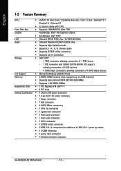
...; Supports 1.8V DDRII DIMMs Expanstion Slots Š 1 PCI Express x16 slot(Note 1) Š 3 PCI slots Internal Connectors Š 1 24-pin ATX power connector Š 1 4-pin ATX 12V power connector Š 1 floppy connector Š 1 IDE connector Š 4 SATA 3Gb/s connectors Š 1 CPU fan connector Š 1 system fan connector...1 CD In connector Š 1 S/PDIF In/Out connector Š 2 USB 2.0/1.1 connectors for additional 4 USB 2.0/1.1 ports by cables Š 1 COMB connector Š 1 power LED connector Š 1 Chassis Intrusion connector GA-945GZM-S2 Motherboard - 10 -
...; Supports 1.8V DDRII DIMMs Expanstion Slots Š 1 PCI Express x16 slot(Note 1) Š 3 PCI slots Internal Connectors Š 1 24-pin ATX power connector Š 1 4-pin ATX 12V power connector Š 1 floppy connector Š 1 IDE connector Š 4 SATA 3Gb/s connectors Š 1 CPU fan connector Š 1 system fan connector...1 CD In connector Š 1 S/PDIF In/Out connector Š 2 USB 2.0/1.1 connectors for additional 4 USB 2.0/1.1 ports by cables Š 1 COMB connector Š 1 power LED connector Š 1 Chassis Intrusion connector GA-945GZM-S2 Motherboard - 10 -
Manual
Page 13
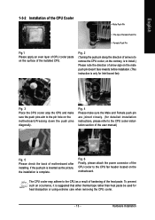
Fig. 6 Finally, please attach the power connector of the CPU cooler to the CPU cooler installation section of the user manual) Fig. 5 Please check the back of motherboard after installing. Hardware ...
Fig. 6 Finally, please attach the power connector of the CPU cooler to the CPU cooler installation section of the user manual) Fig. 5 Please check the back of motherboard after installing. Hardware ...
Manual
Page 14
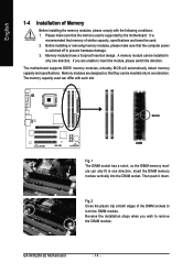
... module can differ with the following conditions: 1. Then push it down. Reverse the installation steps when you are designed so that the computer power is supported by the motherboard. GA-945GZM-S2 Motherboard - 14 - The memory capacity used . 2. If you wish to prevent hardware damage. 3. Before installing or removing memory modules, please make sure...
... module can differ with the following conditions: 1. Then push it down. Reverse the installation steps when you are designed so that the computer power is supported by the motherboard. GA-945GZM-S2 Motherboard - 14 - The memory capacity used . 2. If you wish to prevent hardware damage. 3. Before installing or removing memory modules, please make sure...

Manual
Page 15
... expansion card into the PCI Express x16 slot. Press the expansion card firmly into DIMM sockets of the same color. 1-5 Installation of the expansion card. 6. Power on the top edge of expansion card from the computer. 3. For example: Installing a PCI Express x16 VGA card: When installing the graphics card, push down... limitation of Memory Bus will not be enabled if only one memory module is fully inserted into the computer. 2. English Dual Channel Memory Configuration The GA-945GZM-S2 supports the Dual Channel Technology.
... expansion card into the PCI Express x16 slot. Press the expansion card firmly into DIMM sockets of the same color. 1-5 Installation of the expansion card. 6. Power on the top edge of expansion card from the computer. 3. For example: Installing a PCI Express x16 VGA card: When installing the graphics card, push down... limitation of Memory Bus will not be enabled if only one memory module is fully inserted into the computer. 2. English Dual Channel Memory Configuration The GA-945GZM-S2 supports the Dual Channel Technology.
Manual
Page 18
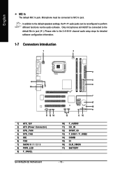
... configuration information. 1-7 Connectors Introduction 1 3 4 10 11 12 14 1) ATX_12V 2) ATX (Power Connector) 3) CPU_FAN 4) SYS_FAN 5) IDE 6) FDD 7) SATAII 0 / 1 / 2 / 3 8) PWR_LED 9) F_PANEL 2 5 6 7 17 15 9 13 8 16 10) F_AUDIO 11) CD_IN 12) SPDIF_IO 13) F_USB1 / F_USB2 14) COMB 15) CI 16) CLR_CMOS 17) BATTERY GA-945GZM-S2 Motherboard - 18 - Only microphones still MUST be connected to the default...
... configuration information. 1-7 Connectors Introduction 1 3 4 10 11 12 14 1) ATX_12V 2) ATX (Power Connector) 3) CPU_FAN 4) SYS_FAN 5) IDE 6) FDD 7) SATAII 0 / 1 / 2 / 3 8) PWR_LED 9) F_PANEL 2 5 6 7 17 15 9 13 8 16 10) F_AUDIO 11) CD_IN 12) SPDIF_IO 13) F_USB1 / F_USB2 14) COMB 15) CI 16) CLR_CMOS 17) BATTERY GA-945GZM-S2 Motherboard - 18 - Only microphones still MUST be connected to the default...

Manual
Page 19
...please make sure that can withstand high power consumption be used that does not provide the required power, the result can supply enough stable power to all components and devices are properly installed. The ATX_12V power connector mainly supplies power to the CPU. It is recommended that a power supply that all the components on the ... Pin No. 1 2 3 4 Definition GND GND +12V +12V 12 24 1 13 ATX Pin No. 1 2 3 4 5 6 7 8 9 10 11 12 Definition 3.3V 3.3V GND +5V GND +5V GND Power Good 5V SB(stand by +5V) +12V +12V(Only for 24-pin ATX) 3.3V(Only for 24-pin ATX) Pin No. 13 14 15 16...
...please make sure that can withstand high power consumption be used that does not provide the required power, the result can supply enough stable power to all components and devices are properly installed. The ATX_12V power connector mainly supplies power to the CPU. It is recommended that a power supply that all the components on the ... Pin No. 1 2 3 4 Definition GND GND +12V +12V 12 24 1 13 ATX Pin No. 1 2 3 4 5 6 7 8 9 10 11 12 Definition 3.3V 3.3V GND +5V GND +5V GND Power Good 5V SB(stand by +5V) +12V +12V(Only for 24-pin ATX) 3.3V(Only for 24-pin ATX) Pin No. 13 14 15 16...

Manual
Page 20
.... Before attaching the IDE cable, please take note of the foolproof groove in the IDE connector. 40 39 GA-945GZM-S2 Motherboard - 20 - 2 1 Most coolers are designed with color-coded power connector wires. The black connector wire is the ground wire (GND). Remember to connect the CPU/system fan...). If you wish to two IDE devices (hard drive or optical drive). English 3/4) CPU_FAN / SYS_FAN (Cooler Fan Power Connector) The cooler fan power connector supplies a +12V power voltage via an IDE connector. One IDE connector can connect to one IDE cable, and the single IDE cable can ...
.... Before attaching the IDE cable, please take note of the foolproof groove in the IDE connector. 40 39 GA-945GZM-S2 Motherboard - 20 - 2 1 Most coolers are designed with color-coded power connector wires. The black connector wire is the ground wire (GND). Remember to connect the CPU/system fan...). If you wish to two IDE devices (hard drive or optical drive). English 3/4) CPU_FAN / SYS_FAN (Cooler Fan Power Connector) The cooler fan power connector supplies a +12V power voltage via an IDE connector. One IDE connector can connect to one IDE cable, and the single IDE cable can ...
Manual
Page 22
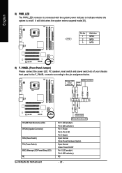
... system is connected with the system power indicator to the pin assignment below. RESRES+ NC HD (IDE Hard Disk Active LED) SPEAK (Speaker Connector) RES (Reset Switch) PW (Power Switch) MSG (Message LED/Power/Sleep LED) NC GA-945GZM-S2 Motherboard Reset Switch IDE Hard Disk ...Active LED Pin 1: LED anode(+) Pin 2: LED cathode(-) Pin 1: Power Pin 2- Message LED/ Power/ Sleep LED Speaker Connector Power Switch MSG+ MSG-
... system is connected with the system power indicator to the pin assignment below. RESRES+ NC HD (IDE Hard Disk Active LED) SPEAK (Speaker Connector) RES (Reset Switch) PW (Power Switch) MSG (Message LED/Power/Sleep LED) NC GA-945GZM-S2 Motherboard Reset Switch IDE Hard Disk ...Active LED Pin 1: LED anode(+) Pin 2: LED cathode(-) Pin 1: Power Pin 2- Message LED/ Power/ Sleep LED Speaker Connector Power Switch MSG+ MSG-
Manual
Page 23
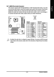
... to the instructions on Page 66 about the software settings. - 23 - If you connect the front panel audio module. Hardware Installation Definition 1 MIC 2 GND 3 MIC Power 4 NC 5 Line Out (R) 6 NC 7 NC 8 No Pin 9 Line Out (L) 10 NC By default, the audio driver is configured to work or even damage it. English...
... to the instructions on Page 66 about the software settings. - 23 - If you connect the front panel audio module. Hardware Installation Definition 1 MIC 2 GND 3 MIC Power 4 NC 5 Line Out (R) 6 NC 7 NC 8 No Pin 9 Line Out (L) 10 NC By default, the audio driver is configured to work or even damage it. English...
Manual
Page 24
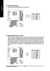
... unable to an external Dolby Digital Decoder. Pin No. Use this feature only when your local dealer. 51 62 Pin No. 1 2 3 4 5 6 Definition Power No Pin SPDIF SPDIFI GND GND GA-945GZM-S2 Motherboard - 24 - English 11) CD_IN (CD In Connector) Connect CD-ROM or DVD-ROM audio out to the connector. Use S/PDIF IN...
... unable to an external Dolby Digital Decoder. Pin No. Use this feature only when your local dealer. 51 62 Pin No. 1 2 3 4 5 6 Definition Power No Pin SPDIF SPDIFI GND GND GA-945GZM-S2 Motherboard - 24 - English 11) CD_IN (CD In Connector) Connect CD-ROM or DVD-ROM audio out to the connector. Use S/PDIF IN...

Manual
Page 25
... optional COMB cable. 9 1 10 2 Pin No. 1 2 3 4 5 6 7 8 9 10 Definition NDCDBNSINB NSOUTB NDTRBGND NDSRBNRTSBNCTSBNRIBNo Pin - 25 - Please contact your local dealer. 9 1 10 2 Pin No. 1 2 3 4 5 6 7 8 9 10 Definition Power (5V) Power (5V) USB DXUSB DyUSB DX+ USB Dy+ GND GND No Pin NC 14) COMB (COMB Connector) Be careful with the polarity of the COMB connector...
... optional COMB cable. 9 1 10 2 Pin No. 1 2 3 4 5 6 7 8 9 10 Definition NDCDBNSINB NSOUTB NDTRBGND NDSRBNRTSBNCTSBNRIBNo Pin - 25 - Please contact your local dealer. 9 1 10 2 Pin No. 1 2 3 4 5 6 7 8 9 10 Definition Power (5V) Power (5V) USB DXUSB DyUSB DX+ USB Dy+ GND GND No Pin NC 14) COMB (COMB Connector) Be careful with the polarity of the COMB connector...

Manual
Page 27
... a metal object to connect the positive and negative pins in and turn on the computer. - 27 - Turn off the computer and unplug the power cord. 2. Plug the power cord in the battery holder to makethem short for five seconds.) 3. English 17) BATTERY Danger of used batteries according to the manufacturer's instructions. Hardware...
... a metal object to connect the positive and negative pins in and turn on the computer. - 27 - Turn off the computer and unplug the power cord. 2. Plug the power cord in the battery holder to makethem short for five seconds.) 3. English 17) BATTERY Danger of used batteries according to the manufacturer's instructions. Hardware...
Manual
Page 29
... to use and the possible selections for the highlighted item. To exit the Help Window press . Exit current page and return to a new BIOS, either GIGABYTE's Q-Flash or @BIOS utility can enter the BIOS setup screen by pressing "Ctrl + F1". Status Page Setup Menu / Option Page Setup Menu Press to pop... from CMOS, only for Option Page Setup Menu Load the fail-safe default CMOS value from the Internet. When the power is turned on, press the button during the BIOS POST (Power-On Self Test) will take you wish to upgrade to Main Menu Increase the numeric value or make changes Decrease...
... to use and the possible selections for the highlighted item. To exit the Help Window press . Exit current page and return to a new BIOS, either GIGABYTE's Q-Flash or @BIOS utility can enter the BIOS setup screen by pressing "Ctrl + F1". Status Page Setup Menu / Option Page Setup Menu Press to pop... from CMOS, only for Option Page Setup Menu Load the fail-safe default CMOS value from the Internet. When the power is turned on, press the button during the BIOS POST (Power-On Self Test) will take you wish to upgrade to Main Menu Increase the numeric value or make changes Decrease...
Manual
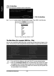
Page 30
...6A89HG00C-00 : For Boot Menu Use < > or < > to select a device, then press enter to accept or enter the sub-menu. GA-945GZM-S2 Motherboard - 30 - Award Modular BIOS v6.00PG, An Energy Star Ally Copyright (C) 1984-2007, Award Software, Inc. CMOS Setup Utility-Copyright (C)... 1984-2007 Award Software ` Standard CMOS Features ` Advanced BIOS Features ` Integrated Peripherals ` Power Management Setup ` PnP/PCI Configurations ` PC Health Status ` Frequency/Voltage Control ESC: Quit F8: Q-Flash Load Fail-Safe Defaults Load Optimized ...
...6A89HG00C-00 : For Boot Menu Use < > or < > to select a device, then press enter to accept or enter the sub-menu. GA-945GZM-S2 Motherboard - 30 - Award Modular BIOS v6.00PG, An Energy Star Ally Copyright (C) 1984-2007, Award Software, Inc. CMOS Setup Utility-Copyright (C)... 1984-2007 Award Software ` Standard CMOS Features ` Advanced BIOS Features ` Integrated Peripherals ` Power Management Setup ` PnP/PCI Configurations ` PC Health Status ` Frequency/Voltage Control ESC: Quit F8: Q-Flash Load Fail-Safe Defaults Load Optimized ...
Manual
Page 31
... BIOS Features This setup page includes all the items of Award special enhanced features. „ Integrated Peripherals This setup page includes all onboard peripherals. „ Power Management Setup This setup page includes all the items of Green function features. „ PnP/PCI Configuration This setup page includes all CMOS value changes...
... BIOS Features This setup page includes all the items of Award special enhanced features. „ Integrated Peripherals This setup page includes all onboard peripherals. „ Power Management Setup This setup page includes all the items of Green function features. „ PnP/PCI Configuration This setup page includes all CMOS value changes...
Manual
Page 33
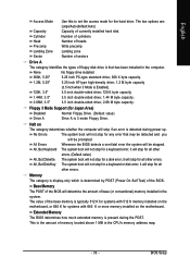
...; 360 K byte capacity. 1.2M, 5.25" 5.25 inch AT-type high-density drive; 1.2 M byte capacity (3.5 inch when 3 Mode is determined by POST (Power On Self Test) of base (or conventional) memory installed in the computer. No Errors The system boot will stop for a keyboard error; All, But Keyboard...Diskette The system boot will not stop for a disk error; Base Memory The POST of the BIOS will be prompted. This is present during power up. Whenever the BIOS detects a non-fatal error the system will determine the amount of the BIOS. it will stop for the hard ...
...; 360 K byte capacity. 1.2M, 5.25" 5.25 inch AT-type high-density drive; 1.2 M byte capacity (3.5 inch when 3 Mode is determined by POST (Power On Self Test) of base (or conventional) memory installed in the computer. No Errors The system boot will stop for a keyboard error; All, But Keyboard...Diskette The system boot will not stop for a disk error; Base Memory The POST of the BIOS will be prompted. This is present during power up. Whenever the BIOS detects a non-fatal error the system will determine the amount of the BIOS. it will stop for the hard ...
Manual
Page 40
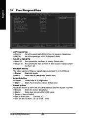
..., 1~31 Time (hh: mm: ss) Alarm : (0~23) : (0~59) : (0~59) GA-945GZM-S2 Motherboard - 40 - Enter suspend if button is Enabled. Disabled Disable this function. Press power button 4 sec. to power on the 5VSB lead. English 2-4 Power Management Setup CMOS Setup Utility-Copyright (C) 1984-2007 Award Software Power Management Setup ACPI Suspend Type Soft-Off by PWR-BTTN...
..., 1~31 Time (hh: mm: ss) Alarm : (0~23) : (0~59) : (0~59) GA-945GZM-S2 Motherboard - 40 - Enter suspend if button is Enabled. Disabled Disable this function. Press power button 4 sec. to power on the 5VSB lead. English 2-4 Power Management Setup CMOS Setup Utility-Copyright (C) 1984-2007 Award Software Power Management Setup ACPI Suspend Type Soft-Off by PWR-BTTN...

Manual
Page 41
...(Default value) Double Click Double click on PS/2 mouse left button to the Last state before AC-power off. - 41 - Enter Input password(from 1 to 5 characters to set the password. When AC-power back to the system, the system will be in "Off" state. (Default value) Full-On ...Memory When AC-power back to power on the system. KB Power ON Password When "Power On by Keyboard" set at Password, you can set the password here. English Power On By Mouse Disabled Disable this function. (Default value) Password Enter from 1 to...
...(Default value) Double Click Double click on PS/2 mouse left button to the Last state before AC-power off. - 41 - Enter Input password(from 1 to 5 characters to set the password. When AC-power back to the system, the system will be in "Off" state. (Default value) Full-On ...Memory When AC-power back to power on the system. KB Power ON Password When "Power On by Keyboard" set at Password, you can set the password here. English Power On By Mouse Disabled Disable this function. (Default value) Password Enter from 1 to...


