Manual
Page 1
GA-945GM-S2 / GA-945GM-DS2 / GA-945GMF-DS2 Intel® CoreTM 2 Extreme dual-core / CoreTM 2 Duo Intel® Pentium® D / Pentium® 4 / Celeron® D LGA775 Processor Motherboard User's Manual Rev. 3901 12ME-945GMFDR-3901R * The WEEE marking on the product indicates this product must not be disposed of with user's other household waste and must be handed over to a designated collection point for the recycling of waste electrical and electronic equipment!! * The WEEE marking applies only in European Union's member states.
GA-945GM-S2 / GA-945GM-DS2 / GA-945GMF-DS2 Intel® CoreTM 2 Extreme dual-core / CoreTM 2 Duo Intel® Pentium® D / Pentium® 4 / Celeron® D LGA775 Processor Motherboard User's Manual Rev. 3901 12ME-945GMFDR-3901R * The WEEE marking on the product indicates this product must not be disposed of with user's other household waste and must be handed over to a designated collection point for the recycling of waste electrical and electronic equipment!! * The WEEE marking applies only in European Union's member states.
Manual
Page 2
Motherboard GA-945GM-DS2/GA-945GMF-DS2 Nov. 10, 2006 Motherboard GA-945GM-DS2/ GA-945GMF-DS2 Nov. 10, 2006
Motherboard GA-945GM-DS2/GA-945GMF-DS2 Nov. 10, 2006 Motherboard GA-945GM-DS2/ GA-945GMF-DS2 Nov. 10, 2006
Manual
Page 3
Motherboard GA-945GM-S2 Jul. 7, 2006 Motherboard GA-945GM-S2 Jul. 7, 2006
Motherboard GA-945GM-S2 Jul. 7, 2006 Motherboard GA-945GM-S2 Jul. 7, 2006
Manual
Page 5
Table of Contents ItemChecklist ...7 OptionalAccessories ...7 GA-945GM-S2/GA-945GM-DS2/GA-945GMF-DS2 Motherboard Layout 8 Block Diagram ...9 Chapter 1 Hardware Installation 11 1-1 Considerations Prior to Installation 11 1-2 Feature Summary 12 1-3 Installation...1-5 Installation of Expansion Cards 18 1-6 I/O Back Panel Introduction 19 1-7 Connectors Introduction 20 Chapter 2 BIOS Setup 31 The Main Menu (For example: GA-945GMF-DS2 BIOS Ver. : F1a 32 2-1 Standard CMOS Features 34 2-2 Advanced BIOS Features 36 2-3 IntegratedPeripherals 38 2-4 Power Management Setup 42 2-5 PnP/PCI ...
Table of Contents ItemChecklist ...7 OptionalAccessories ...7 GA-945GM-S2/GA-945GM-DS2/GA-945GMF-DS2 Motherboard Layout 8 Block Diagram ...9 Chapter 1 Hardware Installation 11 1-1 Considerations Prior to Installation 11 1-2 Feature Summary 12 1-3 Installation...1-5 Installation of Expansion Cards 18 1-6 I/O Back Panel Introduction 19 1-7 Connectors Introduction 20 Chapter 2 BIOS Setup 31 The Main Menu (For example: GA-945GMF-DS2 BIOS Ver. : F1a 32 2-1 Standard CMOS Features 34 2-2 Advanced BIOS Features 36 2-3 IntegratedPeripherals 38 2-4 Power Management Setup 42 2-5 PnP/PCI ...
Manual
Page 8
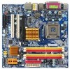
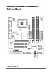
GA-945GM-S2/GA-945GM-DS2/GA-945GMF-DS2 Motherboard Layout KB_MS ATX_12V LGA775 CPU_FAN IT8718 VGA COMA LPT GA-945GM-S2/GA-945GM-DS2 /GA-945GMF-DS2 USB 1394 USB LAN F_AUDIO BATTERY CLR_CMOS AUDIO SYS_FAN PCIE_16 RTL8111B PCI1 PCI2 CD_IN PCIE_1 CODEC SPDIF_IO FDD Intel® 945G DDRII1 DDRII2 BIOS TSB43AB23 Intel® ICH7 COMB F1_1394 F2_1394 DDRII3 DDRII4 SATAII0 SATAII2 IDE ATX CI F_PANEL SATAII1 SATAII3 F_USB1 F_USB2 PWR_LED Only for GA-945GMF-DS2. - 8 -
GA-945GM-S2/GA-945GM-DS2/GA-945GMF-DS2 Motherboard Layout KB_MS ATX_12V LGA775 CPU_FAN IT8718 VGA COMA LPT GA-945GM-S2/GA-945GM-DS2 /GA-945GMF-DS2 USB 1394 USB LAN F_AUDIO BATTERY CLR_CMOS AUDIO SYS_FAN PCIE_16 RTL8111B PCI1 PCI2 CD_IN PCIE_1 CODEC SPDIF_IO FDD Intel® 945G DDRII1 DDRII2 BIOS TSB43AB23 Intel® ICH7 COMB F1_1394 F2_1394 DDRII3 DDRII4 SATAII0 SATAII2 IDE ATX CI F_PANEL SATAII1 SATAII3 F_USB1 F_USB2 PWR_LED Only for GA-945GMF-DS2. - 8 -
Manual
Page 9
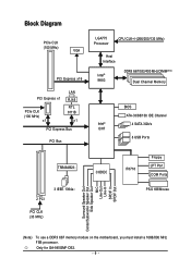
... Center/Subwoofer Speaker Out Side Speaker Out MIC Line-Out Line-In SPDIF In SPDIF Out (Note) To use a DDRII 667 memory module on the motherboard, you must install a 1066/800 MHz FSB processor. Only for GA-945GMF-DS2. - 9 -
... Center/Subwoofer Speaker Out Side Speaker Out MIC Line-Out Line-In SPDIF In SPDIF Out (Note) To use a DDRII 667 memory module on the motherboard, you must install a 1066/800 MHz FSB processor. Only for GA-945GMF-DS2. - 9 -
Manual
Page 11
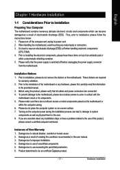
Before using the product, please verify that the power supply is best to be an unofficial Gigabyte product. - 11 - Please make sure there are connected. 4. Please do not place the computer system on the computer power during ... please follow the instructions below: 1. Hardware Installation Please verify that all cables and power connectors are no leftover screws or metal components placed on the motherboard or within a electrostatic shielding container. 5. Prior to the use exceeding the permitted parameters. 6. Thus, prior to natural disaster, accident or human cause....
Before using the product, please verify that the power supply is best to be an unofficial Gigabyte product. - 11 - Please make sure there are connected. 4. Please do not place the computer system on the computer power during ... please follow the instructions below: 1. Hardware Installation Please verify that all cables and power connectors are no leftover screws or metal components placed on the motherboard or within a electrostatic shielding container. 5. Prior to the use exceeding the permitted parameters. 6. Thus, prior to natural disaster, accident or human cause....
Manual
Page 12
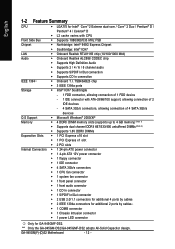
English 1-2 Feature Summary CPU Š LGA775 for GA-945GMF-DS2. GA-945GM(F)-(D)S2 Motherboard - 12 - "*" Only the GA-945GM-DS2/GA-945GMF-DS2 adopts All-Solid Capacitor design. TSB43AB23 chip Storage Š 3 IEEE 1394a ports Š Intel® ICH7 Southbrigde - 1 FDD connector, allowing connection of 4 SATA 3Gb/s devices O.S ...
English 1-2 Feature Summary CPU Š LGA775 for GA-945GMF-DS2. GA-945GM(F)-(D)S2 Motherboard - 12 - "*" Only the GA-945GM-DS2/GA-945GMF-DS2 adopts All-Solid Capacitor design. TSB43AB23 chip Storage Š 3 IEEE 1394a ports Š Intel® ICH7 Southbrigde - 1 FDD connector, allowing connection of 4 SATA 3Gb/s devices O.S ...
Manual
Page 13
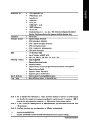
Hardware Installation For example, 4 GB of memory is reserved for GA-945GMF-DS2. "*" Only the GA-945GM-DS2/GA-945GMF-DS2 adopts All-Solid Capacitor design. - 13 - Only for system usage and therefore the actual memory size is less than the stated amount. English Rear Panel I/O &#..., a certain amount of memory size will instead be shown as 3.xx GB memory during system startup. (Note 2) To use a DDRII 667 memory module on the motherboard, you must install a 1066/800 MHz FSB processor. (Note 3) EasyTune functions may vary depending on different...
Hardware Installation For example, 4 GB of memory is reserved for GA-945GMF-DS2. "*" Only the GA-945GM-DS2/GA-945GMF-DS2 adopts All-Solid Capacitor design. - 13 - Only for system usage and therefore the actual memory size is less than the stated amount. English Rear Panel I/O &#..., a certain amount of memory size will instead be shown as 3.xx GB memory during system startup. (Note 2) To use a DDRII 667 memory module on the motherboard, you must install a 1066/800 MHz FSB processor. (Note 3) EasyTune functions may vary depending on different...
Manual
Page 14
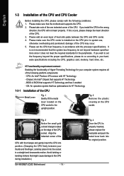
...the CPU. 3. CPU: An Intel® Pentium 4 Processor with HT Technology - Fig. 4 Once the CPU is not recommended that the motherboard supports the CPU. 2. It is properly inserted, please replace the load plate and push the metal lever back into the socket in the wrong... 1-3-1 Installation of the CPU Metal Lever Fig. 1 Gently lift the metal lever located on the CPU prior to the CPU during installation.) GA-945GM(F)-(D)S2 Motherboard - 14 - English 1-3 Installation of the CPU and CPU Cooler Before installing the CPU, please comply with the following platform components: - BIOS...
...the CPU. 3. CPU: An Intel® Pentium 4 Processor with HT Technology - Fig. 4 Once the CPU is not recommended that the motherboard supports the CPU. 2. It is properly inserted, please replace the load plate and push the metal lever back into the socket in the wrong... 1-3-1 Installation of the CPU Metal Lever Fig. 1 Gently lift the metal lever located on the CPU prior to the CPU during installation.) GA-945GM(F)-(D)S2 Motherboard - 14 - English 1-3 Installation of the CPU and CPU Cooler Before installing the CPU, please comply with the following platform components: - BIOS...
Manual
Page 15
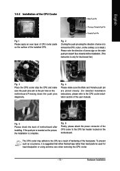
... Fig.1 Please apply an even layer of CPU cooler paste on the surface of the CPU cooler to the CPU fan header located on the motherboard. Fig. 6 Finally, please attach the power connector of the installed CPU. If the push pin is complete. The CPU cooler may adhere to the CPU... as the picture, the installation is inserted as a result of hardening of motherboard after installing. Fig. 4 Please make sure the push pins aim to the CPU cooler installation section of the user manual) Fig. 5 Please check the back...
... Fig.1 Please apply an even layer of CPU cooler paste on the surface of the CPU cooler to the CPU fan header located on the motherboard. Fig. 6 Finally, please attach the power connector of the installed CPU. If the push pin is complete. The CPU cooler may adhere to the CPU... as the picture, the installation is inserted as a result of hardening of motherboard after installing. Fig. 4 Please make sure the push pins aim to the CPU cooler installation section of the user manual) Fig. 5 Please check the back...
Manual
Page 16
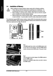
...modules have a foolproof insertion design. Insert the DIMM memory module vertically into the DIMM socket. GA-945GM(F)-(D)S2 Motherboard - 16 - The motherboard supports DDRII memory modules, whereby BIOS will automatically detect memory capacity and specifications. Reverse the installation ... Please make sure that the memory used . 2. Memory modules are unable to lock the DIMM module. It is supported by the motherboard. A memory module can differ with the following conditions: 1. English 1-4 Installation of Memory Before installing the memory modules, please comply ...
...modules have a foolproof insertion design. Insert the DIMM memory module vertically into the DIMM socket. GA-945GM(F)-(D)S2 Motherboard - 16 - The motherboard supports DDRII memory modules, whereby BIOS will automatically detect memory capacity and specifications. Reverse the installation ... Please make sure that the memory used . 2. Memory modules are unable to lock the DIMM module. It is supported by the motherboard. A memory module can differ with the following conditions: 1. English 1-4 Installation of Memory Before installing the memory modules, please comply ...
Manual
Page 18
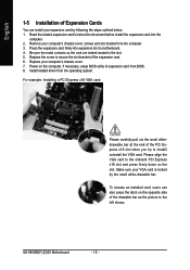
...your VGA card is locked by following the steps outlined below: 1. Be sure the metal contacts on the card are indeed seated in motherboard. 4. Replace your computer's chassis cover, screws and slot bracket from BIOS. 8. For example: Installing a PCI Express x16 VGA card:... Please carefully pull out the small whitedrawable bar at the end of the expansion card. 6. GA-945GM(F)-(D)S2 Motherboard - 18 - Remove your computer's chassis cover. 7. Press the expansion card firmly into the computer. 2. Read the related expansion card's ...
...your VGA card is locked by following the steps outlined below: 1. Be sure the metal contacts on the card are indeed seated in motherboard. 4. Replace your computer's chassis cover, screws and slot bracket from BIOS. 8. For example: Installing a PCI Express x16 VGA card:... Please carefully pull out the small whitedrawable bar at the end of the expansion card. 6. GA-945GM(F)-(D)S2 Motherboard - 18 - Remove your computer's chassis cover. 7. Press the expansion card firmly into the computer. 2. Read the related expansion card's ...
Manual
Page 20
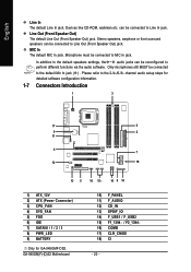
...jack. Please refer to MIC In jack. Microphone must be connected to the 2-/4-/6-/8- can be reconfigured to Line In jack. GA-945GM(F)-(D)S2 Motherboard 10) F_PANEL 11) F_AUDIO 12) CD_IN 13) SPDIF_IO 14) F_USB1 / F_USB2 15) F1_1394 / F2_1394 16) COMB ... 13 5 16 15 14 8 10 1) ATX_12V 2) ATX (Power Connector) 3) CPU_FAN 4) SYS_FAN 5) FDD 6) IDE 7) SATAII0 / 1 / 2 / 3 8) PWR_LED 9) BATTERY Only for GA-945GMF-DS2. Only microphones still MUST be connected to the default Mic In jack ( ) . Stereo speakers, earphone or front surround speakers can be connected to perform different...
...jack. Please refer to MIC In jack. Microphone must be connected to the 2-/4-/6-/8- can be reconfigured to Line In jack. GA-945GM(F)-(D)S2 Motherboard 10) F_PANEL 11) F_AUDIO 12) CD_IN 13) SPDIF_IO 14) F_USB1 / F_USB2 15) F1_1394 / F2_1394 16) COMB ... 13 5 16 15 14 8 10 1) ATX_12V 2) ATX (Power Connector) 3) CPU_FAN 4) SYS_FAN 5) FDD 6) IDE 7) SATAII0 / 1 / 2 / 3 8) PWR_LED 9) BATTERY Only for GA-945GMF-DS2. Only microphones still MUST be connected to the default Mic In jack ( ) . Stereo speakers, earphone or front surround speakers can be connected to perform different...
Manual
Page 21
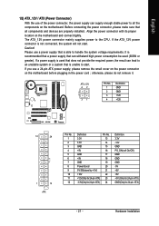
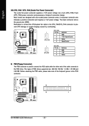
... you use a 24-pin ATX power supply, please remove the small cover on the power connector on the motherboard and connect tightly. The ATX_12V power connector mainly supplies power to all components and devices are properly installed. If a power supply is not connected, the ... +5V +5V +5V (Only for 24-pin ATX) GND(Only for 24-pin ATX) - 21 - Align the power connector with its proper location on the motherboard before plugging in the power cord ; It is unable to start . English 1/2) ATX_12V / ATX (Power Connector) With the use of the power connector, the power...
... you use a 24-pin ATX power supply, please remove the small cover on the power connector on the motherboard and connect tightly. The ATX_12V power connector mainly supplies power to all components and devices are properly installed. If a power supply is not connected, the ... +5V +5V +5V (Only for 24-pin ATX) GND(Only for 24-pin ATX) - 21 - Align the power connector with its proper location on the motherboard before plugging in the power cord ; It is unable to start . English 1/2) ATX_12V / ATX (Power Connector) With the use of the power connector, the power...
Manual
Page 22
... Sense 5) FDD (Floppy Connector) The FDD connector is the ground wire (GND). The types of the foolproof groove in the FDD connector. 33 1 34 2 GA-945GM(F)-(D)S2 Motherboard - 22 - Remember to connect the CPU/system fan cable to the CPU_FAN/SYS_FAN connector to the FDD drive. Before attaching the FDD cable, please...
... Sense 5) FDD (Floppy Connector) The FDD connector is the ground wire (GND). The types of the foolproof groove in the FDD connector. 33 1 34 2 GA-945GM(F)-(D)S2 Motherboard - 22 - Remember to connect the CPU/system fan cable to the CPU_FAN/SYS_FAN connector to the FDD drive. Before attaching the FDD cable, please...
Manual
Page 24
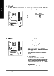
Pin No. Turn off . Re-install the battery. 4. It will blink when the system enters suspend mode(S1). Definition 1 MPD+ 2 MPD- 1 3 MPD- 9) BATTERY GA-945GM(F)-(D)S2 Motherboard Danger of used batteries according to erase CMOS... 1. Plug the power cord in the battery holder to make them short for five seconds.) 3. Dispose of ...
Pin No. Turn off . Re-install the battery. 4. It will blink when the system enters suspend mode(S1). Definition 1 MPD+ 2 MPD- 1 3 MPD- 9) BATTERY GA-945GM(F)-(D)S2 Motherboard Danger of used batteries according to erase CMOS... 1. Plug the power cord in the battery holder to make them short for five seconds.) 3. Dispose of ...
Manual
Page 26
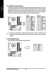
... 9 Line Out (L) 10 FSENSE2 10 NC By default, the audio driver is configured to work or even damage it. Definition 1 CD-L 1 2 GND 3 GND 4 CD-R GA-945GM(F)-(D)S2 Motherboard - 26 - Pin No. For optional front panel audio module, please contact your chassis manufacturer. Incorrect connection between the module and connector will make the...
... 9 Line Out (L) 10 FSENSE2 10 NC By default, the audio driver is configured to work or even damage it. Definition 1 CD-L 1 2 GND 3 GND 4 CD-R GA-945GM(F)-(D)S2 Motherboard - 26 - Pin No. For optional front panel audio module, please contact your chassis manufacturer. Incorrect connection between the module and connector will make the...
Manual
Page 28
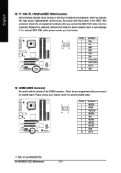
GA-945GM(F)-(D)S2 Motherboard - 28 - For optional IEEE 1394 cable, please contact your nearest dealer for optional COMB cable. 9 1 10 2 Pin No. 1 2 3 4 5 6 7 8 9 10 Definition NDCDBNSINB NSOUTB NDTRBGND NDSRBNRTSBNCTSBNRIBNo Pin Only for GA-945GMF-DS2. English 15) F1_1394 / F2_1394 (Front IEEE 1394a Connector) Serial interface standard set by Institute of the IEEE 1394 connector. Be careful with...
GA-945GM(F)-(D)S2 Motherboard - 28 - For optional IEEE 1394 cable, please contact your nearest dealer for optional COMB cable. 9 1 10 2 Pin No. 1 2 3 4 5 6 7 8 9 10 Definition NDCDBNSINB NSOUTB NDTRBGND NDSRBNRTSBNCTSBNRIBNo Pin Only for GA-945GMF-DS2. English 15) F1_1394 / F2_1394 (Front IEEE 1394a Connector) Serial interface standard set by Institute of the IEEE 1394 connector. Be careful with...
Manual
Page 30
English GA-945GM(F)-(D)S2 Motherboard - 30 -
English GA-945GM(F)-(D)S2 Motherboard - 30 -


